EP2004524B1 - Modulares band mit schwenkstäben mit einem vergrösserten haltering - Google Patents
Modulares band mit schwenkstäben mit einem vergrösserten haltering Download PDFInfo
- Publication number
- EP2004524B1 EP2004524B1 EP07710826.4A EP07710826A EP2004524B1 EP 2004524 B1 EP2004524 B1 EP 2004524B1 EP 07710826 A EP07710826 A EP 07710826A EP 2004524 B1 EP2004524 B1 EP 2004524B1
- Authority
- EP
- European Patent Office
- Prior art keywords
- opening
- belt
- pivot rod
- link
- link end
- Prior art date
- Legal status (The legal status is an assumption and is not a legal conclusion. Google has not performed a legal analysis and makes no representation as to the accuracy of the status listed.)
- Not-in-force
Links
Images


Classifications
-
- B—PERFORMING OPERATIONS; TRANSPORTING
- B65—CONVEYING; PACKING; STORING; HANDLING THIN OR FILAMENTARY MATERIAL
- B65G—TRANSPORT OR STORAGE DEVICES, e.g. CONVEYORS FOR LOADING OR TIPPING, SHOP CONVEYOR SYSTEMS OR PNEUMATIC TUBE CONVEYORS
- B65G17/00—Conveyors having an endless traction element, e.g. a chain, transmitting movement to a continuous or substantially-continuous load-carrying surface or to a series of individual load-carriers; Endless-chain conveyors in which the chains form the load-carrying surface
- B65G17/06—Conveyors having an endless traction element, e.g. a chain, transmitting movement to a continuous or substantially-continuous load-carrying surface or to a series of individual load-carriers; Endless-chain conveyors in which the chains form the load-carrying surface having a load-carrying surface formed by a series of interconnected, e.g. longitudinal, links, plates, or platforms
- B65G17/08—Conveyors having an endless traction element, e.g. a chain, transmitting movement to a continuous or substantially-continuous load-carrying surface or to a series of individual load-carriers; Endless-chain conveyors in which the chains form the load-carrying surface having a load-carrying surface formed by a series of interconnected, e.g. longitudinal, links, plates, or platforms the surface being formed by the traction element
- B65G17/086—Conveyors having an endless traction element, e.g. a chain, transmitting movement to a continuous or substantially-continuous load-carrying surface or to a series of individual load-carriers; Endless-chain conveyors in which the chains form the load-carrying surface having a load-carrying surface formed by a series of interconnected, e.g. longitudinal, links, plates, or platforms the surface being formed by the traction element specially adapted to follow a curved path
-
- B—PERFORMING OPERATIONS; TRANSPORTING
- B65—CONVEYING; PACKING; STORING; HANDLING THIN OR FILAMENTARY MATERIAL
- B65G—TRANSPORT OR STORAGE DEVICES, e.g. CONVEYORS FOR LOADING OR TIPPING, SHOP CONVEYOR SYSTEMS OR PNEUMATIC TUBE CONVEYORS
- B65G17/00—Conveyors having an endless traction element, e.g. a chain, transmitting movement to a continuous or substantially-continuous load-carrying surface or to a series of individual load-carriers; Endless-chain conveyors in which the chains form the load-carrying surface
- B65G17/30—Details; Auxiliary devices
- B65G17/38—Chains or like traction elements; Connections between traction elements and load-carriers
- B65G17/40—Chains acting as load-carriers
-
- B—PERFORMING OPERATIONS; TRANSPORTING
- B65—CONVEYING; PACKING; STORING; HANDLING THIN OR FILAMENTARY MATERIAL
- B65G—TRANSPORT OR STORAGE DEVICES, e.g. CONVEYORS FOR LOADING OR TIPPING, SHOP CONVEYOR SYSTEMS OR PNEUMATIC TUBE CONVEYORS
- B65G21/00—Supporting or protective framework or housings for endless load-carriers or traction elements of belt or chain conveyors
- B65G21/16—Supporting or protective framework or housings for endless load-carriers or traction elements of belt or chain conveyors for conveyors having endless load-carriers movable in curved paths
- B65G21/18—Supporting or protective framework or housings for endless load-carriers or traction elements of belt or chain conveyors for conveyors having endless load-carriers movable in curved paths in three-dimensionally curved paths
-
- B—PERFORMING OPERATIONS; TRANSPORTING
- B65—CONVEYING; PACKING; STORING; HANDLING THIN OR FILAMENTARY MATERIAL
- B65G—TRANSPORT OR STORAGE DEVICES, e.g. CONVEYORS FOR LOADING OR TIPPING, SHOP CONVEYOR SYSTEMS OR PNEUMATIC TUBE CONVEYORS
- B65G2207/00—Indexing codes relating to constructional details, configuration and additional features of a handling device, e.g. Conveyors
- B65G2207/12—Chain pin retainers
Definitions
- the present invention relates to a modular belt and a method of removing a rod retaining snap rod from a modular belt.
- Modular plastic conveyor belts are made up of molded plastic modular links, or belt modules, that can be arranged side by side in rows of selectable width.
- a series of spaced apart link ends extending from each side of the modules include aligned apertures to accommodate a pivot rod.
- the link ends along one end of a row of modules are interconnected with link ends of an adjacent row.
- a pivot rod journaled in the aligned apertures of the side-by-side and end-to-end connected modules forms a hinge between adjacent rows. Rows of belt modules are then connected together to form an endless conveyor belt capable of articulating about a drive sprocket.
- the retention of the pivot rod is an important feature of the modular plastic conveyor belts. Rod retention can be accomplished by enlarging the heads of the pivot rods at both ends but such would not allow for disassembly without destroying the rod head. Headless rods have been used for easier production and belt assembly. These types of rods must be blocked at both ends of the belt during use. In addition headless rods are often difficult to remove for disassembly.
- One approach to rod retention is to have a head at one end of a rod and a headless section at the opposite end.
- the headed rod is furnished with a rod retaining ring disposed on the shaft at a distance from the head portion of the rod.
- the rod is inserted through the pivot holes of the module links, which are all exactly the same diameter.
- the retaining ring is just a little bit larger in diameter than the pivot hole of the outermost link, such that the ring may be forced through the pivot hole of the outermost link end and is able to expand behind the link.
- the rod is kept firmly in position by the retaining ring.
- the system described above has the drawback that it requires tight tolerances of the hole diameter of the outermost link and the retaining ring diameter. In practice, there is a risk that the rod does not retain well enough or is retained tightly and cannot be easily disassembled. In addition, if the retaining ring is a little too large, it may be sheared off when inserted.
- EP 1 500 614 A1 discloses a modulator belt according to the preamble of claim 1 and claim 10, the modular belt having headed pivot rods furnished with a rod retaining ring disposed on the shaft at a distance from the head portion of the rod.
- the rod is inserted through the pivot holes of the module links.
- the pivot hole of an outermost link end is larger than the other pivot holes and offset in the direction of belt travel from a central longitudinal axis of the other pivot holes such that the retaining ring may be pushed through the pivot hole of the outermost link end when the pivot rod is bent.
- a screw driver is inserted under the head of the pivot rod to provide leverage for bending the rod. This method is not applicable to pivot rods without head.
- the present invention meets the above-described need by providing modular belts and a method of removing a rod retaining snap rod from a modular belt according to independent claims 1, 7 and 10. Preferred embodiments are defined in the dependent claims.
- the present invention meets the above-described need by providing a snap rod system such that the retaining ring can be made larger in order to increase the size of the shoulder which engages behind the link face.
- the bore of the outermost link needs to be enlarged accordingly in order to allow the larger retaining ring to be moved through the bore. Due to the larger difference between the retaining ring and the rod diameter, the tolerance becomes less critical.
- the bore of the outermost link end is slightly eccentric in such a way that the enlarged shoulder of the retaining ring will be clearly overlapping the link face when assembled. When the belt is under tension the rod will be firmly forced into this retaining position, without losing the ability to transmit the belt pull.
- a modular belt 10 being not part of the present invention is formed from a plurality of belt modules as will be evident to those of ordinary skill in the art.
- the outermost modules 13, 16 are shown.
- the belt 10 may be formed into varying widths in bricklayed fashion in a direction perpendicular to the direction of belt travel 34.
- Each module 13, 16 has a module body 20 with a first and second plurality of link ends 22, 25 disposed in the middle of the module with respect to the outer edge 12 shown at the top of Figure 1 .
- Each link end 22, 25 has opposed side walls 23, 24 defining a first transverse thickness 21.
- the first transverse thickness 21 is connected to the intermediate section 26 of the module body 20 at a first proximal portion 27.
- the transverse thickness extends from the intermediate section 26 in a direction of belt travel to a first distal portion 29.
- the link ends 22, 25 include openings 28, 31 disposed transverse to the direction of belt travel 34.
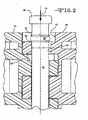
- the openings 28 and 31 receive the pivot rod 19 when adjacent belt modules 13, 16 are intercalated as shown in the figure.
- the pivot rod 19 is typically round and has a diameter 30 such that the modules 13, 16 are capable of pivoting relative to each other for articulating about a sprocket (not shown).
- the pivot rod 19 has an end portion 46 with a diameter 47 that is greater than the diameter 30 of the pivot rod 19.
- the pivot rod 19 also includes a retaining ring 60 spaced apart longitudinally from the end portion 46.
- the retaining ring 60 has a diameter D R that is larger than the diameter of the pivot rod 19 and may be formed with a chamfered or beveled edge 63.
- Outermost link end 40 of module 16 is disposed toward the edge 12 of belt 10.
- the outermost link end 40 has a recessed portion 43 that is capable of receiving end portion 46 of pivot rod 19.
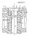
- the pivot rod 19 is installed in the belt 10 in the direction indicated by arrow 49, the end portion 46 is received in the recessed portion 43 and abuts with the portion of the link end surrounding aperture 52 as shown in Fig. 4 .
- Link end 40 has an opening 52 with a diameter D 1 that is approximately equal to or slightly smaller than the diameter D R of the ring 60 but is larger than the diameter D 2 of openings 28, 31.
- Belt module 13 also has a specially formed outermost link end 55 having a recessed surface 56.
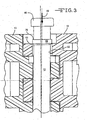
- the central longitudinal axis 65 of aperture 52 is offset from the central longitudinal axis 67 of openings 28, 31 such that upon insertion, the pivot rod 19 is bent as shown in Fig. 3 .
- the pivot rod 19 is bent during insertion such that once the ring 60 clears aperture 52, the enlarged shoulder 75 overlaps the link face surrounding aperture 52 as shown in the circled area 76 in Fig. 4 .
- the axial misalignment between the apertures 52 and 31 ensures that the ring 60 does not exit from the aligned modules 13 and 16 after installation.
- Figs. 2-4 illustrate the position of the pivot rod 19 and the modules 13 and 16 during various stages of the installation of the pivot rod 19.
- the pivot rod 19 is shown at the maximum insertion point prior to bending the body or shaft of the pivot rod 19.
- the rod 19 has been inserted in the direction of arrow 49 until the beveled edge 63 of the retaining ring 60 engages with the edge of the opening 52 on the left hand side of the figure.
- retaining ring 60 aligns with the opening 52.
- the retaining ring 60 is sized to frictionally engage with the inside walls of opening 52 during insertion. Accordingly, the retaining ring may be roughly equal to or slightly larger in diameter D R than the inside diameter D 1 of opening 52. As shown, the left hand side of the beveled edge 63 clears the opening in Fig. 3 so that the retaining ring 60 may be passed through the opening 52.
- Fig. 5 an alternate embodiment of the prior art is shown.
- the overlapping area 100 located between the outermost link end 103 on the first belt module 104 and the rod retaining ring 106 defines the locking behavior of the snap rod.
- the offset 107 between the pivot rod center axis 109 and the central axis 111 of opening 112 in the outermost link end 103 for the retaining ring 106 is a parameter that affects the locking behavior.
- This offset 107 can be increased by reducing the diameter D 4 of the rod 118 between the head 121 and the retaining ring 106.
- This arrangement allows the diameter of the retaining ring 106 to be kept slightly less than or equal to the diameter of opening 112 and thus makes removal of the pivot rod easier without weakening the retaining function.
- the outermost link end 103 has a recessed portion 122 that receives the head 121.
- the opening 112 in the outermost link end 103 is larger than the openings 127 in the plurality of link ends 130.
- the diameter D 3 of the rod 118 in the region of the openings 127 is larger than the diameter D 4 of the rod 118 between the head 121 and the retaining ring 106.
- the second belt module 133 also has an outermost link end 136 having a recessed portion 139.
- the recessed portion 139 in the second belt module 133 receives the retaining ring 106 when the first and second belt modules 104, 133 are intercalated and connected by the pivot rod 118.
- the outermost link end 136 on the second belt module 133 has a pivot rod opening 140 with a diameter 143 that is approximately equal to the diameter of the openings 127 in the first belt module 104.
- the offset 107 is shown from an end view of the intercalated belt modules.
- the pivot rod axis 109 and the central axis 111 of the opening 112 are shown.
- the pivot rod 118 may be removed by use of a screw driver 200.
- the screw driver 200 may be inserted under the head 121 of the pivot rod 118 to provide leverage for bending the rod 118 to align it with the opening 112 in the outermost link end 103 in the first module 104. Once the retaining ring 106 is aligned with the opening 112 the pivot rod 118 may be removed by sliding it outward in the direction indicated by arrow 203.
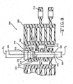
- a belt 300 is formed from modules 303 and 306.
- the modules have outer link ends 309, 312.
- Link end 309 on module 306 has extra width to accommodate an internal opening 315 for receiving retaining ring 360 on pivot rod 319.
- Link end 312 on module 303 intercalates adjacent to link end 309 as shown.
- the link end 309 also includes a recessed portion 318 for receiving end portion 346 of pivot rod 319.
- Link end 309 also includes an opening 321 having the same diameter as opening 315. Openings 315 and 321 have a diameter D 1 that is approximately equal to or smaller than the diameter D r of ring 360 which is formed with a chamfered or beveled edge 363. The link end 312 and the link ends disposed toward the middle of the belt have openings with a Diameter D 2 that is smaller than D 1 . The longitudinal axis 325 of openings 315 and 321 is offset from the longitudinal axis 330 of the opening in link end 312 and the openings toward the middle of the belt module.
- the pivot rod 319 has to be bent and once the ring 360 clears the opening 315 it shifts to the left with respect to Fig. 8 such that shoulder 375 engages the link surface around opening 315.
- Fig. 8 may also be provided with a pivot rod 118 ( Fig. 5 ) having different diameters located above and below the retaining ring 106.
- the diameter of the rod between the retaining ring and the head is smaller than the diameter of the rod between the retaining ring and the second end of the rod.
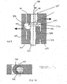
- FIG. 9-12 an embodiment of the invention is shown.
- a portion of a modular belt 400 is shown in cross-section.
- a first module 403 has a plurality of link ends 406 having an opening 409 disposed therethrough.
- the outermost link end 412 on module 403 has an opening 415 disposed therethrough.
- the opening 415 is wider than the remaining openings 409.
- the opening 415 has a central axis 418 that is offset from a central axis 421 of openings 409.
- the wider opening and offset axis provide for rod retention by means of a pivot rod 424 having an enlarged retaining ring 427.
- Retaining ring 427 has an outside diameter that is greater than the outside diameter of the pivot rod 424.
- a second module 430 has a plurality of link ends 433 that have openings 438 that are capable of aligning with openings 409. Link ends 433 fit into spaces disposed between link ends 406.
- the outermost link end 436 on the second module 430 has a first recess 439 for receiving the enlarged retaining ring 427 when modules 403, 430 are intercalated and connected by pivot rod 424 to form the belt 400.
- the outermost link end 436 on the second module 430 also has a second recess 440.
- the second recess 440 is sized to receive the head of a screwdriver or the like.
- the rod 424 When the pivot rod 424 is inserted into the intercalated modules 403, 430 to form a belt 400, the rod 424 is initially deformed as shown in Fig. 3 . Once the retaining ring 427 clears the opening 415, the pivot rod 424 moves to the left of the figure (best shown in Figs. 4 and 9 ) and a shoulder 442 formed by the ring 427 and rod 424 abuts with the side surface of link end 412 such that the pivot rod 424 is fixed between the outermost link ends 412, 436 on the first and second belt modules 403, 430 respectively.
- the edge of the outermost link end 412 is solid except for the opening 415.
- the pivot rod 424 does not have a head at the end.
- the ring 427 is disposed in spaced apart relation to the end of the pivot rod 424. Accordingly, the pivot rod 424 cannot be removed from the edge of the belt 400 in the manner shown in Fig. 7 .
- a screwdriver blade 441 or the like can be inserted into the second recess 440 in order to engage with ring 427 to remove the pivot rod 424 in the direction of arrow 445.
- a standard screw driver 480 with a flat head can be inserted downward from the top of the belt 400 or alternatively upwards from the bottom of the belt 400, in order to remove the pivot rod 424 for disassembling the modules for repair or maintenance.
- a belt module 500 is shown with a pivot rod 503 retained in a double width outermost link end 506.
- the link end 506 has a first transverse opening 509 which has a diameter that is slightly larger than the diameter of the pivot rod 503.
- the pivot rod 503 has a retaining ring 512 that has a diameter that is greater than the diameter of the pivot rod 503.
- the pivot rod 503 also has a head portion 515 located at the outermost end of the pivot rod 503.
- the retaining ring 512 is disposed in spaced apart relation to the head portion 515.
- the link end 506 has a second transverse opening 518 that is offset to the right with respect to the orientation of Fig. 13 .
- the transverse opening 518 is larger than transverse opening 509.
- pivot rod 503 can be elastically deformed as shown on the right hand side of Fig. 13 to enable the pivot rod 503 to exit from the belt to release the module 500.
- a link end 521 extends opposite from link end 506 and is capable of intercalating with an adjacent module 500.
- the outermost transverse opening 518 has an oblong shape that partially overlaps the transverse opening 509.
- a curved wall 519 of opening 518 substantially coincides with a curved wall 520 of opening 509.
- the curved wall 519 of opening 518 coincides with the curved wall 520 of opening 509 until a point 510 on both sides of opening 518 toward the middle of the pivot rod 503 where curved wall 519 terminates and a larger diameter curved wall 525 emerges.
- the combination of the curved wall 519 and the curved wall 525 forms an oblong shaped opening that partially coincides with the transverse opening 509.
- the retaining ring 512 overlaps more of the link face 527 ( Fig. 13 ) around opening 518 thereby improving the rod retaining function of the arrangement.
- Figs. 15-16 adjacent modules 500 are shown connected by a headless pivot rod 550.
- the module 500 may extend to the belt edge around opening 553.
- the rod 550 may be removed by inserting a tool or implement into the space inside the outermost double link to pry the rod 550 out by means of engagement with the retaining ring 558.
- the retaining ring 558 has a larger diameter than pivot rod 550, and the ring 558 provides a leverage point for removing the pivot rod 550 as shown on the right hand side of Fig. 15 .
- the outermost transverse opening 518 has an oblong shape with a first curved wall 519 and a second curved wall 525 as described above.
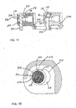
- belt module 600 is shown with a pivot rod 603 retained in a double width outermost link end 606.
- the link end 606 has a first transverse opening 609 which has a diameter that is slightly larger than the diameter of the pivot rod 603.
- the pivot rod 603 has a retaining ring 612 that has a diameter that is greater than the diameter of the pivot rod 603.
- the pivot rod 603 also has a head portion 615 located at the outermost end of the pivot rod 603.
- the retaining ring 612 is disposed in spaced apart relation to the head portion 615.
- the link end 606 has a second transverse opening 618 that is offset to the right with respect to the orientation of Fig. 17 .
- the transverse opening 618 is larger than transverse opening 609.
- pivot rod 603 can be elastically deformed as shown on the right hand side of Fig. 17 to enable the pivot rod 603 to exit from the belt to release the module 600.
- a link end 621 extends opposite from link end 606 and is capable of intercalating with an adjacent module 600.
- the outermost transverse opening 618 has a generally oblong shape that partially overlaps the transverse opening 609.
- a curved wall 619 of opening 618 substantially coincides with a curved wall 620 of opening 609.
- the curved wall 619 of opening 618 coincides with the curved wall 620 of opening 609 until a point toward the middle of the pivot rod 603 where the curved portion terminates and a substantially tangential wall 622 extends on both sides of opening 618 to a larger diameter curved wall 625.
- the combination of the curved wall 619, tangential wall 622, and the curved wall 625 forms an oblong-shaped opening 618 that partially coincides with the transverse opening 609.
- the retaining ring 612 overlaps more of the link face 639 ( Fig. 17 ) around opening 618 thereby improving the rod retaining function of the arrangement.
- a headless pivot rod 650 adjacent modules 600 are shown connected by a headless pivot rod 650.
- the module 600 may extend to the belt edge around opening 653.
- the rod 650 may be removed by inserting a tool or implement into the space inside the outermost double link to pry the rod 650 out by means of engagement with the retaining ring 658.
- the retaining ring 658 has a larger diameter than pivot rod 650, and the ring 658 provides a leverage point for removing the pivot rod 650 as shown on the right hand side of Fig. 19 .
- the outermost transverse opening 618 has an oblong shape with a first curved wall 619 and a second curved wall 625 connected by a substantially tangential wall 622 as described above.
- a module 700 being not part of the present invention and having an outermost link end 703 with a single link configuration is shown.
- the outermost link end 700 has a transverse opening 706 that is larger than the remaining transverse openings 709. Also, transverse opening 706 is offset to the right with respect to the figure such that the pivot rod 712 can be elastically deformed for removal through opening 706 as shown in connection with the pivot rod 712 on the right hand side of the figure.
- the pivot rod 712 has a retaining ring 715 that has an outside diameter that is larger than the diameter of the pivot rod 712.
- the adjacent module 700 may be provided with a recessed portion 728 to provide space for the retaining ring 715 when the adjacent modules 700 are intercalated and connected by a pivot rod 712.
- an alternative embodiment being not part of the present invention provides a module 744 having a recess 750 in the outermost link end 755 that faces the link end 760 on the adjacent module 744.
- the retaining ring 715 is disposed in the recess 750 formed in module 744.
Landscapes
- Engineering & Computer Science (AREA)
- Mechanical Engineering (AREA)
- Chain Conveyers (AREA)
- Buckles (AREA)
- Clamps And Clips (AREA)
- Mutual Connection Of Rods And Tubes (AREA)
Claims (14)
- Modulband (400), umfassend:eine Mehrzahl von Bandmodulen (403, 430) mit einer ersten Mehrzahl von Verbindungsenden (406), wobei jedes Verbindungsende (406) gegenüberliegende Seitenwände aufweist, die eine erste Querdicke bereitstellen, verbunden mit einem Zwischenteil an einem ersten proximalen Bereich und sich vom Zwischenteil in einer Bandlaufrichtung zu einem ersten distalen Bereich an den Verbindungsenden (406) erstreckend, wobei die erste Mehrzahl von Verbindungsenden (406) erste Öffnungen (409) durch die erste Querdicke zwischen und zu den gegenüberliegenden Seitenwänden aufweist, die Module (403, 430) ein erstes äusserstes Verbindungsende (412) aufweisen, das erste äusserste Verbindungsende (412) zur ersten Mehrzahl von Verbindungsenden (406) benachbart ist und gegenüberliegende Seitenwände aufweist, die eine zweite Querdicke bereitstellen, verbunden mit dem Zwischenteil an einem zweiten proximalen Bereich und sich vom Zwischenteil in einer Bandlaufrichtung zu einem zweiten distalen Bereich am Verbindungsende (412) erstreckend, wobei das erste äusserste Verbindungsende (412) eine zweite Öffnung (415) durch die zweite Querdicke zwischen und zu den gegenüberliegenden Seitenwänden aufweist, die zweite Öffnung (415) grösser als die ersten Öffnungen (409) ist, die zweite Öffnung (415) in Bandlaufrichtung zu einer Längsmittelachse (421) der ersten Öffnungen (409) versetzt ist, wobei die Module (403, 430) eine zweite Mehrzahl von Verbindungsenden (433) aufweisen, jedes Verbindungsende (433) gegenüberliegende Seitenwände aufweist, die eine dritte Querdicke bereitstellen, verbunden mit einem Zwischenteil an einem dritten proximalen Bereich und sich vom Zwischenteil in einer Bandlaufrichtung entgegengesetzt zur Erstreckungsrichtung der ersten Mehrzahl von Verbindungsenden (406) zu einem dritten distalen Bereich an den Verbindungsenden (433) erstreckend, wobei die zweite Mehrzahl von Verbindungsenden (433) dritte Öffnungen durch die dritte Querdicke zwischen und zu den gegenüberliegenden Seitenwänden aufweist, die Module (403, 430) ein zweites äusserstes Verbindungsende (436) aufweisen, das zweite äusserste Verbindungsende (436) benachbart zur zweiten Mehrzahl von Verbindungsenden (433) ist und gegenüberliegende Seitenwände aufweist, die eine vierte Querdicke bereitstellen, verbunden mit dem Zwischenteil an einem vierten proximalen Bereich und sich vom Zwischenteil in einer Bandlaufrichtung zu einem vierten distalen Bereich am Verbindungsende (436) erstreckend, wobei das zweite äusserste Verbindungsende (436) eine vierte Öffnung (438) durch die vierte Querdicke zwischen und zu den gegenüberliegenden Seitenwänden aufweist; undDrehstäbe (424), wobei jeder Drehstab (424) einen länglichen Körper mit einem ersten Durchmesser aufweist, der Drehstab (424) ein gegenüber einem zweiten Ende angeordnetes erstes Ende aufweist, der Drehstab (424) eine quer zur Bandlaufrichtung angeordnete Längsachse aufweist, der Drehstab (424) einen Haltering (427) aufweist, der in der Richtung der Längsachse zum ersten Ende des Drehstabs (424) beabstandet angeordnet ist, jeder Drehstab (424) durch die ersten Öffnungen (409) und die zweite Öffnung (415) eines Bandmoduls (403) und die dritten Öffnungen (438) und die vierte Öffnung (438) des benachbarten Moduls (430) angeordnet ist,
und wobei das zweite äusserste Verbindungsende (436) eine erste Aussparung (439) zum Aufnehmen des Halterings (427) des Drehstabs (424) aufweist,dadurch gekennzeichnet, dass das zweite äusserste Verbindungsende (436) eine zweite Aussparung (440) aufweist, welche gekrümmt und darin ausgebildet ist, um ein Werkzeug (441, 480) zum Eingreifen in den Drehstab (424) zu dessen Entfernung aufzunehmen. - Modulband (400) nach Anspruch 1, wobei die zweite Aussparung (440) zum Aufnehmen eines Werkzeugs (441, 480) zur Entfernung des Drehstabs (424) halbkreisförmig ist.
- Modulband (400) nach Anspruch 1 oder 2, wobei die zweite Aussparung (440) zum Aufnehmen eines Werkzeugs (441, 480) zur Entfernung des Drehstabs (424) durch eine gekrümmte Wand (451) zur Drehung einer Schraubendreherklinge (441) begrenzt ist.
- Modulband (400) nach einem der Ansprüche 1 bis 3, wobei die zweite Aussparung (440) zum Aufnehmen eines Werkzeugs (441, 480) zur Entfernung des Drehstabs (424) in einem Abschnitt des zweiten äussersten Verbindungsendes (436) und einem Abschnitt des Zwischenteils ausgebildet ist.
- Modulband (400) nach einem der Ansprüche 1 bis 4, wobei sich das erste äusserste Verbindungsende (412) um die zweite Öffnung (415) im ersten äussersten Verbindungsende (412) zur Kante des Bandes (400) erstreckt.
- Modulband (400) nach einem der Ansprüche 1 bis 5, wobei der Drehstab (424) keinen Kopf aufweist.
- Verfahren zum Entfernen eines Stabrückhalte-Schnappstabs (424) aus einem Modulband (400), wobei das Verfahren umfasst:Bereitstellen einer Mehrzahl von Bandmodulen (403, 430) mit einer ersten Mehrzahl von Verbindungsenden (406), wobei jedes Verbindungsende (406) gegenüberliegende Seitenwände aufweist, die eine erste Querdicke bereitstellen, verbunden mit einem Zwischenteil an einem ersten proximalen Bereich und sich vom Zwischenteil in einer Bandlaufrichtung zu einem ersten distalen Bereich an den Verbindungsenden (406) erstreckend, wobei die erste Mehrzahl von Verbindungsenden (406) erste Öffnungen (409) durch die erste Querdicke zwischen und zu den gegenüberliegenden Seitenwänden aufweist, die Module (403, 430) ein erstes äusserstes Verbindungsende (412) aufweisen, das erste äusserste Verbindungsende (412) zur ersten Mehrzahl von Verbindungsenden (406) benachbart ist und gegenüberliegende Seitenwände aufweist, die eine zweite Querdicke bereitstellen, verbunden mit dem Zwischenteil an einem zweiten proximalen Bereich und sich vom Zwischenteil in einer Bandlaufrichtung zu einem zweiten distalen Bereich am Verbindungsende (412) erstreckend, wobei das erste äusserste Verbindungsende (412) eine zweite Öffnung (415) durch die zweite Querdicke zwischen und zu den gegenüberliegenden Seitenwänden aufweist, die zweite Öffnung (415) grösser als die ersten Öffnungen (409) ist, die zweite Öffnung (415) in Bandlaufrichtung von einer Längsmittelachse (421) der ersten Öffnungen (409) versetzt ist, wobei die Module (403, 430) eine zweite Mehrzahl von Verbindungsenden (433) aufweisen, jedes Verbindungsende (433) gegenüberliegende Seitenwände aufweist, die eine dritte Querdicke bereitstellen, verbunden mit einem Zwischenteil an einem dritten proximalen Bereich und sich vom Zwischenteil in einer Bandlaufrichtung entgegengesetzt zur Erstreckungsrichtung der ersten Mehrzahl von Verbindungsenden (406) zu einem dritten distalen Bereich an den Verbindungsenden (433) erstreckend, wobei die zweite Mehrzahl von Verbindungsenden (433) dritte Öffnungen durch die dritte Querdicke zwischen und zu den gegenüberliegenden Seitenwänden aufweist, die Module (403, 430) ein zweites äusserstes Verbindungsende (436) aufweisen, das zweite äusserste Verbindungsende (436) benachbart zur zweiten Mehrzahl von Verbindungsenden (433) ist und gegenüberliegende Seitenwände aufweist, die eine vierte Querdicke bereitstellen, verbunden mit dem Zwischenteil an einem vierten proximalen Bereich und sich vom Zwischenteil in einer Bandlaufrichtung zu einem vierten distalen Bereich am Verbindungsende (436) erstreckend, wobei das zweite äusserste Verbindungsende (436) eine vierte Öffnung (438) durch die vierte Querdicke zwischen und zu den gegenüberliegenden Seitenwänden, eine erste Aussparung (439) zum Aufnehmen eines Halterings (427) eines Drehstabs (424) und eine zweite Aussparung (440) aufweist, welche gekrümmt und darin ausgebildet ist, um ein Werkzeug (441, 480) aufzunehmen; undBereitstellen von Drehstäben (424), wobei jeder Drehstab (424) einen länglichen Körper mit einem ersten Durchmesser aufweist, der Drehstab (424) ein gegenüber einem zweiten Ende angeordnetes erstes Ende aufweist, der Drehstab (424) eine quer zur Bandlaufrichtung angeordnete Längsachse aufweist, der Drehstab (424) einen Haltering (427) aufweist, der in der Richtung der Längsachse zum ersten Ende des Drehstabs (424) beabstandet angeordnet ist, jeder Drehstab (424) durch die ersten Öffnungen (409) und die zweite Öffnung (415) eines Bandmoduls (403) und die dritten Öffnungen (438) und die vierte Öffnung (438) des benachbarten Moduls (430) angeordnet ist, derart dass der Haltering (427) in der ersten Aussparung (439) aufgenommen und zwischen dem ersten äussersten Verbindungsende (412) eines der Module (403, 430) und dem zweiten äussersten Verbindungsende (436) des benachbarten Moduls (403, 430) angeordnet wird, wenn die Module (403, 430) zusammengefügt werden;Einführen eines Werkzeugs (441, 480) in die zweite Aussparung (440) des zweiten äussersten Verbindungsendes (436); undDas Werkzeug (441, 480) mit dem Haltering (427) in Eingriff bringen, um den Drehstab (424) zur Entfernung durch die erste Öffnung (409) im ersten äussersten Verbindungsende (412) elastisch zu verformen.
- Verfahren nach Anspruch 7, wobei das Werkzeug eine Schraubendreherklinge (441) ist.
- Verfahren nach Anspruch 7 oder 8, wobei die zweite Aussparung (440) zum Aufnehmen eines Werkzeugs (441, 480) zur Entfernung des Drehstabs (424) im Wesentlichen halbkreisförmig ausgebildet ist.
- Modulband, umfassend:eine Mehrzahl von Bandmodulen (500; 600) mit einer ersten Mehrzahl von Verbindungsenden, wobei jedes Verbindungsende gegenüberliegende Seitenwände aufweist, die eine erste Querdicke bereitstellen, verbunden mit einem Zwischenteil an einem ersten proximalen Bereich und sich vom Zwischenteil in einer Bandlaufrichtung zu einem ersten distalen Bereich an den Verbindungsenden erstreckend, wobei die erste Mehrzahl von Verbindungsenden erste Öffnungen durch die erste Querdicke zwischen und zu den gegenüberliegenden Seitenwänden aufweist, die Module (500; 600) ein äusserstes Verbindungsende (506; 606) aufweisen, das äusserste Verbindungsende (506; 606) zur ersten Mehrzahl von Verbindungsenden benachbart ist und gegenüberliegende Seitenwände aufweist, die eine zweite Querdicke bereitstellen, verbunden mit dem Zwischenteil an einem zweiten proximalen Bereich und sich vom Zwischenteil in einer Bandlaufrichtung zu einem zweiten distalen Bereich am Verbindungsende (506; 606) erstreckend, wobei das äusserste Verbindungsende (506; 606) eine zweite Öffnung (518; 618) durch die zweite Querdicke zwischen und zu den gegenüberliegenden Seitenwänden aufweist, die zweite Öffnung durch eine gekrümmte Wand begrenzt ist, die zweite Öffnung (518; 618) einen ersten Abschnitt aufweist, der durch eine kreisförmige Wand (519; 619) begrenzt ist, die durch einen ersten Durchmesser definiert ist, und einen zweiten Abschnitt aufweist, der durch eine kreisförmige Wand (525; 625) begrenzt ist, die durch einen zweiten Durchmesser definiert ist, wobei die Bandmodule (500; 600) eine zweite Mehrzahl von Verbindungsenden (521; 621) aufweisen, die sich vom Zwischenteil in einer Bandlaufrichtung entgegengesetzt zur Erstreckungsrichtung der ersten Mehrzahl von Verbindungsenden erstrecken und darin definierte dritte Queröffnungen aufweisen; undDrehstäbe (503; 550; 603; 650), wobei jeder Drehstab (503; 550; 603; 650) einen länglichen Körper mit einem dritten Durchmesser, ein gegenüber von einem zweiten Ende angeordnetes erstes Ende, eine quer zur Bandlaufrichtung angeordnete Längsachse und einen Haltering (512; 558; 612; 658) aufweist, der in der Richtung der Längsachse zum ersten Ende des Drehstabs (503; 550; 603; 650) beabstandet angeordnet ist, wobei jeder Drehstab (503; 550; 603; 650), um das Band zu bilden, durch die ersten Öffnungen und die zweite Öffnung (518; 618) eines Bandmoduls (500; 600) und die dritten Öffnungen des benachbarten Moduls (500; 600) angeordnet ist, und wobei das äusserste Verbindungsende (506; 606) eine erste Aussparung zum Aufnehmen des Halterings (512; 558; 612; 658) des Drehstabs (503; 550; 603; 650) aufweist,dadurch gekennzeichnet, dass der erste Durchmesser der kreisförmigen Wand (519; 619) des ersten Abschnitts der zweiten Öffnung (518; 618) ungefähr gleich dem Durchmesser der ersten Öffnungen ist, der zweite Durchmesser der kreisförmigen Wand (525; 625) des zweiten Abschnitts der zweiten Öffnung (518; 618) grösser als der erste Durchmesser der kreisförmigen Wand (519; 619) des ersten Abschnitts der zweiten Öffnung (518; 618) ist, und der Haltering (512; 558; 612; 658) des Drehstabs (503; 550; 603; 650) einen Durchmesser aufweist, der kleiner als der zweite Durchmesser der zweiten Öffnung (518; 618), jedoch grösser als der erste Durchmesser der zweiten Öffnung (518; 618) ist.
- Modulband nach Anspruch 10, wobei die gekrümmte Wand der zweiten Öffnung (518) mit der kreisförmigen Wand (519) des ersten Abschnitts bis zu einem Punkt (510) auf beiden Seiten der zweiten Öffnung (518) zusammentrifft, und wobei die gekrümmte Wand der zweiten Öffnung (518) auf der anderen Seite der zwei Punkte (510) mit der kreisförmigen Wand (525) des zweiten Abschnitts zusammentrifft.
- Modulband nach Anspruch 10, wobei die kreisförmige Wand (619) des ersten Abschnitts und die kreisförmige Wand (625) des zweiten Abschnitts auf beiden Seiten der zweiten Öffnung (618) durch eine Tangentialwand (622) verbunden sind.
- Modulband nach einem der Ansprüche 10 bis 12, wobei das äusserste Verbindungsende (506; 606) die Dicke eines einzelnen Verbindungsendes der ersten Mehrzahl von Verbindungsenden aufweist.
- Modulband nach einem der Ansprüche 10 bis 12, wobei das äusserste Verbindungsende (506; 606) die Dicke von zwei Verbindungsenden der ersten Mehrzahl von Verbindungsenden aufweist.
Applications Claiming Priority (2)
| Application Number | Priority Date | Filing Date | Title |
|---|---|---|---|
| US11/278,602 US7331447B2 (en) | 2003-07-24 | 2006-04-04 | Rod retaining snap rod with enlarged retaining ring |
| PCT/CH2007/000168 WO2007112610A1 (en) | 2006-04-04 | 2007-04-03 | Modular belt with pivot rods having an enlarged retaining ring |
Publications (2)
| Publication Number | Publication Date |
|---|---|
| EP2004524A1 EP2004524A1 (de) | 2008-12-24 |
| EP2004524B1 true EP2004524B1 (de) | 2014-04-02 |
Family
ID=38179573
Family Applications (1)
| Application Number | Title | Priority Date | Filing Date |
|---|---|---|---|
| EP07710826.4A Not-in-force EP2004524B1 (de) | 2006-04-04 | 2007-04-03 | Modulares band mit schwenkstäben mit einem vergrösserten haltering |
Country Status (8)
| Country | Link |
|---|---|
| US (1) | US7331447B2 (de) |
| EP (1) | EP2004524B1 (de) |
| JP (1) | JP5500984B2 (de) |
| CN (1) | CN101410313B (de) |
| CA (2) | CA2645560C (de) |
| DK (1) | DK2004524T3 (de) |
| ES (1) | ES2462550T3 (de) |
| WO (1) | WO2007112610A1 (de) |
Families Citing this family (15)
| Publication number | Priority date | Publication date | Assignee | Title |
|---|---|---|---|---|
| NL1026284C2 (nl) * | 2004-05-27 | 2005-11-30 | Rexnord Flattop Europe Bv | Samenstel voor het scharnierbaar koppelen van delen van een transporteur, alsmede scharnierpen. |
| US20100073813A1 (en) * | 2008-09-19 | 2010-03-25 | Qing Dai | PERPENDICULAR MAGNETIC RECORDING MEDIA HAVING A CAP LAYER FORMED FROM A CoPtCr ALLOY |
| US8752698B2 (en) | 2011-12-06 | 2014-06-17 | Ashworth Bros., Inc. | Conveyor belt with alignment features |
| US8857607B2 (en) | 2011-12-06 | 2014-10-14 | Ashworth Bros., Inc. | Conveyor belt with alignment features |
| CA2858083C (en) * | 2011-12-06 | 2018-06-12 | Ashworth Bros., Inc. | Conveyor belt with alignment features |
| EP2911957B1 (de) | 2012-10-25 | 2017-07-19 | Regal Beloit America, Inc. | Vorrichtung und verfahren zur verschleisskontrolle der schiene eines förderers |
| US9751694B2 (en) | 2012-11-29 | 2017-09-05 | Solus Industrial Innovations, Llc | Side-flexing conveyors |
| US9216859B2 (en) * | 2013-05-03 | 2015-12-22 | Habasit Ag | Rod retention system and method |
| EP3040295B1 (de) * | 2014-12-16 | 2018-06-13 | Movex S.p.A. | Modulares transportband |
| EP3746379B1 (de) | 2018-01-30 | 2025-09-24 | Cambridge International, Inc. | Spleisssystem für förderband |
| GB201819095D0 (en) * | 2018-11-23 | 2019-01-09 | Wellwaij Belting | Conveyor belt system |
| US11802004B2 (en) | 2019-03-20 | 2023-10-31 | Cryovac, Llc | Conveyor and packaging apparatus provided with said conveyor |
| US12459743B2 (en) | 2022-09-13 | 2025-11-04 | Cambridge International, Inc. | Weldless conveyor belt systems and methods |
| US20240262632A1 (en) * | 2023-02-08 | 2024-08-08 | Mason Plastics Co. | Modular conveyor belt with rod retainers |
| JP7655360B1 (ja) * | 2023-10-12 | 2025-04-02 | ツバキ山久チエイン株式会社 | コンベヤベルト、及びベルト式搬送装置 |
Family Cites Families (40)
| Publication number | Priority date | Publication date | Assignee | Title |
|---|---|---|---|---|
| US586956A (en) * | 1897-07-27 | And van dyke | ||
| US812655A (en) * | 1903-07-02 | 1906-02-13 | Adolph Johnson | Roller-chain for conveyers. |
| US2649812A (en) * | 1951-04-02 | 1953-08-25 | Howard W Wylie | Conveyer chain |
| US2852129A (en) * | 1957-07-15 | 1958-09-16 | Atlas Chain & Mfg Co | Chain linkage |
| US3269526A (en) * | 1964-08-28 | 1966-08-30 | Rex Chainbelt Inc | Chain link with improved pin securement |
| US3631965A (en) * | 1969-09-09 | 1972-01-04 | Lev Nikolaevich Koshkin | Conveyor for assembling apertured workpieces adapted to be received one within another |
| US4153152A (en) * | 1977-02-14 | 1979-05-08 | The Laitram Corporation | Bi-directional hinged conveyor belt |
| JPS5928971Y2 (ja) * | 1978-04-26 | 1984-08-21 | 東陶機器株式会社 | チエ−ン |
| ZA818197B (en) * | 1980-12-09 | 1982-10-27 | Scapa Porritt Ltd | Edge guard means for a link belt and a link belt embodying such means |
| SE455861B (sv) * | 1981-09-30 | 1988-08-15 | Skf Ab | Anordning vid en kedjetransportor |
| DE3241632C2 (de) * | 1982-11-11 | 1986-09-25 | Draadindustrie Jonge Poerink B.V., Borne | Aus Kunststoff-Gliedern bestehendes Förderband mit eingeschobenen Querstäben |
| US4858753A (en) * | 1987-04-15 | 1989-08-22 | Rexnord Corporation | Conveyor chain assembly |
| US5058732A (en) * | 1988-11-14 | 1991-10-22 | The Laitram Corporation | Apparatus to allow non-destructive removal of pivot rods in modular plastic conveyor belts |
| US5156264A (en) * | 1988-11-14 | 1992-10-20 | The Laitram Corporation | Non-destructive pivot rod retention apparatus for modular plastic conveyor belts |
| US4911681A (en) * | 1989-07-17 | 1990-03-27 | Ashworth Brothers, Inc. | Ceramic conveyor belt connector rod end fixation |
| US5181601A (en) * | 1990-10-09 | 1993-01-26 | Palmaer K V | Plastic conveyor belt with integral sideplate |
| US5105938A (en) * | 1991-06-14 | 1992-04-21 | The Laitram Corporation | Pivot rod retention structure in modular conveyor belts |
| US5372248A (en) * | 1994-01-18 | 1994-12-13 | The Laitram Corporation | Radius conveyor belt |
| US5662211A (en) * | 1996-02-05 | 1997-09-02 | Rexnord Corporation | Conveyor chain with self retaining hinge pin with internal barbs |
| US5678683A (en) * | 1996-02-05 | 1997-10-21 | Rexnord Corporation | Conveyor chain with sealed plug hinge pin retention system |
| US5816390A (en) | 1996-02-05 | 1998-10-06 | Stebnicki; James C. | Conveyor pin retention system using offset openings |
| US5573106A (en) * | 1996-02-05 | 1996-11-12 | Rexnord Corporation | Modular conveyor chain including headed hinge pins |
| JP3642629B2 (ja) * | 1996-05-24 | 2005-04-27 | 株式会社小林製作所 | プラスチック製コンベアベルト及びこれを使用したコンベア装置 |
| US5899322A (en) * | 1996-08-22 | 1999-05-04 | Regina-Emerson Company | Retention clip for conveyor belts |
| US5826705A (en) * | 1996-11-25 | 1998-10-27 | Omni Manufacturing Co. | Conveyor belt assembly with headed retention shaft |
| US5960937A (en) * | 1997-10-27 | 1999-10-05 | Rexnord Corporation | Conveyor with hinge pin retention plug with snap fit |
| NL1008343C2 (nl) * | 1998-02-18 | 1999-08-19 | Mcc Nederland | Module met opsluitorgaan voor toepassing in een modulaire transportmat. |
| JP2951316B1 (ja) | 1998-05-29 | 1999-09-20 | 株式会社椿本チエイン | 合成樹脂製コンベヤチェーン |
| JP3331464B2 (ja) * | 1999-03-25 | 2002-10-07 | 山久チヱイン株式会社 | 合成樹脂製コンベアチェーンに於ける連結ピンの抜止め装置 |
| JP3580415B2 (ja) * | 2000-04-05 | 2004-10-20 | 株式会社椿本チエイン | チェーン用ローラ及びローラを備えたチェーン |
| US6330941B1 (en) * | 2000-05-25 | 2001-12-18 | Habasit Ag | Radius conveyor belt |
| US6516944B2 (en) * | 2000-08-21 | 2003-02-11 | Habasit Ag | Module with alternating, offset cross-rib |
| JP3616624B2 (ja) * | 2002-10-03 | 2005-02-02 | 株式会社椿本チエイン | コンベヤチェーン |
| US7108127B2 (en) * | 2003-07-24 | 2006-09-19 | Habasit Ag | Rod retaining snap rod with enlarged retaining ring |
| CA2475559C (en) * | 2003-07-24 | 2008-09-09 | Habasit Ag | Rod retaining snap rod with enlarged retaining ring |
| US7073662B2 (en) * | 2004-02-20 | 2006-07-11 | Ashworth Bros., Inc. | Conveyor belt and method of assembly |
| NL1026284C2 (nl) * | 2004-05-27 | 2005-11-30 | Rexnord Flattop Europe Bv | Samenstel voor het scharnierbaar koppelen van delen van een transporteur, alsmede scharnierpen. |
| US7080729B2 (en) * | 2004-08-25 | 2006-07-25 | Habasit Ag | Belt module with oblong pivot hole |
| US7168557B2 (en) * | 2004-12-06 | 2007-01-30 | Rexnord Industries, Llc | Side-flexing conveyor chain having members joined by linkages |
| US7255227B2 (en) * | 2005-04-04 | 2007-08-14 | Laitram, L.L.C. | Hinge rod retention in modular conveyor belt edges by means of resilient blocking elements |
-
2006
- 2006-04-04 US US11/278,602 patent/US7331447B2/en not_active Expired - Lifetime
-
2007
- 2007-04-03 ES ES07710826.4T patent/ES2462550T3/es active Active
- 2007-04-03 EP EP07710826.4A patent/EP2004524B1/de not_active Not-in-force
- 2007-04-03 WO PCT/CH2007/000168 patent/WO2007112610A1/en not_active Ceased
- 2007-04-03 CA CA2645560A patent/CA2645560C/en not_active Expired - Fee Related
- 2007-04-03 DK DK07710826.4T patent/DK2004524T3/da active
- 2007-04-03 JP JP2009503388A patent/JP5500984B2/ja not_active Expired - Fee Related
- 2007-04-03 CN CN200780011243.3A patent/CN101410313B/zh not_active Expired - Fee Related
- 2007-04-03 CA CA2846925A patent/CA2846925A1/en not_active Abandoned
Also Published As
| Publication number | Publication date |
|---|---|
| CN101410313B (zh) | 2013-01-02 |
| DK2004524T3 (da) | 2014-06-16 |
| JP2009532304A (ja) | 2009-09-10 |
| US20060201791A1 (en) | 2006-09-14 |
| CA2846925A1 (en) | 2007-10-11 |
| CN101410313A (zh) | 2009-04-15 |
| CA2645560A1 (en) | 2007-10-11 |
| WO2007112610A1 (en) | 2007-10-11 |
| US7331447B2 (en) | 2008-02-19 |
| JP5500984B2 (ja) | 2014-05-21 |
| ES2462550T3 (es) | 2014-05-23 |
| EP2004524A1 (de) | 2008-12-24 |
| CA2645560C (en) | 2014-12-02 |
Similar Documents
| Publication | Publication Date | Title |
|---|---|---|
| EP2004524B1 (de) | Modulares band mit schwenkstäben mit einem vergrösserten haltering | |
| EP1500614B1 (de) | Schnappverriegelungsgelenkstange mit einem Erweiterungsring | |
| US6213292B1 (en) | Molded conveyor chain | |
| AU745176B2 (en) | Conveyor with hinge pin retention plug with snap fit | |
| EP2121275B1 (de) | Leicht zu reinigendes kettenrad | |
| KR100991449B1 (ko) | 컨베이어 벨트 | |
| US7360644B1 (en) | Modular belt with rodless hinge | |
| US5826705A (en) | Conveyor belt assembly with headed retention shaft | |
| US8267818B2 (en) | Snap together split sprocket | |
| WO2000026123A1 (en) | Rod retention system for plastic conveyor belts | |
| US8978881B2 (en) | Pivot rod and method of making thereof | |
| CA2475559C (en) | Rod retaining snap rod with enlarged retaining ring | |
| EP1751038B1 (de) | Anordnung zur gelenkverbindung von teilen einer fördereinrichtung | |
| EP1654173B1 (de) | Modulares transportband mit verbindungsstange | |
| JPH02209307A (ja) | コンベヤベルトモジュール | |
| HK1023760B (en) | Molded conveyor chain |
Legal Events
| Date | Code | Title | Description |
|---|---|---|---|
| PUAI | Public reference made under article 153(3) epc to a published international application that has entered the european phase |
Free format text: ORIGINAL CODE: 0009012 |
|
| 17P | Request for examination filed |
Effective date: 20081028 |
|
| AK | Designated contracting states |
Kind code of ref document: A1 Designated state(s): AT BE BG CH CY CZ DE DK EE ES FI FR GB GR HU IE IS IT LI LT LU LV MC MT NL PL PT RO SE SI SK TR |
|
| 17Q | First examination report despatched |
Effective date: 20101217 |
|
| DAX | Request for extension of the european patent (deleted) | ||
| GRAP | Despatch of communication of intention to grant a patent |
Free format text: ORIGINAL CODE: EPIDOSNIGR1 |
|
| INTG | Intention to grant announced |
Effective date: 20130627 |
|
| GRAP | Despatch of communication of intention to grant a patent |
Free format text: ORIGINAL CODE: EPIDOSNIGR1 |
|
| INTG | Intention to grant announced |
Effective date: 20131015 |
|
| GRAS | Grant fee paid |
Free format text: ORIGINAL CODE: EPIDOSNIGR3 |
|
| GRAA | (expected) grant |
Free format text: ORIGINAL CODE: 0009210 |
|
| AK | Designated contracting states |
Kind code of ref document: B1 Designated state(s): AT BE BG CH CY CZ DE DK EE ES FI FR GB GR HU IE IS IT LI LT LU LV MC MT NL PL PT RO SE SI SK TR |
|
| REG | Reference to a national code |
Ref country code: GB Ref legal event code: FG4D |
|
| REG | Reference to a national code |
Ref country code: CH Ref legal event code: EP Ref country code: AT Ref legal event code: REF Ref document number: 659963 Country of ref document: AT Kind code of ref document: T Effective date: 20140415 |
|
| REG | Reference to a national code |
Ref country code: IE Ref legal event code: FG4D |
|
| REG | Reference to a national code |
Ref country code: DE Ref legal event code: R096 Ref document number: 602007035879 Country of ref document: DE Effective date: 20140515 |
|
| REG | Reference to a national code |
Ref country code: ES Ref legal event code: FG2A Ref document number: 2462550 Country of ref document: ES Kind code of ref document: T3 Effective date: 20140523 |
|
| REG | Reference to a national code |
Ref country code: DK Ref legal event code: T3 Effective date: 20140609 |
|
| REG | Reference to a national code |
Ref country code: NL Ref legal event code: T3 |
|
| REG | Reference to a national code |
Ref country code: SE Ref legal event code: TRGR |
|
| PGFP | Annual fee paid to national office [announced via postgrant information from national office to epo] |
Ref country code: IT Payment date: 20140424 Year of fee payment: 8 Ref country code: NL Payment date: 20140423 Year of fee payment: 8 Ref country code: ES Payment date: 20140522 Year of fee payment: 8 Ref country code: AT Payment date: 20140425 Year of fee payment: 8 Ref country code: FR Payment date: 20140430 Year of fee payment: 8 |
|
| REG | Reference to a national code |
Ref country code: LT Ref legal event code: MG4D |
|
| PG25 | Lapsed in a contracting state [announced via postgrant information from national office to epo] |
Ref country code: CY Free format text: LAPSE BECAUSE OF FAILURE TO SUBMIT A TRANSLATION OF THE DESCRIPTION OR TO PAY THE FEE WITHIN THE PRESCRIBED TIME-LIMIT Effective date: 20140402 Ref country code: FI Free format text: LAPSE BECAUSE OF FAILURE TO SUBMIT A TRANSLATION OF THE DESCRIPTION OR TO PAY THE FEE WITHIN THE PRESCRIBED TIME-LIMIT Effective date: 20140402 Ref country code: LT Free format text: LAPSE BECAUSE OF FAILURE TO SUBMIT A TRANSLATION OF THE DESCRIPTION OR TO PAY THE FEE WITHIN THE PRESCRIBED TIME-LIMIT Effective date: 20140402 Ref country code: BG Free format text: LAPSE BECAUSE OF FAILURE TO SUBMIT A TRANSLATION OF THE DESCRIPTION OR TO PAY THE FEE WITHIN THE PRESCRIBED TIME-LIMIT Effective date: 20140702 Ref country code: GR Free format text: LAPSE BECAUSE OF FAILURE TO SUBMIT A TRANSLATION OF THE DESCRIPTION OR TO PAY THE FEE WITHIN THE PRESCRIBED TIME-LIMIT Effective date: 20140703 Ref country code: IS Free format text: LAPSE BECAUSE OF FAILURE TO SUBMIT A TRANSLATION OF THE DESCRIPTION OR TO PAY THE FEE WITHIN THE PRESCRIBED TIME-LIMIT Effective date: 20140802 Ref country code: CZ Free format text: LAPSE BECAUSE OF FAILURE TO SUBMIT A TRANSLATION OF THE DESCRIPTION OR TO PAY THE FEE WITHIN THE PRESCRIBED TIME-LIMIT Effective date: 20140402 |
|
| PG25 | Lapsed in a contracting state [announced via postgrant information from national office to epo] |
Ref country code: PL Free format text: LAPSE BECAUSE OF FAILURE TO SUBMIT A TRANSLATION OF THE DESCRIPTION OR TO PAY THE FEE WITHIN THE PRESCRIBED TIME-LIMIT Effective date: 20140402 Ref country code: LV Free format text: LAPSE BECAUSE OF FAILURE TO SUBMIT A TRANSLATION OF THE DESCRIPTION OR TO PAY THE FEE WITHIN THE PRESCRIBED TIME-LIMIT Effective date: 20140402 |
|
| PGFP | Annual fee paid to national office [announced via postgrant information from national office to epo] |
Ref country code: SE Payment date: 20140519 Year of fee payment: 8 Ref country code: GB Payment date: 20140723 Year of fee payment: 8 |
|
| REG | Reference to a national code |
Ref country code: CH Ref legal event code: PL |
|
| PG25 | Lapsed in a contracting state [announced via postgrant information from national office to epo] |
Ref country code: PT Free format text: LAPSE BECAUSE OF FAILURE TO SUBMIT A TRANSLATION OF THE DESCRIPTION OR TO PAY THE FEE WITHIN THE PRESCRIBED TIME-LIMIT Effective date: 20140804 |
|
| REG | Reference to a national code |
Ref country code: DE Ref legal event code: R097 Ref document number: 602007035879 Country of ref document: DE |
|
| REG | Reference to a national code |
Ref country code: IE Ref legal event code: MM4A |
|
| PG25 | Lapsed in a contracting state [announced via postgrant information from national office to epo] |
Ref country code: RO Free format text: LAPSE BECAUSE OF FAILURE TO SUBMIT A TRANSLATION OF THE DESCRIPTION OR TO PAY THE FEE WITHIN THE PRESCRIBED TIME-LIMIT Effective date: 20140402 Ref country code: LI Free format text: LAPSE BECAUSE OF NON-PAYMENT OF DUE FEES Effective date: 20140430 Ref country code: SK Free format text: LAPSE BECAUSE OF FAILURE TO SUBMIT A TRANSLATION OF THE DESCRIPTION OR TO PAY THE FEE WITHIN THE PRESCRIBED TIME-LIMIT Effective date: 20140402 Ref country code: MC Free format text: LAPSE BECAUSE OF FAILURE TO SUBMIT A TRANSLATION OF THE DESCRIPTION OR TO PAY THE FEE WITHIN THE PRESCRIBED TIME-LIMIT Effective date: 20140402 Ref country code: EE Free format text: LAPSE BECAUSE OF FAILURE TO SUBMIT A TRANSLATION OF THE DESCRIPTION OR TO PAY THE FEE WITHIN THE PRESCRIBED TIME-LIMIT Effective date: 20140402 Ref country code: BE Free format text: LAPSE BECAUSE OF FAILURE TO SUBMIT A TRANSLATION OF THE DESCRIPTION OR TO PAY THE FEE WITHIN THE PRESCRIBED TIME-LIMIT Effective date: 20140402 Ref country code: CH Free format text: LAPSE BECAUSE OF NON-PAYMENT OF DUE FEES Effective date: 20140430 |
|
| PLBE | No opposition filed within time limit |
Free format text: ORIGINAL CODE: 0009261 |
|
| STAA | Information on the status of an ep patent application or granted ep patent |
Free format text: STATUS: NO OPPOSITION FILED WITHIN TIME LIMIT |
|
| 26N | No opposition filed |
Effective date: 20150106 |
|
| REG | Reference to a national code |
Ref country code: DE Ref legal event code: R097 Ref document number: 602007035879 Country of ref document: DE Effective date: 20150106 |
|
| PG25 | Lapsed in a contracting state [announced via postgrant information from national office to epo] |
Ref country code: IE Free format text: LAPSE BECAUSE OF NON-PAYMENT OF DUE FEES Effective date: 20140403 |
|
| PG25 | Lapsed in a contracting state [announced via postgrant information from national office to epo] |
Ref country code: SI Free format text: LAPSE BECAUSE OF FAILURE TO SUBMIT A TRANSLATION OF THE DESCRIPTION OR TO PAY THE FEE WITHIN THE PRESCRIBED TIME-LIMIT Effective date: 20140402 |
|
| REG | Reference to a national code |
Ref country code: SE Ref legal event code: EUG Ref country code: AT Ref legal event code: MM01 Ref document number: 659963 Country of ref document: AT Kind code of ref document: T Effective date: 20150403 |
|
| GBPC | Gb: european patent ceased through non-payment of renewal fee |
Effective date: 20150403 |
|
| REG | Reference to a national code |
Ref country code: NL Ref legal event code: MM Effective date: 20150501 |
|
| PG25 | Lapsed in a contracting state [announced via postgrant information from national office to epo] |
Ref country code: IT Free format text: LAPSE BECAUSE OF NON-PAYMENT OF DUE FEES Effective date: 20150403 Ref country code: GB Free format text: LAPSE BECAUSE OF NON-PAYMENT OF DUE FEES Effective date: 20150403 |
|
| REG | Reference to a national code |
Ref country code: FR Ref legal event code: ST Effective date: 20151231 |
|
| PG25 | Lapsed in a contracting state [announced via postgrant information from national office to epo] |
Ref country code: SE Free format text: LAPSE BECAUSE OF NON-PAYMENT OF DUE FEES Effective date: 20150404 Ref country code: FR Free format text: LAPSE BECAUSE OF NON-PAYMENT OF DUE FEES Effective date: 20150430 Ref country code: AT Free format text: LAPSE BECAUSE OF NON-PAYMENT OF DUE FEES Effective date: 20150403 |
|
| PG25 | Lapsed in a contracting state [announced via postgrant information from national office to epo] |
Ref country code: NL Free format text: LAPSE BECAUSE OF NON-PAYMENT OF DUE FEES Effective date: 20150501 Ref country code: MT Free format text: LAPSE BECAUSE OF FAILURE TO SUBMIT A TRANSLATION OF THE DESCRIPTION OR TO PAY THE FEE WITHIN THE PRESCRIBED TIME-LIMIT Effective date: 20140402 |
|
| PG25 | Lapsed in a contracting state [announced via postgrant information from national office to epo] |
Ref country code: LU Free format text: LAPSE BECAUSE OF NON-PAYMENT OF DUE FEES Effective date: 20140403 Ref country code: TR Free format text: LAPSE BECAUSE OF FAILURE TO SUBMIT A TRANSLATION OF THE DESCRIPTION OR TO PAY THE FEE WITHIN THE PRESCRIBED TIME-LIMIT Effective date: 20140402 Ref country code: HU Free format text: LAPSE BECAUSE OF FAILURE TO SUBMIT A TRANSLATION OF THE DESCRIPTION OR TO PAY THE FEE WITHIN THE PRESCRIBED TIME-LIMIT; INVALID AB INITIO Effective date: 20070403 |
|
| REG | Reference to a national code |
Ref country code: ES Ref legal event code: FD2A Effective date: 20161130 |
|
| PG25 | Lapsed in a contracting state [announced via postgrant information from national office to epo] |
Ref country code: ES Free format text: LAPSE BECAUSE OF NON-PAYMENT OF DUE FEES Effective date: 20150404 |
|
| PGFP | Annual fee paid to national office [announced via postgrant information from national office to epo] |
Ref country code: DE Payment date: 20240418 Year of fee payment: 18 |
|
| PGFP | Annual fee paid to national office [announced via postgrant information from national office to epo] |
Ref country code: DK Payment date: 20240423 Year of fee payment: 18 |
|
| REG | Reference to a national code |
Ref country code: DE Ref legal event code: R119 Ref document number: 602007035879 Country of ref document: DE |
|
| REG | Reference to a national code |
Ref country code: DK Ref legal event code: EBP Effective date: 20250430 |
|
| PG25 | Lapsed in a contracting state [announced via postgrant information from national office to epo] |
Ref country code: DE Free format text: LAPSE BECAUSE OF NON-PAYMENT OF DUE FEES Effective date: 20251104 |
|
| PG25 | Lapsed in a contracting state [announced via postgrant information from national office to epo] |
Ref country code: DK Free format text: LAPSE BECAUSE OF NON-PAYMENT OF DUE FEES Effective date: 20250430 |