EP3040295B1 - Modulares transportband - Google Patents
Modulares transportband Download PDFInfo
- Publication number
- EP3040295B1 EP3040295B1 EP15199998.4A EP15199998A EP3040295B1 EP 3040295 B1 EP3040295 B1 EP 3040295B1 EP 15199998 A EP15199998 A EP 15199998A EP 3040295 B1 EP3040295 B1 EP 3040295B1
- Authority
- EP
- European Patent Office
- Prior art keywords
- hinge
- pin
- hinge rings
- head
- rings
- Prior art date
- Legal status (The legal status is an assumption and is not a legal conclusion. Google has not performed a legal analysis and makes no representation as to the accuracy of the status listed.)
- Active
Links
Images

Classifications
-
- B—PERFORMING OPERATIONS; TRANSPORTING
- B65—CONVEYING; PACKING; STORING; HANDLING THIN OR FILAMENTARY MATERIAL
- B65G—TRANSPORT OR STORAGE DEVICES, e.g. CONVEYORS FOR LOADING OR TIPPING, SHOP CONVEYOR SYSTEMS OR PNEUMATIC TUBE CONVEYORS
- B65G17/00—Conveyors having an endless traction element, e.g. a chain, transmitting movement to a continuous or substantially-continuous load-carrying surface or to a series of individual load-carriers; Endless-chain conveyors in which the chains form the load-carrying surface
- B65G17/06—Conveyors having an endless traction element, e.g. a chain, transmitting movement to a continuous or substantially-continuous load-carrying surface or to a series of individual load-carriers; Endless-chain conveyors in which the chains form the load-carrying surface having a load-carrying surface formed by a series of interconnected, e.g. longitudinal, links, plates, or platforms
- B65G17/08—Conveyors having an endless traction element, e.g. a chain, transmitting movement to a continuous or substantially-continuous load-carrying surface or to a series of individual load-carriers; Endless-chain conveyors in which the chains form the load-carrying surface having a load-carrying surface formed by a series of interconnected, e.g. longitudinal, links, plates, or platforms the surface being formed by the traction element
-
- B—PERFORMING OPERATIONS; TRANSPORTING
- B65—CONVEYING; PACKING; STORING; HANDLING THIN OR FILAMENTARY MATERIAL
- B65G—TRANSPORT OR STORAGE DEVICES, e.g. CONVEYORS FOR LOADING OR TIPPING, SHOP CONVEYOR SYSTEMS OR PNEUMATIC TUBE CONVEYORS
- B65G2207/00—Indexing codes relating to constructional details, configuration and additional features of a handling device, e.g. Conveyors
- B65G2207/12—Chain pin retainers
Definitions
- the invention relates to a modular conveyor belt according to the preamble of claim 1. Particularly, there is disclosed herein a so-called micro-pitch modular conveyor belt.
- micro-pitch is used to define a modular belt having a nominal pitch of 8 mm.
- Bulk items are known to be conveyed using modular belts which slide on guides extending substantially and/or generally on a horizontal plane.
- Such belts comprise an aligned succession of modular elements, joined together by revolute joints which form a support surface for the items to be conveyed.
- modules may also be in side-by-side relationship, to obtain a belt of desired length.
- Projections are provided at the opposite sides of each pair of jointed modules, and extend parallel to the direction of movement of the belt in intermeshing relationship.
- each pair of modules are held together by a pivot pin which extends through a series of holes formed in such projection, and extending transverse to the direction of movement of the belt.
- the pivot pins that join the modules together shall remain within the holes and be prevented from slipping off.
- Prior art document WO 2014/060841 discloses a modular conveyor belt comprising a plurality of modules hinged together by means of intermeshing hinge rings with a hinge pin inserted therein.
- the pivot pin has a flange at one end, which is introduced into a seat, in the first hinge ring of one of the two modules and locked therein by rotating the pin (with the help of a screw-driver).
- the object of this invention is to obviate at least some of prior art problems and particularly the one as set forth hereinbefore.
- one object of the invention is to provide a cost-effective, and easy- and quick-to use system for mounting and removing the pivot pins of the modular conveyor belt.
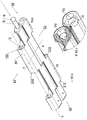
- a modular conveyor belt which is used for conveying various items, e.g. food items, in a conveying direction Y.
- the conveyor belt is adapted to be driven by at least one gear wheel (not shown).
- This conveyor belt comprises a plurality of modules 1, 1, ...1 arranged in succession and jointed together.
- Each module 1 comprises an intermediate section 2 which extends along an axis X (transverse to the direction Y of movement of the belt).
- the intermediate section 2 has: a top surface 21 for supporting items to be conveyed, a front side 23, a rear side 24, a first lateral side 25 and a second lateral side 26.
- a first plurality of projections or connection ends or hinge rings 31a, 31 are provided on the front side 23 of the intermediate section 2 and extend in the conveying direction Y.
- the hinge rings 31 a, 31 define conveying surfaces substantially coplanar with the conveying surface of the intermediate section 2 of the module 1.
- the hinge rings 31a, 31 of such first plurality have a pair of side walls 311, 312 which define their transverse dimension and have holes 4a, 4 aligned along a single axis, parallel to the transverse axis X, for receiving a first connecting pin 8.
- the connecting pin 8 which will be better described below, has a first end, or head, 81 and a second end, or tail, 82.
- a second plurality of projections or connection ends or hinge rings 32 are provided on the rear side 24 of the intermediate section 2 of the module 1 and extend in the longitudinal direction Y (but opposite to the first plurality of projections or connection ends or hinge rings 31a, 31).
- the second plurality of projections or connection ends or hinge rings 32 also define conveying surfaces substantially coplanar with the conveying surface of the intermediate section 2 of the module 1.
- the hinge rings 32, 32 of such second plurality have a pair of side walls 321, 322 which define their transverse dimension and have holes 5 aligned along a single axis, parallel to the transverse axis X, for receiving a second connecting pin 8.
- the first and second hinge rings 31, 31 a, 32 have mating profiles, such that the first hinge ring 31 a, 31 of the module 1 may be in intermeshing relationship with the second hinge rings 32 of a similar adjacent module, and that the second hinge rings 32 of the module may be in intermeshing relationship with the first hinge rings (31a, 31) of a second similar adjacent module.
- the holes 4, 4a, 5 of the hinge rings 31, 31a, 32 have a substantially and/or generally round section and the connecting pins 8 have a substantially and/or generally cylindrical shape (excepting the end 81 as more clearly explained below).
- the hole 4a of at least one lateral hinge ring 31a of at least one of the two pluralities of hinge rings 31, 31a; 32 has an inner portion, or seat 41, whose cross section is wider than the rest of the hole 4a, an the connecting pin 8 has a first end, or head, 81 having an enlarged section as compared to the rest of the pin 8 to allow snap-fit insertion of the end 81 of the pin 8 into the portion 41 having a wider section.
- the head 8 and the seat 41 have such shapes that the snap-fit insertion of the head 81 into the seat 41 is obtained by axially pushing the pin 8, with no need for rotary movements.
- the head 81 has the shape of a sphere or a spherical cap, with a maximum transverse dimension greater than the transverse dimension of the rest of the pin 8.
- the rest of the pin 8 has a constant section, and particularly has a cylindrical shape.
- the seat 41 has a shape that mates the shape of the head 81.
- the second end 82 of the pin 8 i.e. the end opposite to that with the enlarged section 81, is introduced into the hole 4a, at the lateral hinge ring 31a.
- the pin 8 is slid into the holes 4, 5 of the interconnected modules on the same line, until the head 81 enters the hole 4a of the lateral hinge ring 31a.
- the pin 8 is removed by simply exerting a pressure with a tip on the second end, or tail, 82 of the pin 8, to thereby force the head 81 out of the seat 41.
- the above described arrangement provides the advantage that the pin 8 is locked in a safe but reversible manner.
- the module 1 is obtained by molding of thermoplastic materials, e.g. an acetal resin, whereas the pin 8 is made from a thermoplastic material, such as an acetal resin or polypropylene.
- thermoplastic materials e.g. an acetal resin
- the pin 8 is made from a thermoplastic material, such as an acetal resin or polypropylene.
- the holes 4, 4a, 5 have an inlet diameter of 3 mm with a tolerance of ⁇ 0.1 mm.
- the pin 8 may have a diameter of 2.9 mm, with a tolerance of ⁇ 0.1 mm and the head 81 has a maximum diameter of 3.3 mm, with a tolerance of ⁇ 0.1 mm and the seat 41 has a maximum transverse dimension of 3.3 mm, with a tolerance of ⁇ 0,1 mm.
Landscapes
- Engineering & Computer Science (AREA)
- Mechanical Engineering (AREA)
- Chain Conveyers (AREA)
Claims (2)
- Modulares Transportband, das dazu geeignet ist, durch mindestens ein Zahnrad getrieben zu werden, worin das genannte Transportband derart ausgebildet ist, dass es sich in einer Förderrichtung (Y) bewegt, wobei das genannte Band eine Mehrzahl von aufeinanderfolgenden, gegenseitig angelenkten Modulen (1, 1, ...1) umfasst, wobei jedes Modul (1) wiederum umfasst:a) einen sich entlang einer quer zu der genannten Förderrichtung (Y) verlaufenden Achse (X) erstreckenden Zwischenabschnitt (2), der eine Oberseite zur Unterstützung von zu fördernden Gegenständen (21), eine Stirnseite (23), eine Rückseite (24), eine erste seitliche Seite (25) sowie eine zweite seitliche Seite (26) hat;b) eine erste Mehrzahl von Gelenkringen (31a, 31):b1) die von der genannten Stirnseite (23) entlang der genannten Förderrichtung (Y) verlaufen;b2) die ein Paar von die Querabmessungen davon bestimmenden Seitenwänden (311,312) haben;b3) die entlang einer zu der genannten Querachse (X) parallel verlaufenden einzigen Achse ausgerichtete Bohrungen (4a, 4) zur Aufnahme eines ersten Verbindungsstift (8) haben;c) eine zweite Mehrzahl von Gelenkringen (32):c1) die von der genannten Rückseite (24) entlang der genannten Förderrichtung (Y) verlaufen;c2) die ein Paar von die Querabmessungen davon bestimmenden Seitenwänden (321,322) haben;c3) die sich entlang einer zu der genannten Querachse (X) parallel verlaufenden einzigen Achse erstreckende Bohrungen (5) zur Aufnahme eines ersten Verbindungsstifts (8) haben;d) wobei die genannten ersten und die genannten zweiten Gelenkringe (31a, 31, 32) Verbindungsprofile haben, so dass die ersten Gelenkringe (31a, 31) des genannten Moduls in ineinandergreifender Beziehung mit den zweiten Gelenkringen (32) eines ähnlichen, angrenzenden Moduls stehen können, und dass die zweiten Gelenkringe (32) des genannten Moduls in ineinandergreifender Beziehung mit den ersten Gelenkringen (31a, 31) eines ähnlichen, angrenzenden Moduls stehen können;e) die Bohrung mindestens eines seitlichen Gelenkrings (31a) mindestens einer der genannten beiden Mehrzahlen von Gelenkringen (31a, 31, 32) eine Bohrung (4a) hat, die eine innere Portion (41) mit einem einen Sitz (41) bestimmenden erweiterten Querschnitt hat; wobei der genannte Verbindungsstift (8) ein Ende hat, das einen Kopf (81) mit einem erweiterten Querschnitt umfasst, so dass der genannte Kopf (81) in den genannten Sitz (41) des genannten seitlichen Gelenkrings (31a) eingerastet werden kann; wobei das genannte Einrasten des genannten Kopfs (81) durch eine lineare Bewegung des genannten Stifts (8) erzielt werden kann;dadurch gekennzeichnet, dass
der genannte Kopf (81) des Stifts (8) eine Kugel oder Kugelkalotte (81) ist und die höchste Querabmessung davon größer als die Querabmessung des restlichen Teils des Stifts (8) ist, worin der genannte Sitz (41) eine Form hat, die in die Form des genannten Kopfs (81) eingreift, so dass der genannte Stift (8) sicher aber reversibel gesperrt ist. - Band nach Anspruch 1, worin:die genannte erste Mehrzahl von Gelenkringen (31a, 31) Förderflächen bestimmt, die zu der Förderfläche des genannten Zwischenabschnitts (2) wesentlich koplanar sind, und worindie genannte zweite Mehrzahl von Gelenkringen (32) Förderflächen bestimmt, die zu der Förderfläche des genannten Zwischenabschnitts (2) wesentlich koplanar sind.
Applications Claiming Priority (1)
| Application Number | Priority Date | Filing Date | Title |
|---|---|---|---|
| ITAN20140197 | 2014-12-16 |
Publications (2)
| Publication Number | Publication Date |
|---|---|
| EP3040295A1 EP3040295A1 (de) | 2016-07-06 |
| EP3040295B1 true EP3040295B1 (de) | 2018-06-13 |
Family
ID=52472367
Family Applications (1)
| Application Number | Title | Priority Date | Filing Date |
|---|---|---|---|
| EP15199998.4A Active EP3040295B1 (de) | 2014-12-16 | 2015-12-15 | Modulares transportband |
Country Status (2)
| Country | Link |
|---|---|
| EP (1) | EP3040295B1 (de) |
| ES (1) | ES2685959T3 (de) |
Families Citing this family (1)
| Publication number | Priority date | Publication date | Assignee | Title |
|---|---|---|---|---|
| IT201800009505A1 (it) | 2018-10-16 | 2020-04-16 | Movex Spa | Tappeto di convogliamento a maglie articolate e relativo sistema di articolazione delle maglie |
Family Cites Families (5)
| Publication number | Priority date | Publication date | Assignee | Title |
|---|---|---|---|---|
| US5662211A (en) * | 1996-02-05 | 1997-09-02 | Rexnord Corporation | Conveyor chain with self retaining hinge pin with internal barbs |
| US6029802A (en) * | 1997-04-14 | 2000-02-29 | Rexnord Marbett S.P.A. | Link in a chain for conveying products |
| US7331447B2 (en) * | 2003-07-24 | 2008-02-19 | Habasit Ag | Rod retaining snap rod with enlarged retaining ring |
| US8978881B2 (en) * | 2009-10-29 | 2015-03-17 | Habasit Ag | Pivot rod and method of making thereof |
| ITRM20120430A1 (it) | 2012-09-07 | 2014-03-08 | System Plast S R L | Sistemi di trasporto con connettori e metodi di uso e realizzazione |
-
2015
- 2015-12-15 ES ES15199998.4T patent/ES2685959T3/es active Active
- 2015-12-15 EP EP15199998.4A patent/EP3040295B1/de active Active
Non-Patent Citations (1)
| Title |
|---|
| None * |
Also Published As
| Publication number | Publication date |
|---|---|
| EP3040295A1 (de) | 2016-07-06 |
| ES2685959T3 (es) | 2018-10-15 |
Similar Documents
| Publication | Publication Date | Title |
|---|---|---|
| EP1890951B1 (de) | Modulare förderbänder und befestigungen | |
| EP1687221B1 (de) | Kunststoffförderbandmodule mit seitenschutz | |
| US9663298B2 (en) | Conveyor belt module with shaped bottom surface | |
| CN106170450B (zh) | 模块化传送垫及其模块,以及链轮和传送系统 | |
| CN109843756B (zh) | 模块化传送机、传送机模块和联接模块化传送机的模块的方法 | |
| US6662938B2 (en) | Locking arrangement for releasably locking a transverse rod to a chain link | |
| AU2010235898A1 (en) | Link Chain | |
| US6644466B2 (en) | Platform-top radius belt and modules | |
| US8978881B2 (en) | Pivot rod and method of making thereof | |
| KR20160067871A (ko) | 컨베이어용 슬랫 | |
| WO2003040010A2 (en) | Polymer hinge pins in modular conveyor belts | |
| US12296448B2 (en) | System for fixing push rods to a chain | |
| EP3040295A1 (de) | Modulares transportband | |
| US8220620B2 (en) | Load-carrying conveyor chain | |
| CN105143071B (zh) | 输送带和用于输送带的平台 | |
| US10647512B2 (en) | Drive and sideguard belt insert for a modular plastic conveyor belt | |
| EP3105153B1 (de) | Förderer zum transport von produkten | |
| EP3640163B1 (de) | Gelenkverbindungsförderband und entsprechendes gelenkverbindungssystem | |
| US12240703B2 (en) | Modular conveyor belt with dedicated access module | |
| CA2973599C (en) | Conveyor belt module with stepped hinge passageway | |
| IT201900004020U1 (it) | Modulo per un trasportatore e relativo perno di collegamento dei componenti di ciascun modulo | |
| WO2008020755A2 (en) | Chain module for a modular chain conveyor, modular conveyor and conveying system provided with a modular chain conveyor | |
| EP2703321A1 (de) | Glied für Förderkette, Förderkette und Verfahren zu deren Montage | |
| ITMO20070325A1 (it) | Nastro modulare per trasportatore con sponde. |
Legal Events
| Date | Code | Title | Description |
|---|---|---|---|
| PUAI | Public reference made under article 153(3) epc to a published international application that has entered the european phase |
Free format text: ORIGINAL CODE: 0009012 |
|
| AK | Designated contracting states |
Kind code of ref document: A1 Designated state(s): AL AT BE BG CH CY CZ DE DK EE ES FI FR GB GR HR HU IE IS IT LI LT LU LV MC MK MT NL NO PL PT RO RS SE SI SK SM TR |
|
| AX | Request for extension of the european patent |
Extension state: BA ME |
|
| 17P | Request for examination filed |
Effective date: 20161228 |
|
| RBV | Designated contracting states (corrected) |
Designated state(s): AL AT BE BG CH CY CZ DE DK EE ES FI FR GB GR HR HU IE IS IT LI LT LU LV MC MK MT NL NO PL PT RO RS SE SI SK SM TR |
|
| 17Q | First examination report despatched |
Effective date: 20170623 |
|
| GRAP | Despatch of communication of intention to grant a patent |
Free format text: ORIGINAL CODE: EPIDOSNIGR1 |
|
| INTG | Intention to grant announced |
Effective date: 20180131 |
|
| GRAS | Grant fee paid |
Free format text: ORIGINAL CODE: EPIDOSNIGR3 |
|
| GRAA | (expected) grant |
Free format text: ORIGINAL CODE: 0009210 |
|
| AK | Designated contracting states |
Kind code of ref document: B1 Designated state(s): AL AT BE BG CH CY CZ DE DK EE ES FI FR GB GR HR HU IE IS IT LI LT LU LV MC MK MT NL NO PL PT RO RS SE SI SK SM TR |
|
| REG | Reference to a national code |
Ref country code: GB Ref legal event code: FG4D |
|
| REG | Reference to a national code |
Ref country code: CH Ref legal event code: EP Ref country code: AT Ref legal event code: REF Ref document number: 1008274 Country of ref document: AT Kind code of ref document: T Effective date: 20180615 |
|
| REG | Reference to a national code |
Ref country code: DE Ref legal event code: R096 Ref document number: 602015012186 Country of ref document: DE |
|
| REG | Reference to a national code |
Ref country code: IE Ref legal event code: FG4D |
|
| REG | Reference to a national code |
Ref country code: NL Ref legal event code: FP |
|
| REG | Reference to a national code |
Ref country code: ES Ref legal event code: FG2A Ref document number: 2685959 Country of ref document: ES Kind code of ref document: T3 Effective date: 20181015 |
|
| REG | Reference to a national code |
Ref country code: LT Ref legal event code: MG4D |
|
| PG25 | Lapsed in a contracting state [announced via postgrant information from national office to epo] |
Ref country code: BG Free format text: LAPSE BECAUSE OF FAILURE TO SUBMIT A TRANSLATION OF THE DESCRIPTION OR TO PAY THE FEE WITHIN THE PRESCRIBED TIME-LIMIT Effective date: 20180913 Ref country code: FI Free format text: LAPSE BECAUSE OF FAILURE TO SUBMIT A TRANSLATION OF THE DESCRIPTION OR TO PAY THE FEE WITHIN THE PRESCRIBED TIME-LIMIT Effective date: 20180613 Ref country code: SE Free format text: LAPSE BECAUSE OF FAILURE TO SUBMIT A TRANSLATION OF THE DESCRIPTION OR TO PAY THE FEE WITHIN THE PRESCRIBED TIME-LIMIT Effective date: 20180613 Ref country code: NO Free format text: LAPSE BECAUSE OF FAILURE TO SUBMIT A TRANSLATION OF THE DESCRIPTION OR TO PAY THE FEE WITHIN THE PRESCRIBED TIME-LIMIT Effective date: 20180913 Ref country code: CY Free format text: LAPSE BECAUSE OF FAILURE TO SUBMIT A TRANSLATION OF THE DESCRIPTION OR TO PAY THE FEE WITHIN THE PRESCRIBED TIME-LIMIT Effective date: 20180613 Ref country code: LT Free format text: LAPSE BECAUSE OF FAILURE TO SUBMIT A TRANSLATION OF THE DESCRIPTION OR TO PAY THE FEE WITHIN THE PRESCRIBED TIME-LIMIT Effective date: 20180613 |
|
| PG25 | Lapsed in a contracting state [announced via postgrant information from national office to epo] |
Ref country code: RS Free format text: LAPSE BECAUSE OF FAILURE TO SUBMIT A TRANSLATION OF THE DESCRIPTION OR TO PAY THE FEE WITHIN THE PRESCRIBED TIME-LIMIT Effective date: 20180613 Ref country code: GR Free format text: LAPSE BECAUSE OF FAILURE TO SUBMIT A TRANSLATION OF THE DESCRIPTION OR TO PAY THE FEE WITHIN THE PRESCRIBED TIME-LIMIT Effective date: 20180914 Ref country code: HR Free format text: LAPSE BECAUSE OF FAILURE TO SUBMIT A TRANSLATION OF THE DESCRIPTION OR TO PAY THE FEE WITHIN THE PRESCRIBED TIME-LIMIT Effective date: 20180613 Ref country code: LV Free format text: LAPSE BECAUSE OF FAILURE TO SUBMIT A TRANSLATION OF THE DESCRIPTION OR TO PAY THE FEE WITHIN THE PRESCRIBED TIME-LIMIT Effective date: 20180613 |
|
| REG | Reference to a national code |
Ref country code: AT Ref legal event code: MK05 Ref document number: 1008274 Country of ref document: AT Kind code of ref document: T Effective date: 20180613 |
|
| PG25 | Lapsed in a contracting state [announced via postgrant information from national office to epo] |
Ref country code: SK Free format text: LAPSE BECAUSE OF FAILURE TO SUBMIT A TRANSLATION OF THE DESCRIPTION OR TO PAY THE FEE WITHIN THE PRESCRIBED TIME-LIMIT Effective date: 20180613 Ref country code: RO Free format text: LAPSE BECAUSE OF FAILURE TO SUBMIT A TRANSLATION OF THE DESCRIPTION OR TO PAY THE FEE WITHIN THE PRESCRIBED TIME-LIMIT Effective date: 20180613 Ref country code: CZ Free format text: LAPSE BECAUSE OF FAILURE TO SUBMIT A TRANSLATION OF THE DESCRIPTION OR TO PAY THE FEE WITHIN THE PRESCRIBED TIME-LIMIT Effective date: 20180613 Ref country code: EE Free format text: LAPSE BECAUSE OF FAILURE TO SUBMIT A TRANSLATION OF THE DESCRIPTION OR TO PAY THE FEE WITHIN THE PRESCRIBED TIME-LIMIT Effective date: 20180613 Ref country code: AT Free format text: LAPSE BECAUSE OF FAILURE TO SUBMIT A TRANSLATION OF THE DESCRIPTION OR TO PAY THE FEE WITHIN THE PRESCRIBED TIME-LIMIT Effective date: 20180613 Ref country code: IS Free format text: LAPSE BECAUSE OF FAILURE TO SUBMIT A TRANSLATION OF THE DESCRIPTION OR TO PAY THE FEE WITHIN THE PRESCRIBED TIME-LIMIT Effective date: 20181013 Ref country code: PL Free format text: LAPSE BECAUSE OF FAILURE TO SUBMIT A TRANSLATION OF THE DESCRIPTION OR TO PAY THE FEE WITHIN THE PRESCRIBED TIME-LIMIT Effective date: 20180613 |
|
| PG25 | Lapsed in a contracting state [announced via postgrant information from national office to epo] |
Ref country code: IT Free format text: LAPSE BECAUSE OF FAILURE TO SUBMIT A TRANSLATION OF THE DESCRIPTION OR TO PAY THE FEE WITHIN THE PRESCRIBED TIME-LIMIT Effective date: 20180613 Ref country code: SM Free format text: LAPSE BECAUSE OF FAILURE TO SUBMIT A TRANSLATION OF THE DESCRIPTION OR TO PAY THE FEE WITHIN THE PRESCRIBED TIME-LIMIT Effective date: 20180613 |
|
| REG | Reference to a national code |
Ref country code: DE Ref legal event code: R097 Ref document number: 602015012186 Country of ref document: DE |
|
| PLBE | No opposition filed within time limit |
Free format text: ORIGINAL CODE: 0009261 |
|
| STAA | Information on the status of an ep patent application or granted ep patent |
Free format text: STATUS: NO OPPOSITION FILED WITHIN TIME LIMIT |
|
| 26N | No opposition filed |
Effective date: 20190314 |
|
| PG25 | Lapsed in a contracting state [announced via postgrant information from national office to epo] |
Ref country code: DK Free format text: LAPSE BECAUSE OF FAILURE TO SUBMIT A TRANSLATION OF THE DESCRIPTION OR TO PAY THE FEE WITHIN THE PRESCRIBED TIME-LIMIT Effective date: 20180613 Ref country code: SI Free format text: LAPSE BECAUSE OF FAILURE TO SUBMIT A TRANSLATION OF THE DESCRIPTION OR TO PAY THE FEE WITHIN THE PRESCRIBED TIME-LIMIT Effective date: 20180613 |
|
| REG | Reference to a national code |
Ref country code: CH Ref legal event code: PL |
|
| PG25 | Lapsed in a contracting state [announced via postgrant information from national office to epo] |
Ref country code: LU Free format text: LAPSE BECAUSE OF NON-PAYMENT OF DUE FEES Effective date: 20181215 Ref country code: MC Free format text: LAPSE BECAUSE OF FAILURE TO SUBMIT A TRANSLATION OF THE DESCRIPTION OR TO PAY THE FEE WITHIN THE PRESCRIBED TIME-LIMIT Effective date: 20180613 |
|
| REG | Reference to a national code |
Ref country code: IE Ref legal event code: MM4A |
|
| REG | Reference to a national code |
Ref country code: BE Ref legal event code: MM Effective date: 20181231 |
|
| PG25 | Lapsed in a contracting state [announced via postgrant information from national office to epo] |
Ref country code: FR Free format text: LAPSE BECAUSE OF NON-PAYMENT OF DUE FEES Effective date: 20181231 Ref country code: IE Free format text: LAPSE BECAUSE OF NON-PAYMENT OF DUE FEES Effective date: 20181215 |
|
| PG25 | Lapsed in a contracting state [announced via postgrant information from national office to epo] |
Ref country code: BE Free format text: LAPSE BECAUSE OF NON-PAYMENT OF DUE FEES Effective date: 20181231 Ref country code: AL Free format text: LAPSE BECAUSE OF FAILURE TO SUBMIT A TRANSLATION OF THE DESCRIPTION OR TO PAY THE FEE WITHIN THE PRESCRIBED TIME-LIMIT Effective date: 20180613 |
|
| PG25 | Lapsed in a contracting state [announced via postgrant information from national office to epo] |
Ref country code: LI Free format text: LAPSE BECAUSE OF NON-PAYMENT OF DUE FEES Effective date: 20181231 Ref country code: CH Free format text: LAPSE BECAUSE OF NON-PAYMENT OF DUE FEES Effective date: 20181231 |
|
| PG25 | Lapsed in a contracting state [announced via postgrant information from national office to epo] |
Ref country code: MT Free format text: LAPSE BECAUSE OF NON-PAYMENT OF DUE FEES Effective date: 20181215 |
|
| PG25 | Lapsed in a contracting state [announced via postgrant information from national office to epo] |
Ref country code: TR Free format text: LAPSE BECAUSE OF FAILURE TO SUBMIT A TRANSLATION OF THE DESCRIPTION OR TO PAY THE FEE WITHIN THE PRESCRIBED TIME-LIMIT Effective date: 20180613 |
|
| PG25 | Lapsed in a contracting state [announced via postgrant information from national office to epo] |
Ref country code: PT Free format text: LAPSE BECAUSE OF FAILURE TO SUBMIT A TRANSLATION OF THE DESCRIPTION OR TO PAY THE FEE WITHIN THE PRESCRIBED TIME-LIMIT Effective date: 20180613 |
|
| PG25 | Lapsed in a contracting state [announced via postgrant information from national office to epo] |
Ref country code: MK Free format text: LAPSE BECAUSE OF NON-PAYMENT OF DUE FEES Effective date: 20180613 Ref country code: HU Free format text: LAPSE BECAUSE OF FAILURE TO SUBMIT A TRANSLATION OF THE DESCRIPTION OR TO PAY THE FEE WITHIN THE PRESCRIBED TIME-LIMIT; INVALID AB INITIO Effective date: 20151215 |
|
| P01 | Opt-out of the competence of the unified patent court (upc) registered |
Effective date: 20230626 |
|
| PGFP | Annual fee paid to national office [announced via postgrant information from national office to epo] |
Ref country code: GB Payment date: 20251229 Year of fee payment: 11 |
|
| PGFP | Annual fee paid to national office [announced via postgrant information from national office to epo] |
Ref country code: NL Payment date: 20251226 Year of fee payment: 11 |
|
| PGFP | Annual fee paid to national office [announced via postgrant information from national office to epo] |
Ref country code: ES Payment date: 20260102 Year of fee payment: 11 |
|
| PGFP | Annual fee paid to national office [announced via postgrant information from national office to epo] |
Ref country code: DE Payment date: 20251229 Year of fee payment: 11 |