EP2005231B1 - Vorrichtung zur abfangung von lichtwellenleiterkabeln - Google Patents
Vorrichtung zur abfangung von lichtwellenleiterkabeln Download PDFInfo
- Publication number
- EP2005231B1 EP2005231B1 EP07722896.3A EP07722896A EP2005231B1 EP 2005231 B1 EP2005231 B1 EP 2005231B1 EP 07722896 A EP07722896 A EP 07722896A EP 2005231 B1 EP2005231 B1 EP 2005231B1
- Authority
- EP
- European Patent Office
- Prior art keywords
- cable
- slide
- slide part
- guide
- sealing body
- Prior art date
- Legal status (The legal status is an assumption and is not a legal conclusion. Google has not performed a legal analysis and makes no representation as to the accuracy of the status listed.)
- Active
Links
Images


Classifications
-
- H—ELECTRICITY
- H02—GENERATION; CONVERSION OR DISTRIBUTION OF ELECTRIC POWER
- H02G—INSTALLATION OF ELECTRIC CABLES OR LINES, OR OF COMBINED OPTICAL AND ELECTRIC CABLES OR LINES
- H02G15/00—Cable fittings
- H02G15/007—Devices for relieving mechanical stress
-
- G—PHYSICS
- G02—OPTICS
- G02B—OPTICAL ELEMENTS, SYSTEMS OR APPARATUS
- G02B6/00—Light guides; Structural details of arrangements comprising light guides and other optical elements, e.g. couplings
- G02B6/44—Mechanical structures for providing tensile strength and external protection for fibres, e.g. optical transmission cables
- G02B6/4439—Auxiliary devices
- G02B6/4471—Terminating devices ; Cable clamps
- G02B6/44785—Cable clamps
-
- G—PHYSICS
- G02—OPTICS
- G02B—OPTICAL ELEMENTS, SYSTEMS OR APPARATUS
- G02B6/00—Light guides; Structural details of arrangements comprising light guides and other optical elements, e.g. couplings
- G02B6/44—Mechanical structures for providing tensile strength and external protection for fibres, e.g. optical transmission cables
- G02B6/4439—Auxiliary devices
- G02B6/4471—Terminating devices ; Cable clamps
- G02B6/4477—Terminating devices ; Cable clamps with means for strain-relieving to interior strengths element
Definitions
- the invention relates to a device for the interception of optical waveguide cables according to the preamble of patent claim 1.
- connection points or branch points for optical fiber cables, wherein at the connection points or branch points splices between guided in the optical fiber cables optical fibers are formed.
- the splices are stored in so-called cable sleeves, wherein the optical fiber cables are inserted via a sealing body of a cable sleeve in an interior of the cable sleeve.
- the optical fiber cables are trapped outside or inside the cable sleeve with respect to a tensile stress and optionally also torsional stress and bending stress, with special interception devices serving this purpose.
- the present invention relates to a device for intercepting optical waveguide cables in the region of a sealing body of a cable sleeve, namely within an inner space bounded by the cable sleeve.
- a device for the interception of optical fiber cables according to the preamble of the claim is known from WO 97/12268 A1 known.
- the present invention is based on the problem to provide a novel device for the interception of fiber optic cables.
- the device can be adapted to different cable diameter of the intercepted fiber optic cable.
- the slide parts relative to the mounting part adjustable so as to align the slide parts against a lateral surface of the fiber optic cable to be intercepted
- the guide parts relative to the slide parts are adjustable, so as to align the guide parts relative to the central elements of the intercepted fiber optic cable.
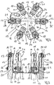
- Fig. 1 to 3 show different views of a device 10 according to the invention for the interception of optical fiber cables according to a first embodiment of the invention with a total of six intercepted at the device 10 optical fiber cables 11.
- the inventive device 10 serves to intercept the optical fiber cable 11 in an interior of a cable sleeve, not shown, wherein the Fiber optic cable 11 are introduced via insertion openings of a sealing body of the cable sleeve in the interior thereof.
- the device 10 has a mounting part 12, wherein the mounting part 12 can be fastened to the sealing body, not shown, of a cable sleeve.
- the mounting member 12 is annular in the embodiment shown and not shown fastening screws extending through introduced into the mounting part 12 holes 13, immovably fixed to the sealing body of the cable sleeve.
- the device 10 has a plurality of engaging on the mounting member 12 slide members 14.
- a total of six slide members 14 each slide member 14 of the individual support a single optical fiber cable 11 is used.
- Each of the slide parts 14 is to adjust the same to a cable diameter of each intercepted optical fiber cable within predetermined limits translationally adjustable relative to the mounting member 12, namely in the radial direction of the mounting member 12 and a sealing body of a cable sleeve to which the mounting member 12 is attached.
- each slide part 14 is assigned a guide part 15.
- Each guide member 15 is translationally adjustable relative to the corresponding slide member 14 within predetermined limits to adapt the guide members 15 to different cable diameters of the fiber optic cable 11 to be intercepted at the corresponding slide parts 14 , In the radial direction of the mounting part 12 and a non-illustrated sealing body of a cable sleeve to which the mounting member 12 is attached.
- the slide parts 14 can accordingly be displaced relative to the mounting part 12 so as to abut the same on an outer lateral surface of the optical fiber cable 11 to be intercepted and intercept the optical waveguide cables 11 on the slide parts 14.
- the guide parts 15 can be adjusted relative to the slide parts 14 in order to align the same exactly to be intercepted central elements 16 of the optical fiber cable 11, so that the central elements 16 must not be bent or bent for the purpose of interception.
- Each central element 16 of an optical waveguide cable 11 can therefore be intercepted centrally centered on the device 10 according to the invention.
- Each slide part 14 of the device 10 according to the invention has a base plate which has angled end portions 17 and 18 at two opposite ends in different directions.
- the first end portions 17 of the slide parts 14 are inserted into the U-shaped displays 19 of the mounting part 12 and slidably mounted in the same over the first end portions 17, the slide parts 14 on the mounting part 12, namely at U-shaped exhibitions 19 of the mounting part.
- the slide parts 14 can be adapted to the cable diameter of an optical waveguide cable 11 to be intercepted, in such a way that a middle section 20 of the slide parts 14 can be brought into abutment against a cable sheathing of the optical fiber cable 11 to be intercepted.
- the relative position of a slide member 14 relative to the mounting member 12 can be fixed via a locking screw, not shown, extending through a hole in the U-shaped exhibition 19 and through a slot within the first end portion 17 of the slide member 14.
- a locking screw not shown
- the slide member 14 can be moved translationally relative to the U-shaped exhibition 19 of the central part 14, in which case the position of the locking screw relative to the slot of the first end portion 17 of the slide member 14 changes.
- the set screw tightened the same fixes the relative position of the slide member 14 to the mounting part 12th
- the guide member 15 is slidably mounted in the translatory direction at the second end portion 18 of the corresponding slide member 14, in such a way that an engaging on the guide member 15 locking screw 21 is guided in a slot of the second end portion 18 of the corresponding slide member 14, wherein when dissolved locking screw 21 the same and thus the corresponding guide member 21 can be moved translationally relative to the slide member 14.
- a cable clamp 22 For the purpose of intercepting the optical waveguide cables 11, the same are fastened in the illustrated exemplary embodiment via a cable clamp 22 to the middle section 20 of a slide part 14.
- Such cable clamps are also referred to as hose clamps.
- cable clamps and cable ties for attachment and thus interception of the optical waveguide 11 can be used on the slide parts 14.
- the guide parts 15 have, as best Fig. 3 can be removed, via a recess into which a central element 16 of an optical fiber cable 11 can be inserted to intercept the same.
- this bore of the guide member 15 can be aligned exactly centered to be intercepted central element 16 of the optical fiber cable, so that the central element 16 without any bending or deflection straight into the hole of the respective management part can be introduced.
- a fixing screw 23 serves to fix the central element 16 in the bore of the guide part 15.
- Each central element 16 of an optical fiber cable 11 can be grounded individually.
- a grounding strap 24 is used, which engages with a first end on the mounting part 12 of the device 10 and with a second end on the guide part 15, in which the respective central element 16 is intercepted.
- the central elements 16 of three optical waveguide cables 11 are earthed individually via a grounding strap 24 in each case.
- a plurality of optical waveguide cables and their central elements can be individually intercepted, wherein on the one hand the slide parts 14, which respectively serve the individual interception of an optical waveguide cable 11, are individually translationally displaceable relative to the mounting part 12, and on the other hand the guide parts 15 , which serve to intercept the central elements 16 of the respective optical waveguide cable 11, are translationally adjustable relative to the respective slide part 14 in order to align them centrally with the central element to be intercepted.
- the device according to the invention can be continuously adapted to different diameters of the optical waveguide cable and thereby different positions of the central elements 16.
- the slide parts 14 of the device 10 according to the invention are arranged approximately uniformly distributed over the circumference of the annular mounting part 12.
- the slide members 14 together with the annular mounting member 12 a star-shaped interceptor, wherein, as already mentioned, on the one hand, the slide members 14 can be adjusted relative to the mounting member 12 in the radial direction continuously, and on the other hand, the guide members 15 relative to the respective slide member 14 and thus to Mounting part 12 can be adjusted continuously in the radial direction.
- tensile forces, shear forces, bending forces and torsional forces acting on the optical waveguide cables 11 and their central elements 16 can be compensated or intercepted.
- Fig. 4 shows a section of a device according to the invention 25 for the interception of optical fiber cables according to a second embodiment of the invention, together with three intercepted at the device 25 optical fiber cables 11th
- Fig. 4 differs from the embodiment of Fig. 1 to 3 only in that the slide parts 14 in the region of the second end portions 18 downwardly angled portions or tabs 26 which serve to prevent rotation of the guide members 15 at the respective second end portion 18 of a slide member 14. As a result, the ease of installation can be increased.
Landscapes
- Physics & Mathematics (AREA)
- General Physics & Mathematics (AREA)
- Optics & Photonics (AREA)
- Light Guides In General And Applications Therefor (AREA)
- Mechanical Coupling Of Light Guides (AREA)
- Apparatus For Radiation Diagnosis (AREA)
- Installation Of Indoor Wiring (AREA)
Description
- Die Erfindung betrifft eine Vorrichtung zur Abfangung von Lichtwellenleiterkabeln nach dem Oberbegriff des Patentanspruchs 1.
- Beim Aufbau von Lichtwellenleiterkabelnetzen ist es erforderlich, sogenannte Verbindungsstellen bzw. Abzweigstellen für Lichtwellenleiterkabel vorzusehen, wobei an den Verbindungsstellen bzw. Abzweigstellen Spleiße zwischen in den Lichtwellenleiterkabeln geführten Lichtwellenleitern ausgebildet werden. Zum Schutz der Spleißverbindungen an den Verbindungsstellen bzw. Abzweigstellen werden die Spleißverbindungen in sogenannten Kabelmuffen abgelegt, wobei die Lichtwellenleiterkabel über einen Dichtkörper einer Kabelmuffe in einen Innenraum der Kabelmuffe eingeführt werden.
- Die Lichtwellenleiterkabel werden außerhalb bzw. innerhalb der Kabelmuffe gegenüber einer Zugbeanspruchung sowie gegebenenfalls auch Torsionsbeanspruchung und Biegebeanspruchung abgefangen, wobei hierzu spezielle Abfangvorrichtungen dienen. Die hier vorliegende Erfindung betrifft eine Vorrichtung zur Abfangung von Lichtwellenleiterkabeln im Bereich eines Dichtkörpers einer Kabelmuffe, nämlich innerhalb eines von der Kabelmuffe begrenzten Innenraums.
- Eine Vorrichtung zur Abfangung von Lichtwellenleiterkabeln nach dem Oberbegriff des Patentanspruchs ist aus der
WO 97/12268 A1 - Der hier vorliegenden Erfindung liegt das Problem zu Grunde, eine neuartige Vorrichtung zur Abfangung von Lichtwellenleiterkabeln zu schaffen.
- Dieses Problem wird durch eine Vorrichtung gemäß Patentanspruch 1 gelöst.
- An der erfindungsgemäßen Vorrichtung können mehrere Lichtwellenleiterkabel gegenüber einer Zugbeanspruchung, Torsionsbeanspruchung und Beigebeanspruchung individuell abgefangen werden, wobei die Vorrichtung an unterschiedliche Kabeldurchmesser der abzufangenden Lichtwellenleiterkabel angepasst werden kann. Zur Anpassung an die Kabeldurchmesser der Lichtwellenleiterkabel sind einerseits die Schieberteile gegenüber dem Montageteil verstellbar, um so die Schieberteile gegenüber einer Mantelfläche der abzufangenden Lichtwellenleiterkabel auszurichten, andererseits sind die Führungsteile gegenüber den Schieberteilen verstellbar, um so die Führungsteile gegenüber den Zentralelementen der abzufangenden Lichtwellenleiterkabel auszurichten.
- Bevorzugte Weiterbildungen der Erfindung ergeben sich aus den Unteransprüchen und der nachfolgenden Beschreibung.
- Ein Ausführungsbeispiel der Erfindung wird, ohne hierauf beschränkt zu sein, anhand der Zeichnung näher erläutert. In der Zeichnung zeigt:
- Fig. 1:
- eine perspektivische Ansicht einer erfindungsgemäßen Vorrichtung zur Abfangung von Lichtwellenleiterkabeln nach einem ersten Ausführungsbeispiel der Erfindung zusammen mit sechs an der Vorrichtung abgefangenen Lichtwellenleiterkabeln;
- Fig. 2:
- die erfindungsgemäße Vorrichtung zur Abfangung von Lichtwellenleiterkabeln der
Fig. 1 in Draufsicht; - Fig. 3:
- einen Querschnitt durch die erfindungsgemäße Vorrichtung zur Abfangung von Lichtwellenleiterkabeln der
Fig. 1 und2 entlang der Schnittlinie III-III inFig. 2 ; - Fig. 4:
- einen Ausschnitt aus einer erfindungsgemäßen Vorrichtung zur Abfangung von Lichtwellenleiterkabeln nach einem zweiten Ausführungsbeispiel der Efindung in einer Ansicht analog zu
Fig. 1 . - Nachfolgend wird die Erfindung unter Bezugnahme auf
Fig. 1 bis 3 in größerem Detail beschrieben. -
Fig. 1 bis 3 zeigen unterschiedliche Ansichten einer erfindungsgemäßen Vorrichtung 10 zur Abfangung von Lichtwellenleiterkabeln nach einem ersten Ausführungsbeispiel der Erfindung mit insgesamt sechs an der Vorrichtung 10 abgefangenen Lichtwellenleiterkabeln 11. Die erfindungsgemäße Vorrichtung 10 dient dabei der Abfangung der Lichtwellenleiterkabel 11 in einem Innenraum einer nicht-dargestellten Kabelmuffe, wobei die Lichtwellenleiterkabel 11 über Einführungsöffnungen eines Dichtkörpers der Kabelmuffe in den Innenraum derselben eingeführt werden. - Die erfindungsgemäße Vorrichtung 10 verfügt über ein Montageteil 12, wobei das Montageteil 12 am nicht-dargestellten Dichtkörper einer Kabelmuffe befestigbar ist. Das Montageteil 12 ist im gezeigten Ausführungsbeispiel ringförmig ausgebildet und über nicht-dargestellte Befestigungsschrauben, die sich durch in das Montageteil 12 eingebrachte Bohrungen 13 erstrecken, unverschiebbar am Dichtkörper der Kabelmuffe fixierbar.
- Neben dem ringförmigen Montageteil 12 verfügt die erfindungsgemäße Vorrichtung 10 über mehrere am Montageteil 12 angreifende Schieberteile 14. Im gezeigten Ausführungsbeispiel greifen am ringförmigen Montageteil 12 insgesamt sechs Schieberteile 14 an, wobei jedes Schieberteil 14 der individuellen Abfangung eines einzigen Lichtwellenleiterkabels 11 dient. Jedes der Schieberteile 14 ist zur Anpassung desselben an einen Kabeldurchmesser des jeweils abzufangenen Lichtwellenleiterkabels 11 innerhalb vorgegebener Grenzen translatorisch relativ zum Montageteil 12 verstellbar, nämlich in Radialrichtung des Montageteils 12 bzw. eines Dichtkörpers einer Kabelmuffe, an welchem das Montageteil 12 befestigt ist.
- Neben dem Montageteil 12 und den Schieberteilen 14 verfügt die erfindungsgemäße Vorrichtung 10 über Führungsteile 15, wobei im gezeigten Ausführungsbeispiel jedem Schieberteil 14 ein Führungsteil 15 zugeordnet ist. Jedes Führungsteil 15 dient der individuellen Abfangung eines Zentralelements 16 des am entsprechenden Schieberteil 14 abzufangenden Lichtwellenleiterkabels 11. Zur Anpassung der Führungsteile 15 an unterschiedliche Kabeldurchmesser der an den entsprechenden Schieberteilen 14 abzufangenden Lichtwellenleiterkabel 11 ist jedes Führungsteil 15 relativ zum entsprechenden Schieberteil 14 innerhalb vorgegebener Grenzen translatorisch verstellbar, und zwar in Radialrichtung des Montageteils 12 bzw. eines nicht-dargestellten Dichtkörpers einer Kabelmuffe, an welchem das Montageteil 12 befestigt ist.
- Bei der erfindungsgemäßen Vorrichtung 10 zur Abfangung von Lichtwellenleiterkabeln 11 können demnach einerseits die Schieberteile 14 relativ zum Montageteil 12 verstellt werden, um so dieselben an einer äußeren Mantelfläche der abzufangenden Lichtwellenleiterkabel 11 zur Anlage zu bringen und die Lichtwellenleiterkabel 11 an den Schieberteilen 14 abzufangen. Andererseits können die Führungsteile 15 relativ zu den Schieberteilen 14 verstellt werden, um dieselben exakt zu abzufangenden Zentralelementen 16 der Lichtwellenleiterkabel 11 auszurichten, so dass die Zentralelemente 16 zur Abfangung nicht verbogen bzw. abgeknickt werden müssen.
- Jedes Zentralelement 16 eines Lichtwellenleiterkabels 11 kann demnach an der erfindungsgemäßen Vorrichtung 10 mittig zentriert abgefangen werden.
- Mit Hilfe der erfindungsgemäßen Vorrichtung 10 können demnach auf die Lichtwellenleiterkabel 11 sowie deren Zentralelemente 16 einwirkende Zugkräfte, Schubkräfte, Biegekräfte und Torsionskräfte reduziert bzw. kompensiert werden.
- Jedes Schieberteil 14 der erfindungsgemäßen Vorrichtung 10 verfügt über eine Grundplatte, die an zwei gegenüberliegenden Enden in unterschiedliche Richtungen abgewinkelte Endabschnitte 17 und 18 aufweist. Über erste Endabschnitte 17 greifen die Schieberteile 14 am Montageteil 12 an, nämlich an U-förmigen Ausstellungen 19 des Montageteils 12. Die ersten Endabschnitte 17 der Schieberteile 14 sind in die U-förmigen Ausstellungen 19 des Montageteils 12 eingeführt und in denselben verschiebbar gelagert. Über diese Verschiebung können die Schieberteile 14 an den Kabeldurchmesser eines an denselben abzufangenden Lichtwellenleiterkabels 11 angepasst werden, und zwar derart, dass ein Mittelabschnitt 20 der Schieberteile 14 an einem Kabelmantel der abzufangenden Lichtwellenleiterkabel 11 zur Anlage gebracht werden kann.
- Die Relativposition eines Schieberteils 14 relativ zum Montageteil 12 kann über eine nicht-dargestellte Feststellschraube fixiert werden, die sich durch eine Bohrung in der U-förmigen Ausstellung 19 und durch ein Langloch innerhalb des ersten Endabschnitts 17 des Schieberteils 14 erstreckt. Bei gelöster Feststellschraube kann das Schieberteil 14 relativ zur U-förmigen Ausstellung 19 des Mittelteils 14 translatorisch verschoben werden, wobei sich dann die Position der Feststellschraube relativ zum Langloch der ersten Endabschnitts 17 des Schieberteils 14 verändert. Bei angezogener Feststellschraube fixiert dieselbe die Relativposition des Schieberteils 14 zum Montageteil 12.
- An dem relativ zum ersten Endabschnitt 17 der Schieberteile 14 in die entgegengesetzte Richtung gebogenen zweiten Endabschnitt 18 derselben greift im Bereich jedes Schieberteils 14 ein Führungsteil 15 an.
- Das Führungsteil 15 ist am zweiten Endabschnitt 18 des entsprechenden Schieberteils 14 in translatorischer Richtung verschiebbar gelagert, und zwar derart, dass eine am Führungsteil 15 angreifende Feststellschraube 21 in einem Langloch des zweiten Endabschnitts 18 des entsprechenden Schieberteils 14 geführt ist, wobei bei gelöster Feststellschraube 21 dieselbe und damit das entsprechende Führungsteil 21 relativ zum Schieberteil 14 translatorisch verschoben werden kann.
- Zur Abfangung der Lichtwellenleiterkabel 11 werden dieselben im gezeigten Ausführungsbeispiel über eine Kabelschelle 22 am Mittelabschnitt 20 eines Schieberteils 14 befestigt. Solche Kabelschellen werden auch als Schlauchschellen bezeichnet. Anstelle von Kabelschellen können auch Kabelbinder zur Befestigung und damit Abfangung der Lichtwellenleiter 11 an den Schieberteilen 14 verwendet werden.
- Die Führungsteile 15 verfügen, wie am besten
Fig. 3 entnommen werden kann, über eine Ausnehmung, in welche ein Zentralelement 16 eines Lichtwellenleiterkabels 11 eingeführt werden kann, um dasselbe abzufangen. Über die bereits oben beschriebene translatorische Verstellbarkeit des Führungsteils 15 relativ zum zweiten Endabschnitt 18 des Schieberteils 14 kann diese Bohrung des Führungsteils 15 exakt mittig zum abzufangenden Zentralelement 16 des Lichtwellenleiterkabels ausgerichtet werden, so dass das Zentralelement 16 ohne jegliche Abknickung bzw. Auslenkung geradlinig in die Bohrung des jeweiligen Führungsteils eingeführt werden kann. Eine Fixierschraube 23 dient dabei der Fixierung des Zentralelements 16 in der Bohrung des Führungsteils 15. - Jedes Zentralelement 16 eines Lichtwellenleiterkabels 11 kann individuell geerdet werden. Hierzu dient jeweils ein Erdungsband 24, welches mit einem ersten Ende am Montageteil 12 der Vorrichtung 10 und mit einem zweiten Ende am Führungsteil 15, in welchem das jeweilige Zentralelement 16 abgefangen ist, angreift. Im gezeigten Ausführungsbeispiel sind die Zentralelemente 16 von drei Lichtwellenleiterkabeln 11 über jeweils ein Erdungsband 24 individuell geerdet.
- Bei der erfindungsgemäßen Vorrichtung zur Abfangung von Lichtwellenleiterkabeln können demnach mehrere Lichtwellenleiterkabel sowie deren Zentralelemente individuell abgefangen werden, wobei einerseits die Schieberteile 14, die jeweils der individuellen Abfangung eines Lichtwellenleiterkabels 11 dienen, relativ zum Montageteil 12 individuell translatorisch verschiebbar sind, und wobei andererseits die Führungsteile 15, die der Abfangung der Zentralelemente 16 der jeweiligen Lichtwellenleiterkabel 11 dienen, relativ zum jeweiligen Schieberteil 14 translatorisch verstellbar sind, um dieselben mittig zum abzufangenden Zentralelement auszurichten. Hierdurch kann gewährleistet werden, dass ein Zentralelement 16 eines Lichtwellenleiterkabels 11 zur Abfangung nicht ausgeknickt werden muss. Vielmehr kann die erfindungsgemäße Vorrichtung stufenlos an unterschiedliche Durchmesser der Lichtwellenleiterkabel und dadurch bedingte unterschiedliche Positionen der Zentralelemente 16 angepasst werden.
- Die Schieberteile 14 der erfindungsgemäßen Vorrichtung 10 sind über den Umfang des ringförmigen Montageteils 12 in etwa gleichverteilt angeordnet. Die Schieberteile 14 bilden zusammen mit dem ringförmigen Montageteil 12 eine sternförmige Abfangvorrichtung, wobei, wie bereits erwähnt, einerseits die Schieberteile 14 relativ zum Montageteil 12 in radialer Richtung stufenlos verstellt werden können, und wobei andererseits die Führungsteile 15 relativ zum jeweiligen Schieberteil 14 und damit zum Montageteil 12 in radialer Richtung stufenlos verstellt werden können. Hierdurch können auf die Lichtwellenleiterkabel 11 sowie deren Zentralelemente 16 wirkende Zugkräfte, Schubkräfte, Biegekräfte und Torsionskräfte kompensiert bzw. abgefangen werden.
-
Fig. 4 zeigt einen Ausschnitt aus einer erfindungsgemäßen Vorrichtung 25 zur Abfangung von Lichtwellenleiterkabeln nach einem zweiten Ausführungsbeispiel der Erfindung zusammen mit drei an der Vorrichtung 25 abgefangenen Lichtwellenleiterkabeln 11. - Da das Ausführungsbeispiel der
Fig. 4 im wesentlichen dem Ausführungsbeispiel derFig. 1 bis 3 entspricht, werden zur Vermeidung unnötiger Widerholungen für gleiche Baugruppen gleiche Bezugsziffern verwendet und es wird nachfolgend nur auf die Details eingegangen, durch die sich das Ausführungsbeispiel derFig. 4 vom Ausführungsbeispiel derFig. 1 bis 3 unterscheidet. - Das Ausführungsbeispiel der
Fig. 4 unterscheidet sich vom Ausführungsbeispiel derFig. 1 bis 3 lediglich dadurch, dass die Schieberteile 14 im Bereich der zweiten Endabschnitte 18 nach unten abgewinkelte Abschnitte bzw. Laschen 26 aufweisen, die der Verdrehsicherung der Führungsteile 15 am jeweiligen zweiten Endabschnitt 18 eines Schieberteils 14 dienen. Hierdurch kann die Montagefreundlichkeit erhöht werden. -
- 10
- Vorrichtung
- 11
- Lichtwellenleiterkabel
- 12
- Montageteil
- 13
- Bohrung
- 14
- Schieberteil
- 15
- Führungsteil
- 16
- Zentralelement
- 17
- Endabschnitt
- 18
- Endabschnitt
- 19
- Ausstellung
- 20
- Mittelabschnitt
- 21
- Feststellschraube
- 22
- Kabelschelle
- 23
- Fixierschraube
- 24
- Erdungsband
- 25
- Vorrichtung
- 26
- Lasche
Claims (6)
- Vorrichtung zur Abfangung von Lichtwellenleiterkabeln im Bereich eines Dichtkörpers einer Kabelmuffe, nämlich innerhalb eines von der Kabelmuffe begrenzten Innenraums derselben, mit einem Montageteil (12), wobei das Montageteil (12) am Dichtkörper der Kabelmuffe befestigbar ist, mit mehreren am Montageteil (12) angreifenden Schieberteilen (14), wobei jedes Schieberteil (14) der individuellen Abfangung eines einzigen Lichtwellenleiterkabels dient und zur Anpassung desselben an einen Kabeldurchmesser des jeweils abzufangenden Lichtwellenleiterkabels in seiner Position relativ zum Montageteil (12) innerhalb vorgegebener Grenzen translatorisch verstellbar ist, und mit an den Schieberteilen (14) angreifenden Führungsteilen (15), wobei jedes Führungsteil (15) der individuellen Abfangung eines Zentralelements des am entsprechenden Schieberteil (14) abzufangenden Lichtwellenleiterkabels dient, dadurch gekennzeichnet, dass jedes Schieberteil eine Grundplatte aufweist, die an zwei gegenüberliegenden Enden in unterschiedliche Richtungen abgewinkelte Endabschnitte aufweist, wobei ein Schieberteil über einen ersten Endabschnitt (17) am Montageteil (12) angreift und über den ersten Endabschnitt relativ zum Montageteil in Radialrichtung des Dichtkörpers verstellbar ist, und wobei am zweiten Endabschnitt (18) des Schieberteils (14) ein Führungsteil (15) angreift, das an dem zweiten Endabschnitt zur mittigen Ausrichtung des Führungsteils an das Zentralelement des jeweils abzufangenden Lichtwellenleiterkabels in seiner Position relativ zum Schieberteil (14) in Radialrichtung des Dichtkörpers innerhalb vorgegebener Grenzen translatorisch verstellbar ist.
- Vorrichtung nach Anspruch 1, dadurch gekennzeichnet, dass das Montageteil (12) ringförmig ausgebildet und am Dichtkörper der Kabelmuffe unverschiebbar befestigbar ist.
- Vorrichtung nach Anspruch 1 oder 2, dadurch gekennzeichnet, dass an einem sich zwischen den beiden Endabschnitten (17, 18) des Schieberteils (14) erstreckenden Mittelabschnitt (20) des Schieberteils das an dem Schieberteil (14) abzufangende Lichtwellenleiterkabel vorzugsweise über eine Kabelschelle oder einen Kabelbinder befestigbar ist.
- Vorrichtung nach einem oder mehreren der Ansprüche 1 bis 3, dadurch gekennzeichnet, dass die Relativposition eines Schieberteils (14) zum Montageteil (12) über eine an dem ersten Endabschnitt (17) des Schieberteils (14) angreifende Feststellschraube fixierbar ist.
- Vorrichtung nach einem oder mehreren der Ansprüche 1 bis 4, dadurch gekennzeichnet, dass die Relativposition eines Führungsteils (15) zum entsprechenden Schieberteil (14) über eine an dem zweiten Endabschnitt (18) des Schieberteils angreifende Feststellschraube (21) fixierbar ist.
- Vorrichtung nach einem oder mehreren der Ansprüche 1 bis 5, dadurch gekennzeichnet, dass das Zentralelement jedes Lichtwellenleiterkabels über jeweils ein Erdungsband (24), welches einerseits am Montageteil (12) und andererseits am Führungsteil (15), in welchem das jeweilige Zentralelement abgefangen ist, angreift, individuell geerdet werden kann.
Applications Claiming Priority (2)
| Application Number | Priority Date | Filing Date | Title |
|---|---|---|---|
| DE202006006018U DE202006006018U1 (de) | 2006-04-11 | 2006-04-11 | Vorrichtung zur Abfangung von Lichtwellenleiterkabeln |
| PCT/EP2007/001520 WO2007118545A1 (de) | 2006-04-11 | 2007-02-22 | Vorrichtung zur abfangung von lichtwellenleiterkabeln |
Publications (2)
| Publication Number | Publication Date |
|---|---|
| EP2005231A1 EP2005231A1 (de) | 2008-12-24 |
| EP2005231B1 true EP2005231B1 (de) | 2017-07-26 |
Family
ID=36746493
Family Applications (1)
| Application Number | Title | Priority Date | Filing Date |
|---|---|---|---|
| EP07722896.3A Active EP2005231B1 (de) | 2006-04-11 | 2007-02-22 | Vorrichtung zur abfangung von lichtwellenleiterkabeln |
Country Status (7)
| Country | Link |
|---|---|
| US (1) | US7783152B2 (de) |
| EP (1) | EP2005231B1 (de) |
| CN (1) | CN101421654A (de) |
| AU (1) | AU2007237564B2 (de) |
| BR (1) | BRPI0710590A2 (de) |
| DE (1) | DE202006006018U1 (de) |
| WO (1) | WO2007118545A1 (de) |
Families Citing this family (15)
| Publication number | Priority date | Publication date | Assignee | Title |
|---|---|---|---|---|
| DE102007010863B4 (de) * | 2007-03-01 | 2009-01-08 | Adc Gmbh | Muffe für Lichtwellenleiter-Kabel |
| DE102007010855B4 (de) * | 2007-03-01 | 2009-01-08 | Adc Gmbh | Trägersystem für eine Verteilereinrichtung für Lichtwellenleiter |
| DE102007032186A1 (de) * | 2007-03-01 | 2008-12-18 | Adc Gmbh | Trägersystem zur Befestigung von Einrichtungen der Telekommunikations- und Datentechnik |
| DE102007010854B4 (de) * | 2007-03-01 | 2009-01-08 | Adc Gmbh | Konsole für eine Verteilereinrichtung für Lichtwellenleiter-Kabel |
| DE102007010853B4 (de) | 2007-03-01 | 2009-01-29 | Adc Gmbh | Verteilereinrichtung für Lichtwellenleiter |
| DE202007013984U1 (de) * | 2007-10-05 | 2007-12-06 | CCS Technology, Inc., Wilmington | Vorrichtung zur Abfangung von Lichtwellenleiterkabeln |
| DE202007014371U1 (de) * | 2007-10-12 | 2007-12-20 | CCS Technology, Inc., Wilmington | Vorrichtung zur Abfangung von Lichtwellenleiterkabeln |
| US8891930B2 (en) | 2012-08-10 | 2014-11-18 | Coring Cable Systems Llc | Fiber management frames having modular tray holder |
| US9983377B2 (en) | 2014-06-30 | 2018-05-29 | Corning Optical Communications LLC | Enclosure with combined strain relief and grounding |
| CN113348392B (zh) | 2019-01-22 | 2022-11-22 | 康普技术有限责任公司 | 用于电信机壳的电缆固定组件 |
| MX2022002923A (es) * | 2019-09-09 | 2022-07-19 | Preformed Line Products Co | Sistema de manejo de cables para un receptaculo de empalme y un receptaculo de empalme con un sistema de manejo de cables. |
| US20210165182A1 (en) * | 2019-11-29 | 2021-06-03 | Bce Inc. | Optical fiber splice closure and method of installing fiber optic cables |
| WO2021163340A1 (en) | 2020-02-11 | 2021-08-19 | Commscope Technologies Llc | Cable fixation devices and arrangements with improved installation and space utilization at telecommunications enclosures |
| US20220034356A1 (en) * | 2020-08-03 | 2022-02-03 | Preformed Line Products Co. | Ball peen bolt |
| FR3119686B1 (fr) * | 2021-02-05 | 2023-04-07 | Nexans | Système d’arrimage de câble au contenant d’un boîtier d’épissurage optique |
Family Cites Families (15)
| Publication number | Priority date | Publication date | Assignee | Title |
|---|---|---|---|---|
| DE3726719A1 (de) * | 1986-04-07 | 1989-02-23 | Siemens Ag | Vorrichtung zum anbringen einer mechanischen verbindung am kabelmantel eines optischen kabels |
| DE3726718A1 (de) | 1986-04-07 | 1989-02-23 | Siemens Ag | Vorrichtung zum anbringen einer mechanischen verbindung am kabelmantel eines optischen kabels |
| US4805979A (en) * | 1987-09-04 | 1989-02-21 | Minnesota Mining And Manufacturing Company | Fiber optic cable splice closure |
| US4991928A (en) * | 1990-02-20 | 1991-02-12 | Siecor Corporation | Movable clamp for fiber optic enclosures |
| GB9212624D0 (en) * | 1992-06-15 | 1992-07-29 | Raychem Sa Nv | Cable sealing device |
| DE4231181C1 (en) * | 1992-09-17 | 1993-08-26 | Siemens Ag, 8000 Muenchen, De | Cable restraint for fibre=optic cable distribution box - comprises U=shaped fixing shell fastened to rail which mounts screw for fixing cable central strain element |
| ATE187256T1 (de) * | 1994-07-21 | 1999-12-15 | Rxs Schrumpftech Garnituren | Abfangsvorrichtung für optische kabel |
| US5793921A (en) * | 1995-03-20 | 1998-08-11 | Psi Telecommunications, Inc. | Kit and method for converting a conductive cable closure to a fiber optic cable closure |
| DE69637538D1 (de) * | 1995-09-29 | 2008-07-03 | Minnesota Mining & Mfg | |
| DE59703529D1 (de) * | 1996-03-20 | 2001-06-21 | Rxs Ges Fuer Vermoegensverwalt | Kabelmuffe |
| US5824961A (en) * | 1997-04-30 | 1998-10-20 | Lucent Technologies Inc. | Central strength member anchor for optical fiber cables |
| CN1307444C (zh) * | 2001-05-25 | 2007-03-28 | 预制管线产品公司 | 光纤电缆罩和组件 |
| DE10338848A1 (de) | 2003-08-20 | 2005-03-17 | CCS Technology, Inc., Wilmington | Abfangvorrichtung für optische Kabel, Kabelmuffe mit einer solchen Abfangvorrichtung und Verfahren zur Bereitstellung einer Abfangung für optische Kabel unter Verwendung einer solchen Abfangvorrichtung |
| DE202005009932U1 (de) * | 2005-06-22 | 2005-11-24 | CCS Technology, Inc., Wilmington | Vorrichtung zur Abfangung von in Mikroducts geführten Mikrokabeln sowie der Mikroducts |
| US7711236B2 (en) * | 2007-10-22 | 2010-05-04 | Adc Telecommunications, Inc. | Fiber optic cable clamp |
-
2006
- 2006-04-11 DE DE202006006018U patent/DE202006006018U1/de not_active Expired - Lifetime
-
2007
- 2007-02-22 EP EP07722896.3A patent/EP2005231B1/de active Active
- 2007-02-22 WO PCT/EP2007/001520 patent/WO2007118545A1/de not_active Ceased
- 2007-02-22 CN CNA2007800129858A patent/CN101421654A/zh active Pending
- 2007-02-22 BR BRPI0710590-8A patent/BRPI0710590A2/pt not_active IP Right Cessation
- 2007-02-22 AU AU2007237564A patent/AU2007237564B2/en not_active Ceased
-
2008
- 2008-10-10 US US12/249,480 patent/US7783152B2/en active Active
Non-Patent Citations (1)
| Title |
|---|
| None * |
Also Published As
| Publication number | Publication date |
|---|---|
| EP2005231A1 (de) | 2008-12-24 |
| US7783152B2 (en) | 2010-08-24 |
| AU2007237564A1 (en) | 2007-10-25 |
| BRPI0710590A2 (pt) | 2011-08-16 |
| CN101421654A (zh) | 2009-04-29 |
| AU2007237564B2 (en) | 2011-09-29 |
| US20090087158A1 (en) | 2009-04-02 |
| DE202006006018U1 (de) | 2006-07-13 |
| WO2007118545A1 (de) | 2007-10-25 |
Similar Documents
| Publication | Publication Date | Title |
|---|---|---|
| EP2005231B1 (de) | Vorrichtung zur abfangung von lichtwellenleiterkabeln | |
| EP1736807B1 (de) | Vorrichtung zur Abfangung von in Mikroducts geführten Mikrokabeln sowie der Mikroducts | |
| EP1656720B1 (de) | Abfangvorrichtung für optische kabel sowie kabelmuffe | |
| EP0290989A2 (de) | An einer Montageplatte schwimmend befestigte Steckkupplung | |
| DE102007010854B4 (de) | Konsole für eine Verteilereinrichtung für Lichtwellenleiter-Kabel | |
| EP3699660A2 (de) | Schaltschrank mit einer leerrohreinführung zur einführung einer vielzahl lichtwellenleiter in einen schaltschrankinnenraum | |
| EP2198335B1 (de) | Vorrichtung zur abfangung von lichtwellenleiterkabeln | |
| DE19820027A1 (de) | Abfangvorrichtung für ein optisches oder LWL-Kabel | |
| EP2195694B1 (de) | Vorrichtung zur abfangung von lichtwellenleiterkabeln | |
| EP2403084A2 (de) | Kabel- und Leitungsführung | |
| EP1904881B1 (de) | Lichtwellenleiterverteilereinrichtung | |
| EP4080069B1 (de) | System zur befestigung | |
| EP1744191B1 (de) | Vorrichtung zur Abfangung von Kabeln | |
| EP0532980B1 (de) | Haubenmuffe für die Aufnahme von Kabelspleissen | |
| EP0582745A1 (de) | Verkabelungs- und Installationssystem für mit Lichtwellenleitern bestückte Anlagen | |
| EP1925061B1 (de) | Vorrichtung zur abfangung von kabeln | |
| DE202005012956U1 (de) | Vorrichtung zur Abfangung von Kabeln | |
| DE4104529C2 (de) | ||
| DE9311129U1 (de) | Spleißkassette für eine Kabelgarnitur mit Lichtwellenleiterkabeln | |
| DE202005009930U1 (de) | Vorrichtung zur Abfangung von in Mikroducts geführten Mikrokabeln sowie der Mikroducts | |
| DE102021118586A1 (de) | Haltevorrichtung | |
| DE102010017054B4 (de) | Aufteilelement für einen Faserverbund und Verwendung des Aufteilelements | |
| DE10112694B4 (de) | Befestigungsklemme für ein Kabel | |
| DE202015000703U1 (de) | Befestigungskonsole zur Montage einer Lichtwellenleiterhandhabungseinrichtung an einem Befestigungsrahmen einer Lichtwellenleiterverteilereinrichtung | |
| DE2754752A1 (de) | Abfangvorrichtung und schirmverbindung fuer kabel mit wellrohrmantel |
Legal Events
| Date | Code | Title | Description |
|---|---|---|---|
| PUAI | Public reference made under article 153(3) epc to a published international application that has entered the european phase |
Free format text: ORIGINAL CODE: 0009012 |
|
| 17P | Request for examination filed |
Effective date: 20080919 |
|
| AK | Designated contracting states |
Kind code of ref document: A1 Designated state(s): AT BE BG CH CY CZ DE DK EE ES FI FR GB GR HU IE IS IT LI LT LU LV MC NL PL PT RO SE SI SK TR |
|
| 17Q | First examination report despatched |
Effective date: 20090227 |
|
| DAX | Request for extension of the european patent (deleted) | ||
| GRAP | Despatch of communication of intention to grant a patent |
Free format text: ORIGINAL CODE: EPIDOSNIGR1 |
|
| INTG | Intention to grant announced |
Effective date: 20170224 |
|
| GRAS | Grant fee paid |
Free format text: ORIGINAL CODE: EPIDOSNIGR3 |
|
| GRAA | (expected) grant |
Free format text: ORIGINAL CODE: 0009210 |
|
| AK | Designated contracting states |
Kind code of ref document: B1 Designated state(s): AT BE BG CH CY CZ DE DK EE ES FI FR GB GR HU IE IS IT LI LT LU LV MC NL PL PT RO SE SI SK TR |
|
| REG | Reference to a national code |
Ref country code: GB Ref legal event code: FG4D Free format text: NOT ENGLISH |
|
| REG | Reference to a national code |
Ref country code: CH Ref legal event code: EP |
|
| REG | Reference to a national code |
Ref country code: AT Ref legal event code: REF Ref document number: 912838 Country of ref document: AT Kind code of ref document: T Effective date: 20170815 |
|
| REG | Reference to a national code |
Ref country code: IE Ref legal event code: FG4D Free format text: LANGUAGE OF EP DOCUMENT: GERMAN |
|
| REG | Reference to a national code |
Ref country code: DE Ref legal event code: R096 Ref document number: 502007015772 Country of ref document: DE |
|
| REG | Reference to a national code |
Ref country code: NL Ref legal event code: MP Effective date: 20170726 |
|
| REG | Reference to a national code |
Ref country code: LT Ref legal event code: MG4D |
|
| PG25 | Lapsed in a contracting state [announced via postgrant information from national office to epo] |
Ref country code: LT Free format text: LAPSE BECAUSE OF FAILURE TO SUBMIT A TRANSLATION OF THE DESCRIPTION OR TO PAY THE FEE WITHIN THE PRESCRIBED TIME-LIMIT Effective date: 20170726 Ref country code: FI Free format text: LAPSE BECAUSE OF FAILURE TO SUBMIT A TRANSLATION OF THE DESCRIPTION OR TO PAY THE FEE WITHIN THE PRESCRIBED TIME-LIMIT Effective date: 20170726 Ref country code: SE Free format text: LAPSE BECAUSE OF FAILURE TO SUBMIT A TRANSLATION OF THE DESCRIPTION OR TO PAY THE FEE WITHIN THE PRESCRIBED TIME-LIMIT Effective date: 20170726 Ref country code: NL Free format text: LAPSE BECAUSE OF FAILURE TO SUBMIT A TRANSLATION OF THE DESCRIPTION OR TO PAY THE FEE WITHIN THE PRESCRIBED TIME-LIMIT Effective date: 20170726 |
|
| PG25 | Lapsed in a contracting state [announced via postgrant information from national office to epo] |
Ref country code: PL Free format text: LAPSE BECAUSE OF FAILURE TO SUBMIT A TRANSLATION OF THE DESCRIPTION OR TO PAY THE FEE WITHIN THE PRESCRIBED TIME-LIMIT Effective date: 20170726 Ref country code: LV Free format text: LAPSE BECAUSE OF FAILURE TO SUBMIT A TRANSLATION OF THE DESCRIPTION OR TO PAY THE FEE WITHIN THE PRESCRIBED TIME-LIMIT Effective date: 20170726 Ref country code: IS Free format text: LAPSE BECAUSE OF FAILURE TO SUBMIT A TRANSLATION OF THE DESCRIPTION OR TO PAY THE FEE WITHIN THE PRESCRIBED TIME-LIMIT Effective date: 20171126 Ref country code: BG Free format text: LAPSE BECAUSE OF FAILURE TO SUBMIT A TRANSLATION OF THE DESCRIPTION OR TO PAY THE FEE WITHIN THE PRESCRIBED TIME-LIMIT Effective date: 20171026 Ref country code: GR Free format text: LAPSE BECAUSE OF FAILURE TO SUBMIT A TRANSLATION OF THE DESCRIPTION OR TO PAY THE FEE WITHIN THE PRESCRIBED TIME-LIMIT Effective date: 20171027 |
|
| PG25 | Lapsed in a contracting state [announced via postgrant information from national office to epo] |
Ref country code: CZ Free format text: LAPSE BECAUSE OF FAILURE TO SUBMIT A TRANSLATION OF THE DESCRIPTION OR TO PAY THE FEE WITHIN THE PRESCRIBED TIME-LIMIT Effective date: 20170726 Ref country code: RO Free format text: LAPSE BECAUSE OF FAILURE TO SUBMIT A TRANSLATION OF THE DESCRIPTION OR TO PAY THE FEE WITHIN THE PRESCRIBED TIME-LIMIT Effective date: 20170726 Ref country code: DK Free format text: LAPSE BECAUSE OF FAILURE TO SUBMIT A TRANSLATION OF THE DESCRIPTION OR TO PAY THE FEE WITHIN THE PRESCRIBED TIME-LIMIT Effective date: 20170726 |
|
| REG | Reference to a national code |
Ref country code: DE Ref legal event code: R097 Ref document number: 502007015772 Country of ref document: DE |
|
| PG25 | Lapsed in a contracting state [announced via postgrant information from national office to epo] |
Ref country code: IT Free format text: LAPSE BECAUSE OF FAILURE TO SUBMIT A TRANSLATION OF THE DESCRIPTION OR TO PAY THE FEE WITHIN THE PRESCRIBED TIME-LIMIT Effective date: 20170726 Ref country code: SK Free format text: LAPSE BECAUSE OF FAILURE TO SUBMIT A TRANSLATION OF THE DESCRIPTION OR TO PAY THE FEE WITHIN THE PRESCRIBED TIME-LIMIT Effective date: 20170726 Ref country code: EE Free format text: LAPSE BECAUSE OF FAILURE TO SUBMIT A TRANSLATION OF THE DESCRIPTION OR TO PAY THE FEE WITHIN THE PRESCRIBED TIME-LIMIT Effective date: 20170726 |
|
| PLBE | No opposition filed within time limit |
Free format text: ORIGINAL CODE: 0009261 |
|
| STAA | Information on the status of an ep patent application or granted ep patent |
Free format text: STATUS: NO OPPOSITION FILED WITHIN TIME LIMIT |
|
| 26N | No opposition filed |
Effective date: 20180430 |
|
| PG25 | Lapsed in a contracting state [announced via postgrant information from national office to epo] |
Ref country code: SI Free format text: LAPSE BECAUSE OF FAILURE TO SUBMIT A TRANSLATION OF THE DESCRIPTION OR TO PAY THE FEE WITHIN THE PRESCRIBED TIME-LIMIT Effective date: 20170726 |
|
| PG25 | Lapsed in a contracting state [announced via postgrant information from national office to epo] |
Ref country code: MC Free format text: LAPSE BECAUSE OF FAILURE TO SUBMIT A TRANSLATION OF THE DESCRIPTION OR TO PAY THE FEE WITHIN THE PRESCRIBED TIME-LIMIT Effective date: 20170726 |
|
| REG | Reference to a national code |
Ref country code: IE Ref legal event code: MM4A |
|
| PG25 | Lapsed in a contracting state [announced via postgrant information from national office to epo] |
Ref country code: LU Free format text: LAPSE BECAUSE OF NON-PAYMENT OF DUE FEES Effective date: 20180222 |
|
| REG | Reference to a national code |
Ref country code: FR Ref legal event code: ST Effective date: 20181031 |
|
| PG25 | Lapsed in a contracting state [announced via postgrant information from national office to epo] |
Ref country code: IE Free format text: LAPSE BECAUSE OF NON-PAYMENT OF DUE FEES Effective date: 20180222 |
|
| PG25 | Lapsed in a contracting state [announced via postgrant information from national office to epo] |
Ref country code: FR Free format text: LAPSE BECAUSE OF NON-PAYMENT OF DUE FEES Effective date: 20180228 |
|
| REG | Reference to a national code |
Ref country code: AT Ref legal event code: MM01 Ref document number: 912838 Country of ref document: AT Kind code of ref document: T Effective date: 20180222 |
|
| PG25 | Lapsed in a contracting state [announced via postgrant information from national office to epo] |
Ref country code: AT Free format text: LAPSE BECAUSE OF NON-PAYMENT OF DUE FEES Effective date: 20180222 |
|
| PG25 | Lapsed in a contracting state [announced via postgrant information from national office to epo] |
Ref country code: ES Free format text: LAPSE BECAUSE OF FAILURE TO SUBMIT A TRANSLATION OF THE DESCRIPTION OR TO PAY THE FEE WITHIN THE PRESCRIBED TIME-LIMIT Effective date: 20170726 |
|
| PG25 | Lapsed in a contracting state [announced via postgrant information from national office to epo] |
Ref country code: TR Free format text: LAPSE BECAUSE OF FAILURE TO SUBMIT A TRANSLATION OF THE DESCRIPTION OR TO PAY THE FEE WITHIN THE PRESCRIBED TIME-LIMIT Effective date: 20170726 |
|
| PG25 | Lapsed in a contracting state [announced via postgrant information from national office to epo] |
Ref country code: PT Free format text: LAPSE BECAUSE OF FAILURE TO SUBMIT A TRANSLATION OF THE DESCRIPTION OR TO PAY THE FEE WITHIN THE PRESCRIBED TIME-LIMIT Effective date: 20170726 Ref country code: HU Free format text: LAPSE BECAUSE OF FAILURE TO SUBMIT A TRANSLATION OF THE DESCRIPTION OR TO PAY THE FEE WITHIN THE PRESCRIBED TIME-LIMIT; INVALID AB INITIO Effective date: 20070222 |
|
| PGFP | Annual fee paid to national office [announced via postgrant information from national office to epo] |
Ref country code: CH Payment date: 20200106 Year of fee payment: 14 |
|
| PG25 | Lapsed in a contracting state [announced via postgrant information from national office to epo] |
Ref country code: CY Free format text: LAPSE BECAUSE OF FAILURE TO SUBMIT A TRANSLATION OF THE DESCRIPTION OR TO PAY THE FEE WITHIN THE PRESCRIBED TIME-LIMIT Effective date: 20170726 |
|
| PG25 | Lapsed in a contracting state [announced via postgrant information from national office to epo] |
Ref country code: CH Free format text: LAPSE BECAUSE OF NON-PAYMENT OF DUE FEES Effective date: 20210228 Ref country code: LI Free format text: LAPSE BECAUSE OF NON-PAYMENT OF DUE FEES Effective date: 20210228 |
|
| PGFP | Annual fee paid to national office [announced via postgrant information from national office to epo] |
Ref country code: BE Payment date: 20240110 Year of fee payment: 18 |
|
| REG | Reference to a national code |
Ref country code: BE Ref legal event code: MM Effective date: 20250228 |
|
| PG25 | Lapsed in a contracting state [announced via postgrant information from national office to epo] |
Ref country code: BE Free format text: LAPSE BECAUSE OF NON-PAYMENT OF DUE FEES Effective date: 20250228 |
|
| PGFP | Annual fee paid to national office [announced via postgrant information from national office to epo] |
Ref country code: GB Payment date: 20260113 Year of fee payment: 20 |
|
| PGFP | Annual fee paid to national office [announced via postgrant information from national office to epo] |
Ref country code: DE Payment date: 20260115 Year of fee payment: 20 |