EP2005231B1 - Dispositif de serrage de câbles optiques - Google Patents
Dispositif de serrage de câbles optiques Download PDFInfo
- Publication number
- EP2005231B1 EP2005231B1 EP07722896.3A EP07722896A EP2005231B1 EP 2005231 B1 EP2005231 B1 EP 2005231B1 EP 07722896 A EP07722896 A EP 07722896A EP 2005231 B1 EP2005231 B1 EP 2005231B1
- Authority
- EP
- European Patent Office
- Prior art keywords
- cable
- slide
- slide part
- guide
- sealing body
- Prior art date
- Legal status (The legal status is an assumption and is not a legal conclusion. Google has not performed a legal analysis and makes no representation as to the accuracy of the status listed.)
- Active
Links
Images


Classifications
-
- H—ELECTRICITY
- H02—GENERATION; CONVERSION OR DISTRIBUTION OF ELECTRIC POWER
- H02G—INSTALLATION OF ELECTRIC CABLES OR LINES, OR OF COMBINED OPTICAL AND ELECTRIC CABLES OR LINES
- H02G15/00—Cable fittings
- H02G15/007—Devices for relieving mechanical stress
-
- G—PHYSICS
- G02—OPTICS
- G02B—OPTICAL ELEMENTS, SYSTEMS OR APPARATUS
- G02B6/00—Light guides; Structural details of arrangements comprising light guides and other optical elements, e.g. couplings
- G02B6/44—Mechanical structures for providing tensile strength and external protection for fibres, e.g. optical transmission cables
- G02B6/4439—Auxiliary devices
- G02B6/4471—Terminating devices ; Cable clamps
- G02B6/44785—Cable clamps
-
- G—PHYSICS
- G02—OPTICS
- G02B—OPTICAL ELEMENTS, SYSTEMS OR APPARATUS
- G02B6/00—Light guides; Structural details of arrangements comprising light guides and other optical elements, e.g. couplings
- G02B6/44—Mechanical structures for providing tensile strength and external protection for fibres, e.g. optical transmission cables
- G02B6/4439—Auxiliary devices
- G02B6/4471—Terminating devices ; Cable clamps
- G02B6/4477—Terminating devices ; Cable clamps with means for strain-relieving to interior strengths element
Definitions
- the invention relates to a device for the interception of optical waveguide cables according to the preamble of patent claim 1.
- connection points or branch points for optical fiber cables, wherein at the connection points or branch points splices between guided in the optical fiber cables optical fibers are formed.
- the splices are stored in so-called cable sleeves, wherein the optical fiber cables are inserted via a sealing body of a cable sleeve in an interior of the cable sleeve.
- the optical fiber cables are trapped outside or inside the cable sleeve with respect to a tensile stress and optionally also torsional stress and bending stress, with special interception devices serving this purpose.
- the present invention relates to a device for intercepting optical waveguide cables in the region of a sealing body of a cable sleeve, namely within an inner space bounded by the cable sleeve.
- a device for the interception of optical fiber cables according to the preamble of the claim is known from WO 97/12268 A1 known.
- the present invention is based on the problem to provide a novel device for the interception of fiber optic cables.
- the device can be adapted to different cable diameter of the intercepted fiber optic cable.
- the slide parts relative to the mounting part adjustable so as to align the slide parts against a lateral surface of the fiber optic cable to be intercepted
- the guide parts relative to the slide parts are adjustable, so as to align the guide parts relative to the central elements of the intercepted fiber optic cable.
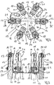
- Fig. 1 to 3 show different views of a device 10 according to the invention for the interception of optical fiber cables according to a first embodiment of the invention with a total of six intercepted at the device 10 optical fiber cables 11.
- the inventive device 10 serves to intercept the optical fiber cable 11 in an interior of a cable sleeve, not shown, wherein the Fiber optic cable 11 are introduced via insertion openings of a sealing body of the cable sleeve in the interior thereof.
- the device 10 has a mounting part 12, wherein the mounting part 12 can be fastened to the sealing body, not shown, of a cable sleeve.
- the mounting member 12 is annular in the embodiment shown and not shown fastening screws extending through introduced into the mounting part 12 holes 13, immovably fixed to the sealing body of the cable sleeve.
- the device 10 has a plurality of engaging on the mounting member 12 slide members 14.
- a total of six slide members 14 each slide member 14 of the individual support a single optical fiber cable 11 is used.
- Each of the slide parts 14 is to adjust the same to a cable diameter of each intercepted optical fiber cable within predetermined limits translationally adjustable relative to the mounting member 12, namely in the radial direction of the mounting member 12 and a sealing body of a cable sleeve to which the mounting member 12 is attached.
- each slide part 14 is assigned a guide part 15.
- Each guide member 15 is translationally adjustable relative to the corresponding slide member 14 within predetermined limits to adapt the guide members 15 to different cable diameters of the fiber optic cable 11 to be intercepted at the corresponding slide parts 14 , In the radial direction of the mounting part 12 and a non-illustrated sealing body of a cable sleeve to which the mounting member 12 is attached.
- the slide parts 14 can accordingly be displaced relative to the mounting part 12 so as to abut the same on an outer lateral surface of the optical fiber cable 11 to be intercepted and intercept the optical waveguide cables 11 on the slide parts 14.
- the guide parts 15 can be adjusted relative to the slide parts 14 in order to align the same exactly to be intercepted central elements 16 of the optical fiber cable 11, so that the central elements 16 must not be bent or bent for the purpose of interception.
- Each central element 16 of an optical waveguide cable 11 can therefore be intercepted centrally centered on the device 10 according to the invention.
- Each slide part 14 of the device 10 according to the invention has a base plate which has angled end portions 17 and 18 at two opposite ends in different directions.
- the first end portions 17 of the slide parts 14 are inserted into the U-shaped displays 19 of the mounting part 12 and slidably mounted in the same over the first end portions 17, the slide parts 14 on the mounting part 12, namely at U-shaped exhibitions 19 of the mounting part.
- the slide parts 14 can be adapted to the cable diameter of an optical waveguide cable 11 to be intercepted, in such a way that a middle section 20 of the slide parts 14 can be brought into abutment against a cable sheathing of the optical fiber cable 11 to be intercepted.
- the relative position of a slide member 14 relative to the mounting member 12 can be fixed via a locking screw, not shown, extending through a hole in the U-shaped exhibition 19 and through a slot within the first end portion 17 of the slide member 14.
- a locking screw not shown
- the slide member 14 can be moved translationally relative to the U-shaped exhibition 19 of the central part 14, in which case the position of the locking screw relative to the slot of the first end portion 17 of the slide member 14 changes.
- the set screw tightened the same fixes the relative position of the slide member 14 to the mounting part 12th
- the guide member 15 is slidably mounted in the translatory direction at the second end portion 18 of the corresponding slide member 14, in such a way that an engaging on the guide member 15 locking screw 21 is guided in a slot of the second end portion 18 of the corresponding slide member 14, wherein when dissolved locking screw 21 the same and thus the corresponding guide member 21 can be moved translationally relative to the slide member 14.
- a cable clamp 22 For the purpose of intercepting the optical waveguide cables 11, the same are fastened in the illustrated exemplary embodiment via a cable clamp 22 to the middle section 20 of a slide part 14.
- Such cable clamps are also referred to as hose clamps.
- cable clamps and cable ties for attachment and thus interception of the optical waveguide 11 can be used on the slide parts 14.
- the guide parts 15 have, as best Fig. 3 can be removed, via a recess into which a central element 16 of an optical fiber cable 11 can be inserted to intercept the same.
- this bore of the guide member 15 can be aligned exactly centered to be intercepted central element 16 of the optical fiber cable, so that the central element 16 without any bending or deflection straight into the hole of the respective management part can be introduced.
- a fixing screw 23 serves to fix the central element 16 in the bore of the guide part 15.
- Each central element 16 of an optical fiber cable 11 can be grounded individually.
- a grounding strap 24 is used, which engages with a first end on the mounting part 12 of the device 10 and with a second end on the guide part 15, in which the respective central element 16 is intercepted.
- the central elements 16 of three optical waveguide cables 11 are earthed individually via a grounding strap 24 in each case.
- a plurality of optical waveguide cables and their central elements can be individually intercepted, wherein on the one hand the slide parts 14, which respectively serve the individual interception of an optical waveguide cable 11, are individually translationally displaceable relative to the mounting part 12, and on the other hand the guide parts 15 , which serve to intercept the central elements 16 of the respective optical waveguide cable 11, are translationally adjustable relative to the respective slide part 14 in order to align them centrally with the central element to be intercepted.
- the device according to the invention can be continuously adapted to different diameters of the optical waveguide cable and thereby different positions of the central elements 16.
- the slide parts 14 of the device 10 according to the invention are arranged approximately uniformly distributed over the circumference of the annular mounting part 12.
- the slide members 14 together with the annular mounting member 12 a star-shaped interceptor, wherein, as already mentioned, on the one hand, the slide members 14 can be adjusted relative to the mounting member 12 in the radial direction continuously, and on the other hand, the guide members 15 relative to the respective slide member 14 and thus to Mounting part 12 can be adjusted continuously in the radial direction.
- tensile forces, shear forces, bending forces and torsional forces acting on the optical waveguide cables 11 and their central elements 16 can be compensated or intercepted.
- Fig. 4 shows a section of a device according to the invention 25 for the interception of optical fiber cables according to a second embodiment of the invention, together with three intercepted at the device 25 optical fiber cables 11th
- Fig. 4 differs from the embodiment of Fig. 1 to 3 only in that the slide parts 14 in the region of the second end portions 18 downwardly angled portions or tabs 26 which serve to prevent rotation of the guide members 15 at the respective second end portion 18 of a slide member 14. As a result, the ease of installation can be increased.
Landscapes
- Physics & Mathematics (AREA)
- General Physics & Mathematics (AREA)
- Optics & Photonics (AREA)
- Light Guides In General And Applications Therefor (AREA)
- Mechanical Coupling Of Light Guides (AREA)
- Apparatus For Radiation Diagnosis (AREA)
- Installation Of Indoor Wiring (AREA)
Claims (6)
- Dispositif destiné à serrer des câbles optiques dans la région d'un corps d'étanchéité d'un manchon de câble, notamment dans un espace interne délimité par le manchon de câble, comportant une partie de montage (12), dans lequel la partie de montage (12) peut être fixée au corps d'étanchéité du manchon de câble, comportant plusieurs éléments coulissants (14) s'engageant sur la partie de montage (12), dans lequel chaque partie coulissante (14) est destinée au serrage individuel d'un seul câble optique et peut être déplacée en translation à sa position par rapport à la partie de montage (12) dans des limites prédéterminées pour son adaptation à un diamètre de câble du câble optique respectif devant être serré, et comportant des parties de guidage (15) s'engageant sur les parties coulissantes (14), dans lequel chaque partie de guidage (15) est utilisée pour le serrage individuel d'un élément central du câble optique devant être serré sur la partie coulissante (14) correspondante, caractérisé en ce que chaque partie coulissante comporte une plaque de base qui présente à deux extrémités opposées des sections d'extrémité coudées dans des directions différentes, dans lequel une partie coulissante s'engage par l'intermédiaire d'une première section d'extrémité (17) sur la partie de montage (12) et peut être déplacée par l'intermédiaire de la première section d'extrémité par rapport à la partie de montage dans la direction radiale du corps d'étanchéité, et dans lequel une partie de guidage (15) s'engage sur une deuxième section d'extrémité (18) de la partie coulissante (14), laquelle partie de guidage peut être déplacée en translation sur la deuxième section d'extrémité afin d'orienter de manière centrale la partie de guidage sur l'élément central du câble optique devant être serré à sa position par rapport à la partie coulissante (14) dans la direction radiale du corps d'étanchéité dans des limites prédéterminées.
- Dispositif selon la revendication 1, caractérisé en ce que la partie de montage (12) est réalisée de manière à présenter une forme annulaire et en ce qu'elle peut être fixée de manière non coulissante au corps d'étanchéité du manchon de câble.
- Dispositif selon la revendication 1 ou 2, caractérisé en ce que le câble optique devant être serré sur la partie coulissante (14) peut de préférence être fixé par l'intermédiaire d'un serre-câble ou d'un collecteur de câbles à une section centrale (20) s'étendant entre les deux sections d'extrémité (17, 18) de la partie coulissante (14).
- Dispositif selon une ou plusieurs des revendications 1 à 3, caractérisé en ce que la position relative d'une partie coulissante (14) par rapport à la partie de montage (12) peut être fixée par l'intermédiaire d'une vis de calage s'engageant sur la première section d'extrémité (17) de la partie coulissante (14).
- Dispositif selon l'une ou plusieurs des revendications 1 à 4, caractérisé en ce que la position relative d'une partie de guidage (15) peut être fixée par rapport à la partie coulissante (14) correspondante par l'intermédiaire d'une vis de calage (21) s'engageant sur la deuxième section d'extrémité (18) de la partie coulissante.
- Dispositif selon l'une ou plusieurs des revendications 1 a 5, caractérisé en ce que l'élément central de chaque câble optique peut être mis à la terre individuellement par l'intermédiaire d'une bande de mise à la terre (24) respective qui s'engage d'une part sur la partie de montage (12) et d'autre part sur la partie de guidage (15) dans laquelle est serré l'élément central respectif.
Applications Claiming Priority (2)
| Application Number | Priority Date | Filing Date | Title |
|---|---|---|---|
| DE202006006018U DE202006006018U1 (de) | 2006-04-11 | 2006-04-11 | Vorrichtung zur Abfangung von Lichtwellenleiterkabeln |
| PCT/EP2007/001520 WO2007118545A1 (fr) | 2006-04-11 | 2007-02-22 | Dispositif de serrage de câbles optiques |
Publications (2)
| Publication Number | Publication Date |
|---|---|
| EP2005231A1 EP2005231A1 (fr) | 2008-12-24 |
| EP2005231B1 true EP2005231B1 (fr) | 2017-07-26 |
Family
ID=36746493
Family Applications (1)
| Application Number | Title | Priority Date | Filing Date |
|---|---|---|---|
| EP07722896.3A Active EP2005231B1 (fr) | 2006-04-11 | 2007-02-22 | Dispositif de serrage de câbles optiques |
Country Status (7)
| Country | Link |
|---|---|
| US (1) | US7783152B2 (fr) |
| EP (1) | EP2005231B1 (fr) |
| CN (1) | CN101421654A (fr) |
| AU (1) | AU2007237564B2 (fr) |
| BR (1) | BRPI0710590A2 (fr) |
| DE (1) | DE202006006018U1 (fr) |
| WO (1) | WO2007118545A1 (fr) |
Families Citing this family (15)
| Publication number | Priority date | Publication date | Assignee | Title |
|---|---|---|---|---|
| DE102007010863B4 (de) * | 2007-03-01 | 2009-01-08 | Adc Gmbh | Muffe für Lichtwellenleiter-Kabel |
| DE102007010855B4 (de) * | 2007-03-01 | 2009-01-08 | Adc Gmbh | Trägersystem für eine Verteilereinrichtung für Lichtwellenleiter |
| DE102007032186A1 (de) * | 2007-03-01 | 2008-12-18 | Adc Gmbh | Trägersystem zur Befestigung von Einrichtungen der Telekommunikations- und Datentechnik |
| DE102007010854B4 (de) * | 2007-03-01 | 2009-01-08 | Adc Gmbh | Konsole für eine Verteilereinrichtung für Lichtwellenleiter-Kabel |
| DE102007010853B4 (de) | 2007-03-01 | 2009-01-29 | Adc Gmbh | Verteilereinrichtung für Lichtwellenleiter |
| DE202007013984U1 (de) * | 2007-10-05 | 2007-12-06 | CCS Technology, Inc., Wilmington | Vorrichtung zur Abfangung von Lichtwellenleiterkabeln |
| DE202007014371U1 (de) * | 2007-10-12 | 2007-12-20 | CCS Technology, Inc., Wilmington | Vorrichtung zur Abfangung von Lichtwellenleiterkabeln |
| US8891930B2 (en) | 2012-08-10 | 2014-11-18 | Coring Cable Systems Llc | Fiber management frames having modular tray holder |
| US9983377B2 (en) | 2014-06-30 | 2018-05-29 | Corning Optical Communications LLC | Enclosure with combined strain relief and grounding |
| CN113348392B (zh) | 2019-01-22 | 2022-11-22 | 康普技术有限责任公司 | 用于电信机壳的电缆固定组件 |
| MX2022002923A (es) * | 2019-09-09 | 2022-07-19 | Preformed Line Products Co | Sistema de manejo de cables para un receptaculo de empalme y un receptaculo de empalme con un sistema de manejo de cables. |
| US20210165182A1 (en) * | 2019-11-29 | 2021-06-03 | Bce Inc. | Optical fiber splice closure and method of installing fiber optic cables |
| WO2021163340A1 (fr) | 2020-02-11 | 2021-08-19 | Commscope Technologies Llc | Dispositifs et agencements de fixation de câble à installation et utilisation d'espace améliorées dans des enceintes de télécommunications |
| US20220034356A1 (en) * | 2020-08-03 | 2022-02-03 | Preformed Line Products Co. | Ball peen bolt |
| FR3119686B1 (fr) * | 2021-02-05 | 2023-04-07 | Nexans | Système d’arrimage de câble au contenant d’un boîtier d’épissurage optique |
Family Cites Families (15)
| Publication number | Priority date | Publication date | Assignee | Title |
|---|---|---|---|---|
| DE3726719A1 (de) * | 1986-04-07 | 1989-02-23 | Siemens Ag | Vorrichtung zum anbringen einer mechanischen verbindung am kabelmantel eines optischen kabels |
| DE3726718A1 (de) | 1986-04-07 | 1989-02-23 | Siemens Ag | Vorrichtung zum anbringen einer mechanischen verbindung am kabelmantel eines optischen kabels |
| US4805979A (en) * | 1987-09-04 | 1989-02-21 | Minnesota Mining And Manufacturing Company | Fiber optic cable splice closure |
| US4991928A (en) * | 1990-02-20 | 1991-02-12 | Siecor Corporation | Movable clamp for fiber optic enclosures |
| GB9212624D0 (en) * | 1992-06-15 | 1992-07-29 | Raychem Sa Nv | Cable sealing device |
| DE4231181C1 (en) * | 1992-09-17 | 1993-08-26 | Siemens Ag, 8000 Muenchen, De | Cable restraint for fibre=optic cable distribution box - comprises U=shaped fixing shell fastened to rail which mounts screw for fixing cable central strain element |
| ATE187256T1 (de) * | 1994-07-21 | 1999-12-15 | Rxs Schrumpftech Garnituren | Abfangsvorrichtung für optische kabel |
| US5793921A (en) * | 1995-03-20 | 1998-08-11 | Psi Telecommunications, Inc. | Kit and method for converting a conductive cable closure to a fiber optic cable closure |
| DE69637538D1 (fr) * | 1995-09-29 | 2008-07-03 | Minnesota Mining & Mfg | |
| DE59703529D1 (de) * | 1996-03-20 | 2001-06-21 | Rxs Ges Fuer Vermoegensverwalt | Kabelmuffe |
| US5824961A (en) * | 1997-04-30 | 1998-10-20 | Lucent Technologies Inc. | Central strength member anchor for optical fiber cables |
| CN1307444C (zh) * | 2001-05-25 | 2007-03-28 | 预制管线产品公司 | 光纤电缆罩和组件 |
| DE10338848A1 (de) | 2003-08-20 | 2005-03-17 | CCS Technology, Inc., Wilmington | Abfangvorrichtung für optische Kabel, Kabelmuffe mit einer solchen Abfangvorrichtung und Verfahren zur Bereitstellung einer Abfangung für optische Kabel unter Verwendung einer solchen Abfangvorrichtung |
| DE202005009932U1 (de) * | 2005-06-22 | 2005-11-24 | CCS Technology, Inc., Wilmington | Vorrichtung zur Abfangung von in Mikroducts geführten Mikrokabeln sowie der Mikroducts |
| US7711236B2 (en) * | 2007-10-22 | 2010-05-04 | Adc Telecommunications, Inc. | Fiber optic cable clamp |
-
2006
- 2006-04-11 DE DE202006006018U patent/DE202006006018U1/de not_active Expired - Lifetime
-
2007
- 2007-02-22 EP EP07722896.3A patent/EP2005231B1/fr active Active
- 2007-02-22 WO PCT/EP2007/001520 patent/WO2007118545A1/fr not_active Ceased
- 2007-02-22 CN CNA2007800129858A patent/CN101421654A/zh active Pending
- 2007-02-22 BR BRPI0710590-8A patent/BRPI0710590A2/pt not_active IP Right Cessation
- 2007-02-22 AU AU2007237564A patent/AU2007237564B2/en not_active Ceased
-
2008
- 2008-10-10 US US12/249,480 patent/US7783152B2/en active Active
Non-Patent Citations (1)
| Title |
|---|
| None * |
Also Published As
| Publication number | Publication date |
|---|---|
| EP2005231A1 (fr) | 2008-12-24 |
| US7783152B2 (en) | 2010-08-24 |
| AU2007237564A1 (en) | 2007-10-25 |
| BRPI0710590A2 (pt) | 2011-08-16 |
| CN101421654A (zh) | 2009-04-29 |
| AU2007237564B2 (en) | 2011-09-29 |
| US20090087158A1 (en) | 2009-04-02 |
| DE202006006018U1 (de) | 2006-07-13 |
| WO2007118545A1 (fr) | 2007-10-25 |
Similar Documents
| Publication | Publication Date | Title |
|---|---|---|
| EP2005231B1 (fr) | Dispositif de serrage de câbles optiques | |
| EP1736807B1 (fr) | Dispositif destiné à la fixation de microcâbles dirigés dans des microconduits et de microconduits | |
| EP1656720B1 (fr) | Dispositif de reception pour cables optiques et manchon de cable | |
| EP0290989A2 (fr) | Prise de courant montée flottante sur une plaque de montage | |
| DE102007010854B4 (de) | Konsole für eine Verteilereinrichtung für Lichtwellenleiter-Kabel | |
| EP3699660A2 (fr) | Armoire de distribution dotée d'une entrée de tuyau vide permettant l'entrée d'une pluralité de câbles à fibre optique dans un espace intérieur d'armoire de distribution | |
| EP2198335B1 (fr) | Dispositif de retenue de câbles de guides d'ondes optiques | |
| DE19820027A1 (de) | Abfangvorrichtung für ein optisches oder LWL-Kabel | |
| EP2195694B1 (fr) | Dispositif de serrage de câbles de transmission optique | |
| EP2403084A2 (fr) | Guidage de câble et de conduite | |
| EP1904881B1 (fr) | Dispositif de distribution de fibres optiques | |
| EP4080069B1 (fr) | Système de fixation | |
| EP1744191B1 (fr) | Dispositif destiné à la récupération de câbles | |
| EP0532980B1 (fr) | Manchon à chapeau pour la réception de jonctions de câbles | |
| EP0582745A1 (fr) | Système de câblage et installation pour des arrangements équipés de guides d'ondes lumineuses | |
| EP1925061B1 (fr) | Dispositif permettant de tenir des cables | |
| DE202005012956U1 (de) | Vorrichtung zur Abfangung von Kabeln | |
| DE4104529C2 (fr) | ||
| DE9311129U1 (de) | Spleißkassette für eine Kabelgarnitur mit Lichtwellenleiterkabeln | |
| DE202005009930U1 (de) | Vorrichtung zur Abfangung von in Mikroducts geführten Mikrokabeln sowie der Mikroducts | |
| DE102021118586A1 (de) | Haltevorrichtung | |
| DE102010017054B4 (de) | Aufteilelement für einen Faserverbund und Verwendung des Aufteilelements | |
| DE10112694B4 (de) | Befestigungsklemme für ein Kabel | |
| DE202015000703U1 (de) | Befestigungskonsole zur Montage einer Lichtwellenleiterhandhabungseinrichtung an einem Befestigungsrahmen einer Lichtwellenleiterverteilereinrichtung | |
| DE2754752A1 (de) | Abfangvorrichtung und schirmverbindung fuer kabel mit wellrohrmantel |
Legal Events
| Date | Code | Title | Description |
|---|---|---|---|
| PUAI | Public reference made under article 153(3) epc to a published international application that has entered the european phase |
Free format text: ORIGINAL CODE: 0009012 |
|
| 17P | Request for examination filed |
Effective date: 20080919 |
|
| AK | Designated contracting states |
Kind code of ref document: A1 Designated state(s): AT BE BG CH CY CZ DE DK EE ES FI FR GB GR HU IE IS IT LI LT LU LV MC NL PL PT RO SE SI SK TR |
|
| 17Q | First examination report despatched |
Effective date: 20090227 |
|
| DAX | Request for extension of the european patent (deleted) | ||
| GRAP | Despatch of communication of intention to grant a patent |
Free format text: ORIGINAL CODE: EPIDOSNIGR1 |
|
| INTG | Intention to grant announced |
Effective date: 20170224 |
|
| GRAS | Grant fee paid |
Free format text: ORIGINAL CODE: EPIDOSNIGR3 |
|
| GRAA | (expected) grant |
Free format text: ORIGINAL CODE: 0009210 |
|
| AK | Designated contracting states |
Kind code of ref document: B1 Designated state(s): AT BE BG CH CY CZ DE DK EE ES FI FR GB GR HU IE IS IT LI LT LU LV MC NL PL PT RO SE SI SK TR |
|
| REG | Reference to a national code |
Ref country code: GB Ref legal event code: FG4D Free format text: NOT ENGLISH |
|
| REG | Reference to a national code |
Ref country code: CH Ref legal event code: EP |
|
| REG | Reference to a national code |
Ref country code: AT Ref legal event code: REF Ref document number: 912838 Country of ref document: AT Kind code of ref document: T Effective date: 20170815 |
|
| REG | Reference to a national code |
Ref country code: IE Ref legal event code: FG4D Free format text: LANGUAGE OF EP DOCUMENT: GERMAN |
|
| REG | Reference to a national code |
Ref country code: DE Ref legal event code: R096 Ref document number: 502007015772 Country of ref document: DE |
|
| REG | Reference to a national code |
Ref country code: NL Ref legal event code: MP Effective date: 20170726 |
|
| REG | Reference to a national code |
Ref country code: LT Ref legal event code: MG4D |
|
| PG25 | Lapsed in a contracting state [announced via postgrant information from national office to epo] |
Ref country code: LT Free format text: LAPSE BECAUSE OF FAILURE TO SUBMIT A TRANSLATION OF THE DESCRIPTION OR TO PAY THE FEE WITHIN THE PRESCRIBED TIME-LIMIT Effective date: 20170726 Ref country code: FI Free format text: LAPSE BECAUSE OF FAILURE TO SUBMIT A TRANSLATION OF THE DESCRIPTION OR TO PAY THE FEE WITHIN THE PRESCRIBED TIME-LIMIT Effective date: 20170726 Ref country code: SE Free format text: LAPSE BECAUSE OF FAILURE TO SUBMIT A TRANSLATION OF THE DESCRIPTION OR TO PAY THE FEE WITHIN THE PRESCRIBED TIME-LIMIT Effective date: 20170726 Ref country code: NL Free format text: LAPSE BECAUSE OF FAILURE TO SUBMIT A TRANSLATION OF THE DESCRIPTION OR TO PAY THE FEE WITHIN THE PRESCRIBED TIME-LIMIT Effective date: 20170726 |
|
| PG25 | Lapsed in a contracting state [announced via postgrant information from national office to epo] |
Ref country code: PL Free format text: LAPSE BECAUSE OF FAILURE TO SUBMIT A TRANSLATION OF THE DESCRIPTION OR TO PAY THE FEE WITHIN THE PRESCRIBED TIME-LIMIT Effective date: 20170726 Ref country code: LV Free format text: LAPSE BECAUSE OF FAILURE TO SUBMIT A TRANSLATION OF THE DESCRIPTION OR TO PAY THE FEE WITHIN THE PRESCRIBED TIME-LIMIT Effective date: 20170726 Ref country code: IS Free format text: LAPSE BECAUSE OF FAILURE TO SUBMIT A TRANSLATION OF THE DESCRIPTION OR TO PAY THE FEE WITHIN THE PRESCRIBED TIME-LIMIT Effective date: 20171126 Ref country code: BG Free format text: LAPSE BECAUSE OF FAILURE TO SUBMIT A TRANSLATION OF THE DESCRIPTION OR TO PAY THE FEE WITHIN THE PRESCRIBED TIME-LIMIT Effective date: 20171026 Ref country code: GR Free format text: LAPSE BECAUSE OF FAILURE TO SUBMIT A TRANSLATION OF THE DESCRIPTION OR TO PAY THE FEE WITHIN THE PRESCRIBED TIME-LIMIT Effective date: 20171027 |
|
| PG25 | Lapsed in a contracting state [announced via postgrant information from national office to epo] |
Ref country code: CZ Free format text: LAPSE BECAUSE OF FAILURE TO SUBMIT A TRANSLATION OF THE DESCRIPTION OR TO PAY THE FEE WITHIN THE PRESCRIBED TIME-LIMIT Effective date: 20170726 Ref country code: RO Free format text: LAPSE BECAUSE OF FAILURE TO SUBMIT A TRANSLATION OF THE DESCRIPTION OR TO PAY THE FEE WITHIN THE PRESCRIBED TIME-LIMIT Effective date: 20170726 Ref country code: DK Free format text: LAPSE BECAUSE OF FAILURE TO SUBMIT A TRANSLATION OF THE DESCRIPTION OR TO PAY THE FEE WITHIN THE PRESCRIBED TIME-LIMIT Effective date: 20170726 |
|
| REG | Reference to a national code |
Ref country code: DE Ref legal event code: R097 Ref document number: 502007015772 Country of ref document: DE |
|
| PG25 | Lapsed in a contracting state [announced via postgrant information from national office to epo] |
Ref country code: IT Free format text: LAPSE BECAUSE OF FAILURE TO SUBMIT A TRANSLATION OF THE DESCRIPTION OR TO PAY THE FEE WITHIN THE PRESCRIBED TIME-LIMIT Effective date: 20170726 Ref country code: SK Free format text: LAPSE BECAUSE OF FAILURE TO SUBMIT A TRANSLATION OF THE DESCRIPTION OR TO PAY THE FEE WITHIN THE PRESCRIBED TIME-LIMIT Effective date: 20170726 Ref country code: EE Free format text: LAPSE BECAUSE OF FAILURE TO SUBMIT A TRANSLATION OF THE DESCRIPTION OR TO PAY THE FEE WITHIN THE PRESCRIBED TIME-LIMIT Effective date: 20170726 |
|
| PLBE | No opposition filed within time limit |
Free format text: ORIGINAL CODE: 0009261 |
|
| STAA | Information on the status of an ep patent application or granted ep patent |
Free format text: STATUS: NO OPPOSITION FILED WITHIN TIME LIMIT |
|
| 26N | No opposition filed |
Effective date: 20180430 |
|
| PG25 | Lapsed in a contracting state [announced via postgrant information from national office to epo] |
Ref country code: SI Free format text: LAPSE BECAUSE OF FAILURE TO SUBMIT A TRANSLATION OF THE DESCRIPTION OR TO PAY THE FEE WITHIN THE PRESCRIBED TIME-LIMIT Effective date: 20170726 |
|
| PG25 | Lapsed in a contracting state [announced via postgrant information from national office to epo] |
Ref country code: MC Free format text: LAPSE BECAUSE OF FAILURE TO SUBMIT A TRANSLATION OF THE DESCRIPTION OR TO PAY THE FEE WITHIN THE PRESCRIBED TIME-LIMIT Effective date: 20170726 |
|
| REG | Reference to a national code |
Ref country code: IE Ref legal event code: MM4A |
|
| PG25 | Lapsed in a contracting state [announced via postgrant information from national office to epo] |
Ref country code: LU Free format text: LAPSE BECAUSE OF NON-PAYMENT OF DUE FEES Effective date: 20180222 |
|
| REG | Reference to a national code |
Ref country code: FR Ref legal event code: ST Effective date: 20181031 |
|
| PG25 | Lapsed in a contracting state [announced via postgrant information from national office to epo] |
Ref country code: IE Free format text: LAPSE BECAUSE OF NON-PAYMENT OF DUE FEES Effective date: 20180222 |
|
| PG25 | Lapsed in a contracting state [announced via postgrant information from national office to epo] |
Ref country code: FR Free format text: LAPSE BECAUSE OF NON-PAYMENT OF DUE FEES Effective date: 20180228 |
|
| REG | Reference to a national code |
Ref country code: AT Ref legal event code: MM01 Ref document number: 912838 Country of ref document: AT Kind code of ref document: T Effective date: 20180222 |
|
| PG25 | Lapsed in a contracting state [announced via postgrant information from national office to epo] |
Ref country code: AT Free format text: LAPSE BECAUSE OF NON-PAYMENT OF DUE FEES Effective date: 20180222 |
|
| PG25 | Lapsed in a contracting state [announced via postgrant information from national office to epo] |
Ref country code: ES Free format text: LAPSE BECAUSE OF FAILURE TO SUBMIT A TRANSLATION OF THE DESCRIPTION OR TO PAY THE FEE WITHIN THE PRESCRIBED TIME-LIMIT Effective date: 20170726 |
|
| PG25 | Lapsed in a contracting state [announced via postgrant information from national office to epo] |
Ref country code: TR Free format text: LAPSE BECAUSE OF FAILURE TO SUBMIT A TRANSLATION OF THE DESCRIPTION OR TO PAY THE FEE WITHIN THE PRESCRIBED TIME-LIMIT Effective date: 20170726 |
|
| PG25 | Lapsed in a contracting state [announced via postgrant information from national office to epo] |
Ref country code: PT Free format text: LAPSE BECAUSE OF FAILURE TO SUBMIT A TRANSLATION OF THE DESCRIPTION OR TO PAY THE FEE WITHIN THE PRESCRIBED TIME-LIMIT Effective date: 20170726 Ref country code: HU Free format text: LAPSE BECAUSE OF FAILURE TO SUBMIT A TRANSLATION OF THE DESCRIPTION OR TO PAY THE FEE WITHIN THE PRESCRIBED TIME-LIMIT; INVALID AB INITIO Effective date: 20070222 |
|
| PGFP | Annual fee paid to national office [announced via postgrant information from national office to epo] |
Ref country code: CH Payment date: 20200106 Year of fee payment: 14 |
|
| PG25 | Lapsed in a contracting state [announced via postgrant information from national office to epo] |
Ref country code: CY Free format text: LAPSE BECAUSE OF FAILURE TO SUBMIT A TRANSLATION OF THE DESCRIPTION OR TO PAY THE FEE WITHIN THE PRESCRIBED TIME-LIMIT Effective date: 20170726 |
|
| PG25 | Lapsed in a contracting state [announced via postgrant information from national office to epo] |
Ref country code: CH Free format text: LAPSE BECAUSE OF NON-PAYMENT OF DUE FEES Effective date: 20210228 Ref country code: LI Free format text: LAPSE BECAUSE OF NON-PAYMENT OF DUE FEES Effective date: 20210228 |
|
| PGFP | Annual fee paid to national office [announced via postgrant information from national office to epo] |
Ref country code: BE Payment date: 20240110 Year of fee payment: 18 |
|
| REG | Reference to a national code |
Ref country code: BE Ref legal event code: MM Effective date: 20250228 |
|
| PG25 | Lapsed in a contracting state [announced via postgrant information from national office to epo] |
Ref country code: BE Free format text: LAPSE BECAUSE OF NON-PAYMENT OF DUE FEES Effective date: 20250228 |
|
| PGFP | Annual fee paid to national office [announced via postgrant information from national office to epo] |
Ref country code: GB Payment date: 20260113 Year of fee payment: 20 |
|
| PGFP | Annual fee paid to national office [announced via postgrant information from national office to epo] |
Ref country code: DE Payment date: 20260115 Year of fee payment: 20 |