EP2005251B1 - Dispositif et procédé de commande de microstructuration d'un support d'enregistrement - Google Patents
Dispositif et procédé de commande de microstructuration d'un support d'enregistrement Download PDFInfo
- Publication number
- EP2005251B1 EP2005251B1 EP07727797A EP07727797A EP2005251B1 EP 2005251 B1 EP2005251 B1 EP 2005251B1 EP 07727797 A EP07727797 A EP 07727797A EP 07727797 A EP07727797 A EP 07727797A EP 2005251 B1 EP2005251 B1 EP 2005251B1
- Authority
- EP
- European Patent Office
- Prior art keywords
- modulator
- storage medium
- optical unit
- exposure
- written
- Prior art date
- Legal status (The legal status is an assumption and is not a legal conclusion. Google has not performed a legal analysis and makes no representation as to the accuracy of the status listed.)
- Active
Links
Images


Classifications
-
- G—PHYSICS
- G03—PHOTOGRAPHY; CINEMATOGRAPHY; ANALOGOUS TECHNIQUES USING WAVES OTHER THAN OPTICAL WAVES; ELECTROGRAPHY; HOLOGRAPHY
- G03F—PHOTOMECHANICAL PRODUCTION OF TEXTURED OR PATTERNED SURFACES, e.g. FOR PRINTING, FOR PROCESSING OF SEMICONDUCTOR DEVICES; MATERIALS THEREFOR; ORIGINALS THEREFOR; APPARATUS SPECIALLY ADAPTED THEREFOR
- G03F7/00—Photomechanical, e.g. photolithographic, production of textured or patterned surfaces, e.g. printing surfaces; Materials therefor, e.g. comprising photoresists; Apparatus specially adapted therefor
- G03F7/70—Microphotolithographic exposure; Apparatus therefor
- G03F7/70216—Mask projection systems
- G03F7/70283—Mask effects on the imaging process
- G03F7/70291—Addressable masks, e.g. spatial light modulators [SLMs], digital micro-mirror devices [DMDs] or liquid crystal display [LCD] patterning devices
-
- G—PHYSICS
- G02—OPTICS
- G02B—OPTICAL ELEMENTS, SYSTEMS OR APPARATUS
- G02B19/00—Condensers, e.g. light collectors or similar non-imaging optics
- G02B19/0004—Condensers, e.g. light collectors or similar non-imaging optics characterised by the optical means employed
- G02B19/0009—Condensers, e.g. light collectors or similar non-imaging optics characterised by the optical means employed having refractive surfaces only
- G02B19/0014—Condensers, e.g. light collectors or similar non-imaging optics characterised by the optical means employed having refractive surfaces only at least one surface having optical power
-
- G—PHYSICS
- G02—OPTICS
- G02B—OPTICAL ELEMENTS, SYSTEMS OR APPARATUS
- G02B19/00—Condensers, e.g. light collectors or similar non-imaging optics
- G02B19/0033—Condensers, e.g. light collectors or similar non-imaging optics characterised by the use
- G02B19/0047—Condensers, e.g. light collectors or similar non-imaging optics characterised by the use for use with a light source
- G02B19/0052—Condensers, e.g. light collectors or similar non-imaging optics characterised by the use for use with a light source the light source comprising a laser diode
-
- G—PHYSICS
- G02—OPTICS
- G02B—OPTICAL ELEMENTS, SYSTEMS OR APPARATUS
- G02B21/00—Microscopes
- G02B21/06—Means for illuminating specimens
- G02B21/08—Condensers
-
- G—PHYSICS
- G02—OPTICS
- G02B—OPTICAL ELEMENTS, SYSTEMS OR APPARATUS
- G02B21/00—Microscopes
- G02B21/24—Base structure
- G02B21/241—Devices for focusing
- G02B21/245—Devices for focusing using auxiliary sources, detectors
-
- G—PHYSICS
- G02—OPTICS
- G02B—OPTICAL ELEMENTS, SYSTEMS OR APPARATUS
- G02B27/00—Optical systems or apparatus not provided for by any of the groups G02B1/00 - G02B26/00, G02B30/00
- G02B27/0081—Optical systems or apparatus not provided for by any of the groups G02B1/00 - G02B26/00, G02B30/00 with means for altering, e.g. enlarging, the entrance or exit pupil
-
- G—PHYSICS
- G02—OPTICS
- G02B—OPTICAL ELEMENTS, SYSTEMS OR APPARATUS
- G02B27/00—Optical systems or apparatus not provided for by any of the groups G02B1/00 - G02B26/00, G02B30/00
- G02B27/09—Beam shaping, e.g. changing the cross-sectional area, not otherwise provided for
- G02B27/0938—Using specific optical elements
- G02B27/095—Refractive optical elements
- G02B27/0955—Lenses
-
- G—PHYSICS
- G03—PHOTOGRAPHY; CINEMATOGRAPHY; ANALOGOUS TECHNIQUES USING WAVES OTHER THAN OPTICAL WAVES; ELECTROGRAPHY; HOLOGRAPHY
- G03H—HOLOGRAPHIC PROCESSES OR APPARATUS
- G03H1/00—Holographic processes or apparatus using light, infrared or ultraviolet waves for obtaining holograms or for obtaining an image from them; Details peculiar thereto
- G03H1/04—Processes or apparatus for producing holograms
- G03H1/08—Synthesising holograms, i.e. holograms synthesized from objects or objects from holograms
- G03H1/0891—Processes or apparatus adapted to convert digital holographic data into a hologram
-
- G—PHYSICS
- G03—PHOTOGRAPHY; CINEMATOGRAPHY; ANALOGOUS TECHNIQUES USING WAVES OTHER THAN OPTICAL WAVES; ELECTROGRAPHY; HOLOGRAPHY
- G03H—HOLOGRAPHIC PROCESSES OR APPARATUS
- G03H1/00—Holographic processes or apparatus using light, infrared or ultraviolet waves for obtaining holograms or for obtaining an image from them; Details peculiar thereto
- G03H1/02—Details of features involved during the holographic process; Replication of holograms without interference recording
- G03H2001/0208—Individual components other than the hologram
- G03H2001/0224—Active addressable light modulator, i.e. Spatial Light Modulator [SLM]
-
- G—PHYSICS
- G03—PHOTOGRAPHY; CINEMATOGRAPHY; ANALOGOUS TECHNIQUES USING WAVES OTHER THAN OPTICAL WAVES; ELECTROGRAPHY; HOLOGRAPHY
- G03H—HOLOGRAPHIC PROCESSES OR APPARATUS
- G03H1/00—Holographic processes or apparatus using light, infrared or ultraviolet waves for obtaining holograms or for obtaining an image from them; Details peculiar thereto
- G03H1/04—Processes or apparatus for producing holograms
- G03H1/0476—Holographic printer
- G03H2001/048—Parallel printer, i.e. a fringe pattern is reproduced
Definitions
- the invention relates to a device and a method for controlling a device for microstructuring a storage medium.
- Microstructures of the type mentioned are known from the prior art and consist of a plurality of points and / or lines, with which a surface or one or more layers of a storage medium is changed in an optical property. In this case, a change in the reflectivity, transmission, absorption, scattering behavior, a change in the phase of the reflected light or a combination of all effects can be exploited.
- the spatial resolution may be less than 10 microns down to point or line dimensions of less than 1 micron.
- Such microstructures are used for storing information, in particular computer-generated holograms, microimages or micro-scripts can be generated with it.
- Computer-generated holograms consist of one or more layers of dot matrices or point distributions which, when illuminated with a preferably coherent light beam, lead to a reconstruction of the information encoded in the hologram.
- the point distribution can be calculated as an amplitude hologram, phase hologram or as a Kinoform Fresnell or Fourier hologram.
- these are first calculated and then written with a suitable writing device by point-wise introduction of energy into a storage medium.
- the resolution of the resulting dot matrix can, as already mentioned, be in the range below 1 ⁇ m.
- holograms with a high resolution can be written in a small space, the information of which can only be read out by illuminating with a light beam and reconstructing the diffraction image.
- the size of the holograms can be between a few 1 mm 2 and several 1 cm 2 .
- holograms can be calculated individually without much effort.
- holograms can be generated in series, which include, for example, serial numbers or production parameters.
- Such holograms can therefore be used in particular as security features or in the logistics for product tracking on packaging, credit cards, tickets or the like.
- the security features of the hologram can be read out and the authenticity and individuality of the security feature can be checked in a simple manner.
- the computer-generated holograms described above can be combined with directly visible information (microprint, microimages).
- the mentioned microimages and micro-scripts themselves can be written independently of computer-generated holograms.
- the dot distributions can also be generated as dot matrix holograms, wherein in each case individual small surface sections are generated as different diffraction structures of the dot matrix hologram.
- DOE diffractive optical element
- a laser beam in the visible wavelength range is usually meant.
- the present invention is not limited to the application of visible light. In principle, the invention can be applied to electromagnetic radiation in a wide wavelength range.
- a plurality of writing devices for writing computer-generated holograms are known from the prior art, which write in planar storage media the optical structures of the holgrams.
- WO 02/079883 WO 02/084404 .
- WO 02/084405 and WO 03/012549 pointed.
- These writing devices use a laser beam which sequentially scans every single point of the dot matrix and optionally introduces light energy into the storage medium or not.
- a plurality of reading devices are known, which are suitable for illuminating the hologram surface by means of a light beam and a suitable optical system to make the reconstruction visible or electronically representable and evaluable by means of recording means.
- a suitable optical system to make the reconstruction visible or electronically representable and evaluable by means of recording means.
- the EP 1 094 352 A2 discloses an optical writing device for imaging with a light source consisting of a plurality of arranged in a row laser diodes.
- the light emitted by this light source is directed by means of an optical system to a Grating Light Valve (GLV) from Silicon Light Machines, with which diffraction takes place for each point of the GLV.
- the GLV can also be called a line light modulator. Successive exposure creates a line by line.
- the resolution in the written image produced by the writing device is given as 2400 dpi corresponding to a dot size of about 10 ⁇ m.
- the DE 198 02 712 A1 discloses an apparatus for exposing a computer-generated hologram to a storage medium.
- the processed laser beam strikes a digital light processor (DLP), with which the 2D light field is deflected onto the storage medium.
- DLP digital light processor
- the small-area individual mirrors of the DLP generate structures in a storage medium.
- the hologram size is therefore determined by the DLP used and the scale of the image.
- a device for exposing a semiconductor structure on a wafer which for this purpose comprises a radiation source for generating a laser beam, which is passed via an optical system to a modulator.
- the modulator reflects the laser beam depending on the position of the individual modulator elements.
- the laser beam reflected by the modulator initially falls on a reduction optics, in which the phase modulation is converted into an intensity modulation.
- the laser beam reaches the wafer, which is arranged on a transport table and can thus be moved in two spatial directions with respect to the reduction optics.
- the laser, the modulator and the position of the wafer are synchronized.
- the EP 1 202 550 A1 shows a writing device with a line light modulator (GLV) and with an imaging optics.
- a polarizer is arranged, which generates a linear polarization of the beam.
- the preferred direction of the line light modulator is utilized, so that greater intensities are achieved on the writing medium. This speeds up the writing of photosensitive and heat-sensitive materials.
- the EP 1 480 441 A1 shows a construction of a writing device with a beam multiplier, which generates a plurality of individual beams from a single-mode laser beam. These then encounter a multi-channel spatial light modulator, which is modulated there individually. The individual beams reflected from the SLM are each essentially single-mode beams and the subsequent optics reproduce this plurality of individual beams onto the surface of a photosensitive workpiece.
- the method described is used, for example, for producing circuits.
- WO 01/79935 For example, a device is known with which photomasks for semiconductor elements and display devices can be produced. Likewise, semiconductor elements, displays, integrated optical elements, and electronic interconnect structures can be directly written. To generate individual points in the beam path of a laser beam, a spatial light modulator (SLM). The subsequent imaging optics then image the light modulator on the storage medium to write the structure. To an energy fluctuation between the To control individual write pulses and thus to enable a uniform writing of the structure, it is proposed to use a very fast control of a switch, which allows a shutdown of the light energy during a laser pulse.
- the WO 01/79935 assumes a mean writing power of 10-100 mW.
- the systems described above each have at least one of the following problems.
- the systems have either too low spatial resolution and accuracy of the written structuring, too low throughput or writing speed, no individually generated structures or too low writing energy, in order to be able to structure less photo- or heat-sensitive materials.
- the depth of focus ⁇ z is quadratic reciprocally decreasing.
- Due to manufacturing tolerances of the storage medium or due to inaccuracies due to the mounting of the storage medium is to be expected with a height variation of the memory material in the two-digit micrometer range. This makes an active height control necessary.
- the present invention is therefore based on the technical problem of being able to write microstructures and individual diffractive optical elements (DOEs), in particular computer-generated holograms with high speed, high precision and high writing power.
- DOEs diffractive optical elements
- Line structures with a feature size in the micrometer range (50 microns to 1 micron) or submicron range (1.0 microns to 0.01 microns) can write.
- Another technical problem is to provide a system that can write high-speed dot / line structures (typically 100 MP / s) or higher.
- Another technical problem is to provide a system with which large-area microstructures in the range of 1 mm 2 to 1 m 2 , typically 1 cm 2 can be written.
- Another technical problem is to provide a system that can write microstructures into a less viscous material (eg, thin aluminum layers, metals, polymers, rare earths).
- a less viscous material eg, thin aluminum layers, metals, polymers, rare earths.
- the reduction optics are diffraction-limited and the reduction optics produce, starting from the surface of the individual modulator elements, an area reduction of at least 25.
- the individual modulator elements are each irradiated with a plane wave or an approximately plane wave, so that an optimal result, ie very small diameters of the individual reduced points, is achieved by the diffraction-limited reduction optics.
- the Raileigh criterion can be used, which states that over each modulator element the deviation from the plane wave is not greater than ⁇ / 4, with ⁇ the wavelength of the light.
- a modulator operating in parallel for example a line light modulator
- a plurality of individual dots or lines of an individual structure may be written in the storage medium.
- the diffraction-limited reduction optics and the associated large reduction make it possible to write very small structures with high writing power. This enables fast and massively parallel writing of microstructures in materials that could not previously be described.
- high energy densities can be controlled with the modulator, which would otherwise destroy the modulator itself.
- DOE in particular computer-generated holograms
- the writing speed can reach up to, for example, 100 MP / sec.
- Another advantage is that a high positioning accuracy of the diffractive exposure points can be achieved.
- the microstructuring can be written by a suitable control of the modulator with different intensity, so for example with different gray levels.
- diffraction limit is described according to DIN ISO 10110-5 as follows.
- a measure of the imaging quality of a system is the "Strehlian definition brightness” or the “Strehl intensity ratio", ie the ratio of the intensity in the center of the point image to that Intensity defined for the aberration-free optical system. This tells us how much light is combined in comparison to the theoretically possible light in the diffraction disk, also called Airy disk, and how much light is outside.
- a Strehl value of 1 corresponding to 100% means that the light present inside the diffraction disk reaches the theoretically maximum value. Such a system would be free from aberrations.
- Optics with a Strehl value better than 0.8 are considered to be diffraction-limited according to this standard.
- the reduction in area of the reduction optics be between 25 and 1000, preferably between 50 and 1000, in particular 250 is.
- particularly small and intense light structures or light points can be generated line by line or areal, which are able to modify even less photosensitive materials sufficiently to produce a microstructure.
- Examples of such materials are thin aluminum layers, metals, polymers, rare earths in which by pointwise introduction of energy restructuring, displacement processes, condensation processes, ablation or evaporation processes are triggered.
- the reduction optics reduce the radiation intensity diffracted by each modulator element to a size of less than 10 ⁇ m diameter, in particular less than 1 ⁇ m diameter.
- the radiation source is designed as a laser.
- this embodiment of the light source does not constitute a limitation of the invention.
- the laser is the preferred means for generating an at least partially coherent beam of electromagnetic radiation.
- a pulsed laser is used whose pulse has a higher energy density than the laser beam of a continuous wave laser.
- a typical example of a pulsed laser can be characterized as having pulse durations in the Nanosecond range and that the energy of a pulse is in the range of 100 microjoules. This means at 1024 points of a line light modulator one energy per pulse and modulator element of about 0.1 microjoule. As a result, a sufficient energy density for material structuring is given, which depends only to a small extent on the thermal conductivity of the material.
- the type of generation of the microstructures is therefore optimally realized when high-energy laser pulses in the visible or adjacent wavelength ranges are used to microstructure the storage medium. This results in a wider range of materials to be used.
- the use of a cw laser is possible in principle, but not so advantageous because of the lower energy density.
- the laser generates a monomode laser beam, so that on the one hand the coherence properties of the light beam are optimal and on the other hand there is a regular intensity distribution of the laser beam transversely to the propagation direction.
- the laser may also be sufficient if the laser generates a multimode laser beam with partial coherence. Even if the intensity distribution of the laser beam produced is not optimal and may need to be compensated, it is sufficient if the beam directed onto the modulator has a spatial coherence extending over at least some modulator elements. It is therefore not important that all modulator elements are irradiated with mutually coherent light.
- An example of a pulsed laser system is a diode-pumped solid-state laser in the visible spectral range.
- An essential element for generating an intensity-modulated beam is the already mentioned modulator.
- the individual modulator elements can be controlled electronically in order to adopt at least one of two possible settings.
- the modulator is continuously switchable and acts as a local phase modulator.
- One or two-dimensional modulators can be used. The latter, however, have the disadvantage that a two-dimensional illumination of the surface of the modulator is required, which is more difficult than a one-dimensional illumination.
- Another disadvantage is that interference effects in two-dimensional exposure are more pronounced in certain constructions of the storage media. Thus, it represents a simplification of the system when a one-line design is chosen and homogenization of the beam intensity is only necessary in one dimension.
- a single-line, consisting of separately switchable modulator elements line light modulator has been found. If this line light modulator is sequentially controlled in such a way that a different intensity distribution is generated after each new setting, then different microstructuring lines can be successively written into the storage medium. This results in a surface or area with a microstructure, which are designed individually can. Because for each write operation, the light modulator must be redirected, so it can be controlled differently for each write.
- the line structure of the surface light modulator is preferably imaged perpendicular to the scanning movement on the storage medium in order to achieve the widest possible width of the written strip.
- a modified embodiment provides a non-orthogonal orientation. As a result, a finer resolution can be achieved with a reduced writing width.
- a single-line light modulator is a Grating Light Valve (GLV) from Silicon Light Machines, CA, USA.
- This line light modulator has separately switchable diffraction gratings.
- Each modulator element has a plurality of mutually parallel and arranged in a plane bands, of which, for example, every second band can be electrostatically adjusted out of the plane.
- the modulator element acts either as a mirror or as a small diffraction grating, which diffracts the light intensity in a direction deviating from the direction of reflection.
- each modulator element can deflect the incident light to different extents in the direction of reflection or diffraction.
- the already mentioned beam-shaping optical system serves to illuminate the single-line or two-dimensional light modulator. It is desirable that the illumination of the modulator is as uniform as possible, so that a homogeneous intensity distribution is achieved, which lead to the same write intensities on the storage medium with the same activation of the individual modulator elements. In general terms, therefore, the beam-shaping optical system should generate a beam profile adapted to the surface of the modulator from the beam profile generated by the radiation source.
- the beam shaping optical unit has a Powell lens.
- a Powell lens is out of the US 4,826,299 For example, from a Gaussian intensity distribution, an intensity distribution which is substantially similar to a rectangular shape is generated.
- a beam-shaping optical system is used, the function of which is to generate from the beam profile of the light source or of the laser a beam profile adapted to the geometry of the line light modulator.
- the reduction optics is a microscope objective.
- a conventional technique can be used to focus and reduce the intensity distribution generated by the modulator on the storage medium.
- the reduction optics preferably have at least two objectives with different focal lengths and / or numerical apertures.
- a removable microscope objective can be used, so that the lenses used in light microscopes are used without great expense of a special development can.
- the focal length or numerical aperture By changing the focal length or numerical aperture, the size of the individual structures or points can be changed in a simple manner. When using a change optics then easy switching between different structure sizes and pitch is possible. One can also speak of a rapid change in the grid size. In this case, by changing the focal length of the optics, the grid dimension, that is to say the distance of the individual points from each other, is changed, while the change of the numerical aperture changes the point size. Therefore, when the lens is changed, the pitch and the dot size do not change in the same way.
- the reduction optics comprise a spatial frequency filter.
- the function of the spatial frequency filter is to convert a phase modulation into an intensity modulation.
- the spatial frequency filter is preferably combined with the reduction optics, wherein the required aperture is disposed within the reduction optics.
- the reduction optics with combined spatial frequency filter thus represents nothing else than to arrange a filter in the form of a pinhole in the Fourier plane in order to convert the phase modulation of the modulator, in particular of the line light modulator, into an intensity modulation in the write beam.
- the above-mentioned transport device is provided for the transport of the storage medium relative to the reduction optics. It is preferred that the transport device is designed as a transport table and preferably uniaxial, in particular biaxial is adjustable. Thus, the storage medium can be moved in any direction transverse to the propagation direction of the focused light beam. Likewise, the transport device may also be designed as a conveyor belt.
- a movement of the storage medium relative to the write head in two directions makes it possible to write several tracks of a microstructure next to each other and thus to be able to process larger areas.
- the transport table preferably has a high accuracy in the position determination, but not in the movement itself. By massively parallel exposure, the speed of movement can be reduced accordingly, because it does not depend on high speeds when moving the storage medium.
- a transport table is used with a rolling drive, in particular with a position feedback system.
- the exact position detection is used to trigger the writing process itself, so the transport table is by its movement and its exact positioning the means controlling the synchronization of the writing process.
- the material movement triggers the laser system and causes the controller to provide the modulator with the next exposure information.
- the accuracy is increased by the synchronization, especially in large-area exposures.
- a movable optical element in particular a beam splitter or mirror is provided in the beam path in front of the reduction optics for moving the reduced intensity pattern on the storage medium.
- an actuator for. B. to the movement of the beam splitter or the mirror, the exposure line generated by the modulator or the exposure section can be moved relative to the storage medium.
- the detection of an edge or mark can therefore be detected by means of a camera.
- detection of an edge during the transport movement for example by means of a photodetector arrangement, may be advantageous and thus preferred.
- the exposure to a predefined position in the material of the storage medium takes place.
- This sets a detection of the predefined position, eg. As an embossed mark or track, for which purpose again the already mentioned camera system or the photodetector arrangement can be used in an advantageous manner.
- the device therefore preferably has a camera system for controlling the microstructuring, which is integrated into the beam path in such a way that it can detect the surface of the storage medium by means of a separate illumination and observe and render its structuring or marking for evaluation.
- a beam splitter is provided in a preferred manner by which on the one hand the beam deflected by the modulator and on the other hand the light is conducted from or into the optical branch of the camera system.
- the camera system may be provided for controlling a predetermined orientation or alignment relative to a predetermined or already written microstructuring or marking. This can be used in particular for an improved sequencing of the exposure strips of several write operations.
- a controller which synchronizes the laser, the modulator and the transport table.
- the type of synchronization by the movement of the transport table has already been mentioned above, wherein the transport table generates a trigger signal with its exact position determination, which is received by the controller and further processed.
- the controller then generates control signals for the activation of the laser and the modulator at appropriate time intervals according to the speed of the transport table and sends to this.
- the control system can also be used for fast data processing and transmission of the data to the modulator or the light modulator.
- the control is preferably based on two coupled computers (control computer and data computer).
- the control computer provides the user interface and controls all non-time-critical processes. This includes all initialization tasks, calibration routines, diagnostic tools, etc.
- the data processor is responsible for providing the data to be processed. Both computers communicate with each other via a connection. Time-critical functions such as the triggering of the laser and the control of the modulator are taken over by a suitable processor card.
- the position signal of the transport table in particular of the XY linear table is preferably used. Depending on the position signal, the processes are controlled during the exposure.
- the respective microstructures can be generated successively by the modulator or light modulator.
- the points of structuring are written into the storage medium line by line at predetermined intervals. It is mainly on the same distances between the individual lines to achieve a uniform arrangement of the dots or lines in a given grid.
- the transport table is moved continuously and the master trigger T 0 are generated by the movement of the transport table by a predetermined distance. In this way, the transport table is moved continuously and not driven to individual movement steps.
- the above-mentioned camera system can be used in a preferred manner, the above-mentioned camera system to the position of the To measure first structuring track, so to capture the edge of the first structuring track.
- a continuous tracking of the device can take place.
- a photodetector arrangement can also be used.
- the transport table can be moved transversely to the writing direction so that the second structuring track is written directly adjacent to the edge of the first structuring track.
- the camera system can also be used to enable an alignment, that is, an assignment to already pre-structured materials, in particular to pre-structures produced by printing, embossing, partial metallizations and already existing holograms.
- the abovementioned adjustable optical element for example in the form of the beam splitter or mirror.
- the modulator can be moved or adjusted by means of a piezo drive.
- a storage medium can be microstructured by means of a device described above, with an optically modifiable layer, wherein the Layer is microstructured in a predetermined range, wherein the dimension of the microstructured region is at least in one direction at least 10 mm. Preferably, the dimension is at least 50 mm.
- the resolution of the microstructuring may be in the micrometer range and also in the sub-micron range.
- the microstructured area may be inscribed in the form of a strip having a length which is several times the width of the strip.
- the length ratio of the side edges of the microstructured area is changed so that, for example, a strip with a plurality of microstructured information can be stored on a security document, which strip can be read out and checked for authenticity checking.
- the length may preferably correspond to at least three times the width, preferably five times the width, in particular ten times the width.
- the microstructured area may have at least two different information contents, wherein preferably at least one information content is a computer-generated hologram.
- the information content may be a dot matrix hologram a microimage or a microform or a microcode.
- the section of the surface of the storage medium with at least one sampling point can be detected for both directions of movement of the writing process.
- at least two sampling points can be used to detect not only a distance but also a tilt of the storage medium relative to the imaging optics.
- the above-described autofocusing systems and methods for adjusting the distance of the storage medium from the imaging optics enable a sufficient tracking of the distance between the storage medium and the imaging optics, which is required due to the strong focus and the associated very short expansion of the focus along the propagation direction.
- the exposure strategy does not depend on the exact configuration of the device described above, but rather relates to all exposure processes in which microstructures are introduced line by line or area by area into a storage medium.
- the method thus serves to correct so-called proximity effects that occur during the writing process.
- this control system for correcting the proximity effects during runtime together with an algorithm consisting of a splitting of the line profile into a proportional component and a differential component is applied.
- the correction depth can be set.
- a special pulse strategy is used as a degree of freedom in the material structuring, which is preferably electronically adjustable, in particular depending on whether the exposure line is oriented orthogonally or obliquely to the direction of movement.
- the degree of structuring of individual exposure points in a screened pattern should be independent of the structuring or exposure of the surroundings.
- the effect of the different formation of the memory points can be compensated by preprocessing the data to be written.
- This also exposure strategy is to write separate pixels that have no direct neighbors.
- Fig. 1 shows the structure of the optical components of a device for microstructuring a storage medium
- a laser 4 serves as a radiation source for generating an at least partially coherent light beam 14.
- a light modulator 6 is arranged in the form of a line light modulator in the beam path, which has a plurality of individually switchable modulator elements.
- a beam-shaping optical system which is designated overall by the reference numeral 8, serves to illuminate the modulator 6.
- a reduction optics which is designated overall by the reference numeral 10, serves to reduce the intensity distribution emitted by the modulator 6.
- a transport table 12 is provided to move the storage medium 2 relative to the reduction optics 10.
- the reduction optics 10 are diffraction-limited and the reduction optics 10, starting from the surface of the individual modulator elements, produce an area reduction of at least 25, preferably of at least 50.
- the range of favorable reduction factors is in the range between 50 and 1000, in particular at 250.
- the reduction optics 10 thus reduces the radiation intensity diffracted by each modulator element to a size of less than 10 ⁇ m diameter, in particular less than 1 ⁇ m diameter.
- the structure sizes that can be achieved on the surface of the storage medium are thus to be classified in the micrometer range down to the submicrometer range.
- Such small structuring in describable by the device according to the invention surface sizes up to 1 m 2 lead to a variety of new applications.
- the laser 4 is designed as a pulsed diode-pumped solid-state laser in the visible spectral range and generates a monomode laser beam 14.
- the modulator 6 is a single-line, consisting of separately switchable modulator elements light modulator, which is also known as Grating Light Valve (GLV).
- the individual modulator elements each consist of a plurality of individual strips which can be alternately adjusted by electronic control out of their planar arrangement. By an appropriate control, the adjustable strips in the plane of the non-adjustable strips can be arranged so that a reflective surface is formed. On the other hand, if the strips are displaced, a modulator with a radiation characteristic deviating from the reflecting surface results. As a result, the emission characteristic of the individual modulator elements can be changed specifically and thus Set a characteristic line pattern across the plurality of modulator elements.
- a grating light valve has 1000 or more modulator elements. The dimension of such a line light modulator can typically be 30 mm ⁇ 25 ⁇ m, with the individual modulator elements having dimensions of approximately 25 ⁇ m in length.
- the beam-shaping optical system 8 generates from the round beam profile of the laser beam 14 with Gaussian radial intensity distribution a beam profile adapted to the area of the single-line light modulator.
- the beam-shaping optical system 8 initially two lenses 16 and 18, which expand the laser beam 14 and which are arranged at a distance of the sum of the two focal lengths to each other.
- the focal length of the lens 16 is smaller than the focal length of the lens 18.
- the laser beam therefore has a larger diameter than at the output of the laser 4th
- the beam path then has two cylindrical lenses 20 and 22, which generate an elliptical intensity distribution in the section 14b of the beam path from the expanded rotationally symmetrical intensity distribution of the laser beam 14.
- the beam-shaping optical system 8 then has a Powell lens 24, which generates from the elliptical intensity distribution an approximately rectangular intensity distribution, also referred to as flat-top.
- the Powell lens is known per se from the prior art, as already indicated in the general description. In section 14c of the beam path, therefore, the laser beam has a substantially uniform intensity distribution along the in Fig. 1 illustrated vertical direction.
- a collimating lens 26 generates from the diverging beam leaving the Powell lens 24 a parallel beam focused by the subsequent cylindrical condenser lens 28.
- a mirror 30 directs the focused beam onto the line light modulator 6.
- the modulator elements of the line light modulator 6 are arranged essentially in the focal plane of the converging lens 28.
- each modulator element is illuminated with a plane wave whose deviation from the plane wave does not exceed a maximum value of ⁇ / 4.
- adjacent pixels are irradiated with light whose plane wave properties do not differ from each other by more than ⁇ / 4.
- the beam-shaping optical system 8 is preferably designed to be diffraction-limited as a whole.
- the reduction optics 10 is arranged in the beam path behind the line light modulator 6.
- a collimation optics consisting of two lenses 32 and 34 is provided, which generates in the section 14d parallel beams in the section 14e from the individual beams radiated by the nearly point-shaped modulator elements. These parallel beams are then transmitted from a lens 36 to the surface of the lens Storage medium 2 focused.
- the focused beam can then also be referred to as a writing beam because it introduces the writing energy required for microstructuring into the storage medium 2.
- the reduction optics 10 can have at least two different objectives with different focal lengths and / or numerical aperture in order to achieve a fast switching between differently sized spot sizes when generating the microstructuring.
- the objectives 36 are preferably designed as microscope objectives.
- a pinhole 37 is arranged as a further beam-shaping element.
- the pinhole 37 realizes a spatial frequency filter. Due to the collimation optics of the lenses 32 and 34, the image of the modulator elements of the modulator 6 is Fourier-transformed into the Fourier plane in the region of the perforated plate 37. Higher diffraction orders that arise in the Fourier plane are blocked by the perforated diaphragm 34, so that largely only the light of the zeroth diffraction order is focused by the objective 36.
- An alternative construction can be realized by blocking the zeroth order instead of the first order and by transmitting one of the first orders. As a result, a higher contrast can be achieved, but at the expense of the intensity of the writing beam.
- the aperture plate 37 preferably has a rectangular hole, since the beam generated by the line light modulator 6 assumes a substantially rectangular shape, especially in the Fourier plane. In contrast, it is also possible to use an elliptical or round hole shape.
- the transport table 12 shown below the storage medium 2 is biaxially adjustable and can therefore be moved in a plane transverse to the beam propagation of the focused beam below the microscope objective 36.
- the transport table 12 may move the storage medium 2 toward the reduction optics 10 to allow for height adjustment. This degree of freedom is advantageous for carrying out an autofocusing mentioned below, in order to keep the storage medium as accurately as possible in the focus of the reduction optics 10.
- a dichroic beam splitter 38 is arranged, which can be moved by means of an actuator, not shown, along the propagation direction of the beam 14 e.
- the focused line of exposure points transversely to the movement of the storage medium 2, which is shown by the arrow A, adjusted and adjusted.
- Fig. 2 shows the optical structure for monitoring and controlling the writing process, in particular also for the alignment of the structures to be exposed to existing structures on the storage medium 2.
- a camera system 40 among other things for a control of the microstructuring, and on the other an autofocusing system 42 provided.
- Both systems 40 and 42 begin at the previously described dichroic beam splitter 38.
- another, preferably likewise dichroic, beam splitter 44 is provided, which divides the two beam paths for the camera system 40 on the one hand and the autofocusing system 42 on the other hand.
- the camera system initially has a lighting device in the form of a light source 46, which is designed as a diode lamp (LED) or as a halogen lamp.
- a lighting device in the form of a light source 46, which is designed as a diode lamp (LED) or as a halogen lamp.
- An adjustable aperture 48 controls the intensity of the light emitted to the surface of the storage medium 2 amount of light.
- the beam splitter 44 the light beam is directed downward in the direction of the storage medium 2, wherein the light beam is focused by means of the lens 36.
- Fig. 1 which shows the running in the direction of the camera system 40 and the autofocus system 42 jet approach 39.
- the light reflected from the surface of the storage medium 2 passes through the lens 36, the beam splitters 38 and 44 again in the opposite direction and strikes a, preferably 50:50, beam splitter 50.
- the light beam (in FIG Fig. 2 shown offset) through a lens 52 and a polarizer 54 and strikes a camera 56th
- the arrows B indicate that the camera 56 can be moved transversely to the propagation direction of the beam. This freedom of movement serves to be able to observe a sufficiently large area of the surface of the storage medium 2 with a sufficiently large resolution. If for example, the line light modulator 6 has about 1000 modulator elements and if the observation of the imaged dots on the surface of the storage medium or the inscribed microstructure is to take place with a resolution of 4 pixels, then chips with a quantity of 4000 pixels in one direction are required. which are only available as custom-made products. On the other hand, if conventional chips are used, then their quantity of pixels is insufficient, so that the lack of resolution can be compensated by means of the described movement transversely to the propagation of light. The movement of the camera 56 thus scans the area of the storage medium 2 to be observed.
- the camera branch 40 described above can fulfill three tasks.
- the camera branch 40 can be used for the preliminary examination of the storage medium 2 to be exposed, can be used for a microscopic examination of the structured region of the storage medium 2 or can be used to calibrate the modulator 6, for example the line light modulator.
- the polarizer 54 arranged in front of the camera 56 can serve a stepless intensity attenuation during the calibration of the line light modulator.
- the camera branch 40 can advantageously be used for fast but also precise adjustment of the overall system.
- the positioning of the laser diodes described below or Laser diodes are used for height control relative to the write laser or the exposure line.
- FIG. 10 illustrates an autofocusing system 42 for adjusting the removal of the storage medium 2 from the reduction optics 10.
- a first laser diode 60 is provided, whose light is collimated by means of a lens 62 and directed by two preferably 50:50 beam splitters 64 and 66 and by the dichroic beam splitter 38 and by the lens 36 to the storage medium 2.
- the reflected light then runs in the opposite direction and a portion of the reflected light is passed through the beam splitter 66 in the direction of a 4-quadrant detector 68, wherein in the further beam path, a focusing lens 70 and another preferably 50:50 beam splitter 72 are provided.
- the coplanar plate 74 an astigmatism is generated, so that the signal generated by the 4-quadrant detector has directional information regarding the defocusing of the light beam on the surface of the storage medium.
- a distance deviation of the storage medium 2 from the reduction optics, ie from the objective 36 can be determined and the corresponding signal can be used to control the distance, that is to say for autofocusing.
- Parallel to the first laser diode 60 and the 4-quadrant detector 68 are a second laser diode 76 with a further lens 78 and a further 4-quadrant detector 80 provided.
- the light of the second laser diode 76 is directed via the beam splitter 64 in the same way as the light of the first laser diode 60 to the surface of the storage medium 2 and reflected from there.
- the reflected light is then directed onto the 4-quadrant detector 80 through the beam splitter 72, which then acts as a coplanar plate and provided with astigmatism. There, a distance deviation of the storage medium 2 from the lens 36 can then be determined based on the direction information of the defocusing.
- Fig. 2 is still shown at the bottom, that instead of the dichroic beam splitter 38, a mirror can be used, which then directs the light modulated by the line light modulator 6 on the camera system 40 and thus allows direct observation of the operation of the Zeilenlichtmodulators.
- the beam splitter 38 and mirror 82 are jointly adjustable along the direction shown by the arrow C, so that a switch between the two modes is easily possible.
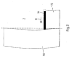
- Fig. 3 shows a schematic representation of the description of the storage medium 2 with two side by side lying strips 90 and 92 with microstructures that are to form, for example, a coherent computer-generated hologram.
- the edge of the strip 90 deviates from the straight line shown in dashed lines, wherein the size of the deviation is exaggerated.
- the strip 92 to be rewritten should be written as close as possible to the first strip.
- the right edge of the strip 90 observed and, for example, the beam splitter 38 adjusted so that the currently to be written line 94 is adjusted by a determined by the evaluation of the camera system 40 distance to the left according to the arrow D.
- the height control system preferably operates with several sampling points, in particular with two sampling points.
- a dichroic beam splitter 38 separates the exposure path from the camera system 40 and the autofocus system 42 of the optical assembly. See again Fig. 2 ,
- the autofocus for locating and holding the focus of the write beam in the area of the storage layer of the storage medium 2 consists of an autonomous system based on the astigmatism method.
- an optic is used which has different focal lengths in two mutually perpendicular directions, generally at right angles to the propagation direction of the light.
- focal planes are achieved for the two directions at different distances to the optics, which cause a distortion of the beam diameter in the other direction. Only in the region of half the distance between the two focal planes of the beam cross-section is round.
- a four-quadrant detector can then be determined how much and in which direction the recorded beam cross-section deviates from the round shape. From the deviation, a reset signal can then be generated in order to set a uniform illumination of the four-quadrant detector.
- the detection point depending on the direction of movement of the storage medium 2 relative to the writing beam, must be either on the left or on the right side of the exposure area. Because only in a non-structured, so unexposed area of the storage medium 2, a meaningful evaluation of the focus error signal is possible.
- the autofocus point is intended to be determined in anticipation of the writing process in order to be able to subsequently correct a change in the height position of the surface of the storage medium 2.
- the two laser diodes 60 and 76 are each arranged so that the two illumination points are arranged on the left and right of the focus line of the focused write beam on the surface of the storage medium 2.
- the two laser diodes 60 and 76 are mechanically and / or electrically adjustable in their position.
- the two independent autofocus systems are also arranged in a space-saving nested arrangement and share several optical components.
- the branches with the four-quadrant detectors 68 and 80 share the focus lens 70.
- further light sources may be provided to allow further illumination points for further autofocusing systems.
- each light source also one in each case Four-quadrant detector for measuring the deviation of the illumination point from the specified position.
- two or three illumination points can be arranged on each side of the focused write beam on the surface of the storage medium 2. The principle described here is therefore not limited to two light sources.
- the multi-sample spotlight system described above may also be referred to as a multi-point astigmatism height control system.
- different height control signals are then evaluated or the system changes the position of the scanning beam by adjusting the position of the light sources or arranged in the beam path optical means such as beam splitters or mirrors.
- the operating point is determined.
- the operating point determination can be automated, in particular in the case of continuous exposures, by analyzing the diffraction efficiency of a written test structure in temporal and spatial proximity by means of preferably a photodetector or a camera with changing adjustment of the operating point. About the place or time can then be closed on the operating point which achieved the best, but not necessarily the highest, diffraction efficiency.
- additional information can be obtained by evaluating higher diffraction orders.
- the operating point preferably automatically, be carried out by the evaluation of a contrast function of the exposed structure.
- a tilting correction of the storage medium during the transit time can take place by means of an actuator which tilts the diffraction grating 6 in the corresponding direction.
- an electronic offset correction may be provided.
- the offset correction consists in an adjustable additional delay time and / or a local pre-trigger of the laser. This compensates for the time that elapses between measuring the height position or the tilt and the writing time in which the storage medium is moved between the measuring position and the writing position. Further, the tilt is also realized by an additional adjustable delay - but here linearly increasing, whereas it is fixed in the offset compensation.
- the height control is based on the astigmatism principle, as it is used in CD or DVD drives. Based on the orientation of the back-reflected beam imaged by the astigmatism on a four-quadrant detector, the extent and orientation of the defocusing can be detected. This information is used to control an actuator, which follows the sample or the optical system according to the height profile of the storage material.
- the method for operating point determination is based on the production of an exposure wedge.
- This is on the Fig. 4 ,
- a region of the material is structured in which the intensity along one axis and the exposure height along the other axis is changed continuously.
- a value range of 16 different gray levels is preferably used.
- the height is varied over the range of the S-curve (about 20 ⁇ m) previously established when adjusting the S-curve.
- a microscopic analysis of the exposed area results in a wedge, see Fig. 4 , It is assumed there the optimum exposure height, where it comes to the structuring at the lowest intensity.
- the focus error signal (FFS) is used as a reference for an optimal exposure.
- the FFS voltage is thus the operating point of the height control.
- the exposure of the wedge should be done at normal exposure speed in order to increase the significance for the later large-area exposure.
- the exposure of the gray value wedge and the determination of the operating point are as follows:
- an area for the gray value wedge is selected by means of the microscope function in the camera branch of the device. This is done by zeroing a position counter in the control electronics.
- the exposure pattern of the gray value wedge (16 gray values) is loaded.
- the transport table is reset by a defined position to start up for the exposure process.
- the height control module is placed in the gray value wedge mode. This causes the values of the S-curve to be stored in a memory triggered by the laser pulse.
- the memory can either be preferred in the height control module or in the control electronics.
- the exposure of the gray value wedge is preferably carried out over 16 gray value or intensity levels and 128 height levels, wherein the stated numerical values are to be understood by way of example and are merely preferred.
- the drive voltage of the piezo actuator of the height adjustment of the microscope objective in the previously defined areas is changed.
- the range restriction occurs when adjusting the height of the S-curve by means of user intervention. Simultaneously with the exposure and the Changing the piezo voltage, the value of the S-curve is determined and stored.
- the microscope mode of the device is activated.
- the tip of the exposure wedge is moved to the center of the camera image by the process of the linear stage.
- the current position of the transport table is read from the control electronics.
- the stored S-curve data is also read out. On the basis of the current position in the read-out S-curve data, that S-curve value can be read in which there is an optimal exposure. This value is the operating point of the height control.
- the system looks into the future or the system can compensate the reaction time of the electronics and the actuator.
- the are Detection points in the middle of the exposure line however, any other position can be selected, if this is advantageous.
- each detected a detection point on each side of the illumination line in a direction of movement no tilting of the storage material along the exposure line and thus compensated.
- the storage material and the focus area (depth of field) of the exposure beam being parallel. Only across the orientation of the exposure line, a height control can be done.
- the structure of the two-point height control is in Fig. 6 and is similar to the one-level control described above.
- two detection points or sampling points for each direction of movement are used instead of a detection point or sampling point.
- the advantage of this system is that independent altitude controls can be used for each detection point.
- a detection point, z. B. the in Fig. 6 each upper detection point can be integrated in a closed height control loop with the piezoelectric actuator on the microscope objective, wherein the other detection point, for. B. the in Fig. 6 each lower detection point can in a control loop with a tilting mechanism, z. B. at the attachment of the Zeilenandermodulators, can act.
- ordinary linear standard controllers for example a PID controller, can be used.
- the tilting component can be separated from the z-component by a coordinate transformation and then given to the respective actuator control loops.
- FIG. 7 Another preferred alternative to the previous systems and methods for detecting the position of the storage layer with one or two fixed detection points is a system which operates with a scanning detection point and thus realizes a scanning height control.
- the principle of scanning height control is in Fig. 7 shown.
- a detection point is scanned along the exposure line or perpendicular to the direction of movement, resulting in, for example, a substantially sinusoidal waveform.
- the material is thereby exposed areally and simultaneously scanned.
- the detection point obtains information about the height profile of the storage material before the exposure line via the astigmatism method described above.
- This information is composed of the error signal including the voltage of the piezo actuator of the microscope objective. Combining the two information with the control or current position of the detection point, we obtain a height profile.
- the aim of a regulation is then the integral of the focus error to minimize by the scheme on the one hand adjusts the piezoelectric actuator of the microscope objective and on the other hand adjusts the actuator for the tilting of the exposure line relative to the storage material.
- the advantage of this solution is that a height profile can be recorded over the entire writing area or at least part of the writing area. This makes an ideal adjustment of the height and tilt possible. Errors due to dirt particles in the detection point can be detected as such and eliminated. In addition, a curvature of the memory material can be taken into account, which is not recognized in a two-point detection. Moreover, a height profile of the storage medium for quality assurance tasks can be created.
- a further preferred embodiment of the height control consists in a wavefront height control, which can be used for height control or detection of the storage surface, a system that works similar to a wavefront sensor, as in Fig. 8 is shown.
- a collimated laser beam 100 after deflection by means of a beam splitter 101, strikes a storage medium 102.
- the back-reflected wave is directed via an intermediate focus, which is produced by the pair of lenses 104 and 106, to a one-dimensional lens array 108, which preferably has cylindrical lenses 110.
- the position of the focus is dependent on the angle of the incoming beam 112 and thus on the tilt of the surface of the storage medium 102.
- the displacement of each focus of the individual lenses 110 may be used to detect the position and orientation of the surface of the storage medium 102. Moreover, this method offers a possibility of obtaining areal information about the surface of the storage medium 102.
- a two-dimensional lens array with a two-dimensional detector preferably a camera chip
- the actuators for height and tilt of the storage medium relative to the objective for example the objective 36 in FIG Fig. 1 , anticipate.
- a simple wavefront sensor with the in Fig. 9 be realized construction shown.
- a plurality of sample beams 120 at different angles to the schematically illustrated microscope objective 122, for example, the lens 36 in Fig. 1 may correspond, and the storage medium 102 is directed.
- each sample beam 120 undergoes its own offset, each with small arrows in Fig. 9 is shown above.
- a planar sensor (camera chip) can determine the offset with respect to a reference position by means of the center of gravity calculation of the measured intensity distribution, from which in turn the gradient of the surface of the storage medium 102 can be deduced. Again, an absolute height determination at one point is necessary.
- Another preferred embodiment obtains the height information by a position-dependent phase shift.
- This system is schematic in Fig. 10 represented and also works as before with multiple sample beams 120.
- a deformation of the reflection plane so the surface of the storage medium 102
- a translation in the Fourier plane is generated.
- the Fourier transformation is generated by two focusing lenses 130 and 132. If an optical element 134 which changes the phase as a function of the position, for example a spherical or aspherical lens or a cylindrical lens, is introduced in the Fourier plane between the two lenses, the focal plane of the second lens 132 is displaced.
- the deformation of the surfaces of the storage medium 102 can be concluded via the displacement of the foci.
- an absolute measurement of heights at one point is also necessary here.
- Every single pixel is measured.
- the measurement result is stored separately for each pixel in a table in a computer. From this table, a look-up table is calculated, which is stored in the control electronics of the Zeilenlichtmodulators 6.
- the central element is a CMOS camera or other suitable coma system used for local intensity measurement. Upstream image processing identifies an area around the focus of an imaged pixel of the line light modulator, which is subsequently used for intensity determination. This ensures that no artefacts such as light reflections are taken into account during the measurement. Moreover, there is no need for a fine adjustment of a photodiode, which is usually used for such measurements.
- CMOS camera allows the position detection of the current focus. If this wanders out of a central area, then a directional repositioning can take place by means of the transport table.
- Another method for determining the intensity of a single pixel of the line light modulator is based on the use of a small aperture, preferably about 10 ⁇ m in diameter, under which a photodetector is placed and an XY positioning device.
- a small aperture preferably about 10 ⁇ m in diameter
- the XY positioning device in the writing plane is the pinhole, so the small Aperture, placed centric to a writing point to be examined.
- the photodiode and a preferably logarithmically operating evaluation the intensity of the impinging write beam is measured.
- a movement of the exposure line in the direction of material transport realized, it can be a jitter, which is caused inter alia by a speed variation of the transport table 12 compensated.
- the exposure can take place to a position predefined in the material of the storage medium 2. This in turn requires a detection of the predefined position, for example by means of an embossed track.
- a control system for the correction of proximity effects during runtime together with an algorithm consisting of a splitting of the line profile into a proportional component and a differential component is used for this purpose.
- the correction depth can be set.
- a special pulse strategy is used as a degree of freedom in the material structuring, which is preferably electronically adjustable, in particular depending on whether the exposure line is oriented orthogonally or obliquely to the direction of movement.
- the degree of structuring of individual exposure points in a screened pattern should be independent of the structuring or exposure of the surroundings.
- the effect of the different formation of the memory points can be compensated by preprocessing the data to be written.
- Fig. 11 an example of an exposure strategy is shown, which is based on preprocessing.
- the single pixel is attributed the maximum energy for training.
- the greyscale option of the drive reduces the intensity of both adjacent pixels in the case of a double pixel. With three neighboring pixels, the intensity is further reduced at the middle pixel. At further adjacent exposure points, the middle points are exposed with identical intensity.
- the third intensity reduction can be dispensed with.
- the described writing strategy can be applied both within an exposure line and from exposure line to exposure line. It can also be taken into account that the individual pixels are written in an exposure line at the same time and that adjacent pixels from different exposure lines are written offset in time. Depending on the material properties, however, an exposure strategy from line to line may be omitted.
- Another preferred exposure strategy is to write separate pixels that have no direct neighbors.
- an exposure pattern with isolated exposure points is preferably written in, wherein in each case one pixel of a pair of possible exposure points is activated at a desired exposure while the other pixel remains dark. This ensures that each pixel is surrounded by an unexposed area.
- Computer-generated holograms which are exposed according to this method, show a smaller margin decrease in the reconstruction.
- the inscribed points in relation to the overall structure the greater the area of sufficiently high intensity in the reconstruction of the hologram.
- the area sloping towards the edge in the intensity is located further out, thus improving the quality of the hologram.
Landscapes
- Physics & Mathematics (AREA)
- General Physics & Mathematics (AREA)
- Optics & Photonics (AREA)
- Chemical & Material Sciences (AREA)
- Analytical Chemistry (AREA)
- Optical Recording Or Reproduction (AREA)
- Exposure And Positioning Against Photoresist Photosensitive Materials (AREA)
- Holo Graphy (AREA)
- Mechanical Optical Scanning Systems (AREA)
Claims (12)
- Dispositif de microstructuration d'un support d'enregistrement (2),- comprenant une source de rayonnement (4) pour générer un rayon au moins partiellement cohérent constitué d'un rayonnement électromagnétique,- comprenant un modulateur (6) avec une pluralité d'éléments modulateurs commutables individuellement,- comprenant une optique de mise en forme du rayon (8) pour éclairer le modulateur (6),- comprenant une optique de réduction (10) pour réduire le rayon émis par le modulateur (6),- comprenant un arrangement pour convertir la modulation de phase en une modulation d'intensité (par exemple un filtre de fréquence de lieu)
et- comprenant un dispositif de transport pour déplacer le support d'enregistrement (2) par rapport à l'optique de réduction (10),- l'optique de réduction (10) produisant une réduction de surface d'au moins 25 en partant de la surface des éléments modulateurs individuels,- le dispositif de transport étant réalisé sous la forme d'un plateau de transport (12),- une commande qui synchronise le laser (4), le modulateur (6) et le plateau de transport (12) étant prévue,
caractérisé en ce- que l'optique de réduction (10) est réalisée avec une diffraction limitée,- que sont prévus des moyens pour générer un déclencheur principal T0 à une durée ΔT prédéfinie avant d'atteindre la position d'une nouvelle structuration à écrire dans le support d'enregistrement pendant le mouvement du plateau de transport,- que sont prévus des moyens pour commander la source de rayonnement pour générer une impulsion de rayonnement à l'instant T0 + ΔT,- que sont prévus des moyens pour régler le modulateur avant d'atteindre l'instant T0 + ΔT conformément aux informations à écrire et- que sont prévus des moyens pour générer une impulsion de rayonnement avec la source de rayonnement à l'instant T0 + ΔT. - Dispositif selon la revendication 1, caractérisé en ce
que la réduction de surface de l'optique de réduction est comprise entre 25 et 1000, de préférence entre 50 et 1000, notamment vaut 250 et/ou
que l'optique de réduction (10) réduit l'intensité du rayonnement diffracté par chaque élément modulateur à une taille inférieure à 10 µm de diamètre, notamment inférieure à 1 µm de diamètre. - Dispositif selon la revendication 1 ou 2, caractérisé en ce que la source de rayonnement (4) est réalisée sous la forme d'un laser, notamment sous la forme d'un laser pulsé, générant en outre de préférence un rayon laser monomodal ou un rayon laser multimodal avec une cohérence partielle.
- Dispositif selon l'une des revendications 1 à 3, caractérisé en ce
que le modulateur (6) est un modulateur de lumière à rangée unique, constitué d'éléments modulateurs commutables séparément ou
que le modulateur est un modulateur de lumière bidimensionnel, constitué d'éléments modulateurs commutables séparément. - Dispositif selon l'une des revendications 1 à 4, caractérisé en ce
que l'optique de mise en forme du rayon (8) est réalisée avec une diffraction limitée et/ou que l'optique de mise en forme du rayon (8) génère à partir du profil de rayon généré par la source de rayonnement (4) un profil de rayon adapté à la surface du modulateur (6), l'optique de mise en forme du rayon (8) présentant de préférence la forme d'une lentille Powell (24). - Dispositif selon l'une des revendications 1 à 5, caractérisé en ce
que l'optique de réduction (10) présente un objectif de microscope (36) et/ou
que l'optique de réduction (10) présente au moins deux objectifs ayant des distances focales et/ou des ouvertures numériques différentes et/ou que l'optique de réduction (10) présente un filtre de fréquence de lieu dans le plan de Fourier (37) ou à proximité de celui-ci. - Dispositif selon l'une des revendications 1 à 6, caractérisé en ce
que le plateau de transport (12) est positionnable dans un axe, notamment dans deux axes, et/ou
que le plateau de transport (12) déplace le support d'enregistrement (2) en direction de l'optique de réduction (10). - Dispositif selon l'une des revendications 1 à 7, caractérisé en ce
qu'il est prévu un élément optique mobile (38) dans l'entrée du rayon avant l'optique de réduction afin de déplacer le modèle d'intensité réduit sur le support d'enregistrement et/ou
qu'il est prévu un système de caméra (40) pour contrôler la microstructuration ou pour contrôler une orientation prédéfinie ou un alignement par rapport à une microstructuration ou un marquage prédéfini(e) ou déjà écrit(e) et/ou
qu'il est prévu un système de mise au point automatique (42) pour adapter l'espacement du support d'enregistrement (2) de l'optique de réduction (10). - Procédé de commande d'un dispositif de microstructuration d'un support d'enregistrement selon l'une des revendications 1 à 8,- selon lequel, pendant le mouvement du plateau de transport, un déclencheur principal T0 est généré à une durée ΔT prédéfinie avant d'atteindre la position d'une nouvelle structuration à écrire dans le support d'enregistrement,- selon lequel la source de rayonnement est commandée pour générer une impulsion de rayonnement à l'instant T0 + ΔT,- selon lequel le modulateur est réglé avant d'atteindre l'instant T0 + ΔT conformément aux informations à écrire et- selon lequel la source de rayonnement génère à l'instant T0 + ΔT une impulsion de rayonnement dont la distribution d'intensité varie en fonction du réglage du modulateur.
- Procédé selon la revendication 9,
selon lequel le plateau de transport est déplacé continuellement et selon lequel les déclencheurs principaux T0 sont générés par le mouvement du plateau de transport à chaque fois d'un écart prédéfini. - Procédé de commande d'un dispositif de microstructuration d'un support d'enregistrement selon l'une des revendications 1 à 8,- selon lequel une première piste de structuration est écrite dans une direction d'écriture dans le support d'enregistrement,- selon lequel au moins une deuxième piste de structuration est écrite parallèlement à la première piste de structuration dans le support d'enregistrement et- selon lequel l'au moins une deuxième piste de structuration est écrite en sens inverse de la direction d'écriture de la piste de structuration précédente.
- Procédé selon la revendication 11,- selon lequel le bord de la première piste de structuration est détecté à l'aide d'un dispositif de détection, notamment d'un système de caméra, et- selon lequel le plateau de transport est déplacé transversalement par rapport à la direction d'écriture de telle sorte que la deuxième piste de structuration est écrite directement juxtaposée au bord de la première piste de structuration.
Priority Applications (1)
| Application Number | Priority Date | Filing Date | Title |
|---|---|---|---|
| EP08105973A EP2071401B1 (fr) | 2006-04-04 | 2007-04-04 | Dispositif et procédé de micro-structuration d'un support de stockage et support de stockage doté d'une zone micro-structurée |
Applications Claiming Priority (2)
| Application Number | Priority Date | Filing Date | Title |
|---|---|---|---|
| DE102006015609 | 2006-04-04 | ||
| PCT/EP2007/053328 WO2007116000A2 (fr) | 2006-04-04 | 2007-04-04 | Dispositif et procédé de microstructuration d'un support d'enregistrement et support d'enregistrement présentant une zone microstructurée |
Related Child Applications (2)
| Application Number | Title | Priority Date | Filing Date |
|---|---|---|---|
| EP08105973A Division EP2071401B1 (fr) | 2006-04-04 | 2007-04-04 | Dispositif et procédé de micro-structuration d'un support de stockage et support de stockage doté d'une zone micro-structurée |
| EP08105973.5 Division-Into | 2008-12-11 |
Publications (2)
| Publication Number | Publication Date |
|---|---|
| EP2005251A2 EP2005251A2 (fr) | 2008-12-24 |
| EP2005251B1 true EP2005251B1 (fr) | 2011-11-02 |
Family
ID=38124141
Family Applications (2)
| Application Number | Title | Priority Date | Filing Date |
|---|---|---|---|
| EP08105973A Active EP2071401B1 (fr) | 2006-04-04 | 2007-04-04 | Dispositif et procédé de micro-structuration d'un support de stockage et support de stockage doté d'une zone micro-structurée |
| EP07727797A Active EP2005251B1 (fr) | 2006-04-04 | 2007-04-04 | Dispositif et procédé de commande de microstructuration d'un support d'enregistrement |
Family Applications Before (1)
| Application Number | Title | Priority Date | Filing Date |
|---|---|---|---|
| EP08105973A Active EP2071401B1 (fr) | 2006-04-04 | 2007-04-04 | Dispositif et procédé de micro-structuration d'un support de stockage et support de stockage doté d'une zone micro-structurée |
Country Status (6)
| Country | Link |
|---|---|
| US (2) | US8120996B2 (fr) |
| EP (2) | EP2071401B1 (fr) |
| JP (2) | JP5166397B2 (fr) |
| CN (2) | CN101477313B (fr) |
| AT (1) | ATE532104T1 (fr) |
| WO (1) | WO2007116000A2 (fr) |
Cited By (1)
| Publication number | Priority date | Publication date | Assignee | Title |
|---|---|---|---|---|
| WO2022218600A1 (fr) | 2021-04-15 | 2022-10-20 | Scribos Gmbh | Étiquette de sécurité, série d'étiquettes de sécurité, système d'authentification comprenant une série d'étiquettes de sécurité et procédé de fabrication d'une étiquette de sécurité |
Families Citing this family (22)
| Publication number | Priority date | Publication date | Assignee | Title |
|---|---|---|---|---|
| DE102007006120A1 (de) | 2007-02-02 | 2008-08-07 | Tesa Scribos Gmbh | Speichermedium mit einer optisch veränderbaren Speicherschicht |
| JP5216019B2 (ja) * | 2007-11-14 | 2013-06-19 | 浜松ホトニクス株式会社 | レーザ加工装置およびレーザ加工方法 |
| DE102007055530A1 (de) * | 2007-11-21 | 2009-05-28 | Carl Zeiss Ag | Laserstrahlbearbeitung |
| US20090147651A1 (en) * | 2007-12-07 | 2009-06-11 | Vitali Prisacar | Single beam system for writing data using energy distribution patterns |
| DE102008027231B4 (de) * | 2008-06-06 | 2016-03-03 | Limo Patentverwaltung Gmbh & Co. Kg | Vorrichtung zur Strahlformung |
| DE102008051204A1 (de) * | 2008-10-14 | 2010-04-15 | Tesa Scribos Gmbh | Verfahren zur Herstellung von Mikrostrukturen in einem Speichermedium |
| US8014427B1 (en) * | 2010-05-11 | 2011-09-06 | Ultratech, Inc. | Line imaging systems and methods for laser annealing |
| CN102879908B (zh) * | 2012-10-24 | 2015-01-21 | 北京凯普林光电科技有限公司 | 补偿光源系统及列车运行故障动态图像检测设备 |
| JP6014902B2 (ja) * | 2012-12-06 | 2016-10-26 | 三星電子株式会社Samsung Electronics Co.,Ltd. | 焦点制御装置及びその方法 |
| US9887783B2 (en) | 2014-10-24 | 2018-02-06 | Sumitomo Electric Industries, Ltd. | Lens system to enhance optical coupling efficiency of collimated beam to optical waveguide |
| CN105629402B (zh) * | 2014-10-28 | 2018-06-19 | 住友电气工业株式会社 | 准直光束与光波导的光耦合增效的透镜系统 |
| GB2547926B (en) * | 2016-03-03 | 2020-04-29 | Dualitas Ltd | Display system |
| US10048132B2 (en) * | 2016-07-28 | 2018-08-14 | Kla-Tencor Corporation | Simultaneous capturing of overlay signals from multiple targets |
| US10310246B2 (en) * | 2016-09-28 | 2019-06-04 | SCREEN Holdings Co., Ltd. | Converter, illuminator, and light sheet fluorescence microscope |
| US10620447B2 (en) | 2017-01-19 | 2020-04-14 | Cognex Corporation | System and method for reduced-speckle laser line generation |
| EP3441812B1 (fr) | 2017-08-11 | 2020-07-01 | Tecan Trading Ag | Procédé d'autofocalisation à l'aide de motifs pour une microscope |
| CN112470063A (zh) | 2018-04-02 | 2021-03-09 | 杜比实验室特许公司 | 用于使用傅里叶滤光器增大对比度的数字激光投影的系统和方法 |
| US11244873B2 (en) * | 2018-10-31 | 2022-02-08 | Tokyo Electron Limited | Systems and methods for manufacturing microelectronic devices |
| JP7193308B2 (ja) * | 2018-11-09 | 2022-12-20 | 株式会社キーエンス | プロファイル測定装置 |
| CN110487194B (zh) * | 2019-07-15 | 2021-01-05 | 航天科工防御技术研究试验中心 | 一种基于单个相机的三维变形光测方法及装置 |
| KR102845457B1 (ko) * | 2019-09-18 | 2025-08-11 | 삼성전자주식회사 | 초 해상도 홀로그래픽 현미경 |
| CN111897134B (zh) * | 2020-07-31 | 2022-02-25 | 西安炬光科技股份有限公司 | 一种光学模组和医疗激光装置 |
Family Cites Families (32)
| Publication number | Priority date | Publication date | Assignee | Title |
|---|---|---|---|---|
| DE3512615A1 (de) * | 1985-04-06 | 1986-10-16 | Ernst Leitz Wetzlar Gmbh, 6330 Wetzlar | Anordnung zur ausrichtung, pruefung und/oder vermessung zweidimensionaler objekte |
| US4826299A (en) | 1987-01-30 | 1989-05-02 | Canadian Patents And Development Limited | Linear deiverging lens |
| JPH0769162B2 (ja) * | 1990-04-23 | 1995-07-26 | 大日本スクリーン製造株式会社 | 光学的検査システムのための自動焦点合わせ装置 |
| US5978112A (en) * | 1995-02-15 | 1999-11-02 | California Institute Of Technology | Non-volatile readout of shift multiplexed holograms |
| US6133986A (en) * | 1996-02-28 | 2000-10-17 | Johnson; Kenneth C. | Microlens scanner for microlithography and wide-field confocal microscopy |
| US5986781A (en) | 1996-10-28 | 1999-11-16 | Pacific Holographics, Inc. | Apparatus and method for generating diffractive element using liquid crystal display |
| US6177980B1 (en) * | 1997-02-20 | 2001-01-23 | Kenneth C. Johnson | High-throughput, maskless lithography system |
| DE19802712B4 (de) | 1998-01-24 | 2017-09-21 | Bundesdruckerei Gmbh | Verfahren und Vorrichtung zur Belichtung von computergenerierten Hologrammen |
| JP2000133588A (ja) * | 1998-08-18 | 2000-05-12 | Nikon Corp | 露光装置及び方法、該露光装置の製造方法並びに該露光装置を用いたデバイス製造方法 |
| DE19939088A1 (de) | 1998-08-18 | 2000-02-24 | Nikon Corp | Belichtungsvorrichtung und -verfahren |
| US6414326B1 (en) | 1999-08-31 | 2002-07-02 | Advanced Micro Devices, Inc. | Technique to separate dose-induced vs. focus-induced CD or linewidth variation |
| US6229650B1 (en) | 1999-10-18 | 2001-05-08 | Agfa Corporation | Optical imaging head having a multiple writing bean source |
| SE517550C2 (sv) | 2000-04-17 | 2002-06-18 | Micronic Laser Systems Ab | Mönstergenereringssystem användande en spatialljusmodulator |
| EP1202550B1 (fr) | 2000-10-31 | 2006-05-31 | Dainippon Screen Mfg. Co., Ltd. | Appareil d'irradiation à laser et enregistreur d'images |
| DE10116058B4 (de) | 2001-03-30 | 2006-05-11 | Tesa Scribos Gmbh | Verfahren zum Herstellen digitaler Hologramme in einem Speichermedium und Lithograph zum Herstellen digitaler Hologramme in einem Speichermedium |
| DE10116059B4 (de) | 2001-03-30 | 2007-03-01 | Tesa Scribos Gmbh | Lithograph mit bewegter Linse und Verfahren zum Herstellen digitaler Hologramme in einem Speichermedium |
| DE10116060B4 (de) | 2001-03-30 | 2005-01-13 | Tesa Scribos Gmbh | Lithograph mit Triggermaske und Verfahren zum Herstellen digitaler Hologramme in einem Speichermedium |
| DE10117050C1 (de) | 2001-04-05 | 2002-09-12 | Siemens Ag | Verfahren zum Reinigen des Abgases einer Brennkraftmaschine |
| WO2002084588A1 (fr) | 2001-04-12 | 2002-10-24 | Tesa Scribos Gmbh | Dispositif de lecture directe pour hologrammes, en particulier pour hologrammes numeriques |
| DE10137832B4 (de) | 2001-04-12 | 2006-09-14 | Tesa Scribos Gmbh | Verfahren und Vorrichtung zum Auslesen eines in einem Speichermedium gespeicherten Hologramms |
| EP1377880B1 (fr) | 2001-04-12 | 2005-06-01 | tesa scribos GmbH | Lithographe et microscope pourvus d'un masque de declenchement unidimensionnel et procede de production d'hologrammes numeriques dans un moyen memoire |
| CN1223906C (zh) * | 2001-05-16 | 2005-10-19 | 中国科学院光电技术研究所 | 一种三维微结构的制作方法 |
| US20040257629A1 (en) | 2001-07-27 | 2004-12-23 | Steffen Noehte | Lithograph comprising a moving cylindrical lens system |
| DE10139177A1 (de) | 2001-08-16 | 2003-02-27 | Zeiss Carl | Objektiv mit Pupillenobskuration |
| CN1732412A (zh) * | 2002-12-30 | 2006-02-08 | 皇家飞利浦电子股份有限公司 | 确定最佳工艺窗口的最佳工艺设定的方法,该最佳工艺窗口优化了确定光刻工艺最佳工艺窗口的工艺性能 |
| US6873398B2 (en) | 2003-05-21 | 2005-03-29 | Esko-Graphics A/S | Method and apparatus for multi-track imaging using single-mode beams and diffraction-limited optics |
| WO2005081070A1 (fr) | 2004-02-25 | 2005-09-01 | Micronic Laser Systems Ab | Procedes d'exposition de motifs et d'emulation de masques en lithographie optique sans masque |
| DE202004007636U1 (de) | 2004-05-10 | 2004-07-15 | Tesa Scribos Gmbh | Lesegerät zum Auslesen von computergenerierten Lithogrammen |
| JP3944501B2 (ja) * | 2004-09-29 | 2007-07-11 | 株式会社東芝 | ホログラム記録再生装置およびホログラム記録再生方法 |
| JP2006179080A (ja) * | 2004-12-21 | 2006-07-06 | Sanyo Electric Co Ltd | 傾斜検出装置、ホログラム装置、媒体の傾斜補正方法、ホログラム媒体の傾斜補正方法 |
| JP2006252699A (ja) * | 2005-03-11 | 2006-09-21 | Fujitsu Ltd | 記録再生装置 |
| JP2006268960A (ja) * | 2005-03-24 | 2006-10-05 | Fujitsu Ltd | ホログラム記録再生装置 |
-
2007
- 2007-04-04 JP JP2009503587A patent/JP5166397B2/ja active Active
- 2007-04-04 EP EP08105973A patent/EP2071401B1/fr active Active
- 2007-04-04 CN CN200910007142XA patent/CN101477313B/zh active Active
- 2007-04-04 US US12/295,695 patent/US8120996B2/en not_active Expired - Fee Related
- 2007-04-04 WO PCT/EP2007/053328 patent/WO2007116000A2/fr not_active Ceased
- 2007-04-04 AT AT07727797T patent/ATE532104T1/de active
- 2007-04-04 CN CN2007800119343A patent/CN101416114B/zh active Active
- 2007-04-04 EP EP07727797A patent/EP2005251B1/fr active Active
-
2008
- 2008-11-21 US US12/275,952 patent/US20090154318A1/en not_active Abandoned
- 2008-12-17 JP JP2008320725A patent/JP2010097163A/ja active Pending
Non-Patent Citations (1)
| Title |
|---|
| THOMANN R C ET AL: "Vibration non-sensitive lithographic system for writing individualized holograms for data storage and security applications", PROCEEDINGS OF THE SPIE - THE INTERNATIONAL SOCIETY FOR OPTICAL ENGINEERING SPIE-INT. SOC. OPT. ENG. USA, vol. 5751, no. 1, 2005, pages 619 - 628, ISSN: 0277-786X * |
Cited By (2)
| Publication number | Priority date | Publication date | Assignee | Title |
|---|---|---|---|---|
| WO2022218600A1 (fr) | 2021-04-15 | 2022-10-20 | Scribos Gmbh | Étiquette de sécurité, série d'étiquettes de sécurité, système d'authentification comprenant une série d'étiquettes de sécurité et procédé de fabrication d'une étiquette de sécurité |
| DE102021203749A1 (de) | 2021-04-15 | 2022-10-20 | Scribos Gmbh | Sicherheitsetikett, Serie an Sicherheitsetiketten, Authentifizierungssystem mit einer Serie an Sicherheitsetiketten sowie Verfahren zur Herstellung eines Sicherheitsetiketts |
Also Published As
| Publication number | Publication date |
|---|---|
| US8120996B2 (en) | 2012-02-21 |
| CN101416114A (zh) | 2009-04-22 |
| CN101477313B (zh) | 2013-04-17 |
| EP2005251A2 (fr) | 2008-12-24 |
| JP2010097163A (ja) | 2010-04-30 |
| JP5166397B2 (ja) | 2013-03-21 |
| ATE532104T1 (de) | 2011-11-15 |
| CN101477313A (zh) | 2009-07-08 |
| CN101416114B (zh) | 2011-03-02 |
| WO2007116000A2 (fr) | 2007-10-18 |
| US20090154318A1 (en) | 2009-06-18 |
| JP2009532730A (ja) | 2009-09-10 |
| EP2071401A3 (fr) | 2010-09-01 |
| EP2071401A2 (fr) | 2009-06-17 |
| WO2007116000A3 (fr) | 2008-03-06 |
| EP2071401B1 (fr) | 2012-06-20 |
| US20090180360A1 (en) | 2009-07-16 |
Similar Documents
| Publication | Publication Date | Title |
|---|---|---|
| EP2005251B1 (fr) | Dispositif et procédé de commande de microstructuration d'un support d'enregistrement | |
| EP2219815B1 (fr) | Usinage par faisceau laser | |
| DE69418248T2 (de) | Optisches Laser-Abtastsystem mit Axikon | |
| EP1373985B1 (fr) | Appareil de lithographe a faisceau guidé et procédé pour produire des hologrammes numeriques dans un support d'enregistrement | |
| EP1373981B1 (fr) | Dispositif de lithographie à lentille mobile pour la formation d'hologrammes numériques | |
| DE69222918T2 (de) | Vorrichtung zum Aufzeichnen von Hologrammen und holographisches optisches Element | |
| EP1377880B1 (fr) | Lithographe et microscope pourvus d'un masque de declenchement unidimensionnel et procede de production d'hologrammes numeriques dans un moyen memoire | |
| WO2003012549A2 (fr) | Lithographe dote d'un systeme lentille cylindrique mobile | |
| EP3932609B1 (fr) | Dispositif d'usinage laser des matériaux avec deux unitées de décalage parallèle du faisceau laser | |
| DE10038622A1 (de) | Scan-Mikroskop,optische Anordnung und Verfahren zur Bildaufnahme in der Scan-Mikroskopie | |
| DE102015001421A1 (de) | Vorrichtung und Verfahren zur Strahldiagnose an Laserbearbeitungs-Optiken (PRl-2015-001) | |
| JP2006113185A (ja) | レーザ加工装置 | |
| EP3283816B1 (fr) | Dispositif d'éclairage pour un véhicule automobile | |
| DE112008000450T5 (de) | Lichtquellenvorrichtung, Beobachtungsvorrichtung und Verarbeitungsvorrichtung | |
| DE102008016011A1 (de) | Korrektur optischer Elemente mittels flach eingestrahltem Korrekturlicht | |
| DE19919804A1 (de) | Autofokus-System | |
| DE102022103051A1 (de) | Vorrichtung für die mikroskopie mit strukturierter beleuchtung, verfahren zum beleuchten einer probe und verfahren zur mikroskopie mit strukturierter beleuchtung | |
| EP1373983B1 (fr) | Lithographe pourvu d'un masque de declenchement, procede de production d'hologrammes numeriques dans un moyen memoire et microscope | |
| DE4113279C2 (de) | Konfokales optisches Rastermikroskop | |
| EP2110699A2 (fr) | Dispositif et procédé destinés à l'éclairage d'une scène d'objet | |
| DE102005017014B4 (de) | Verfahren zur Formung eines Beleuchtungslaserstrahls und Beleuchtungseinrichtung mit einem Laser | |
| EP1377883B8 (fr) | Prodede pour realiser des hologrammes individualises | |
| DE10137859A1 (de) | Lithograph mit eindimensionaler Triggermaske und Verfahren zum Herstellen digitaler Hologramme in einem Speichermedium | |
| DE102007063494A1 (de) | Verfahren und Vorrichtung zur Erzeugung von Hologrammen |
Legal Events
| Date | Code | Title | Description |
|---|---|---|---|
| PUAI | Public reference made under article 153(3) epc to a published international application that has entered the european phase |
Free format text: ORIGINAL CODE: 0009012 |
|
| 17P | Request for examination filed |
Effective date: 20081103 |
|
| AK | Designated contracting states |
Kind code of ref document: A2 Designated state(s): AT BE BG CH CY CZ DE DK EE ES FI FR GB GR HU IE IS IT LI LT LU LV MC MT NL PL PT RO SE SI SK TR |
|
| 17Q | First examination report despatched |
Effective date: 20100804 |
|
| GRAP | Despatch of communication of intention to grant a patent |
Free format text: ORIGINAL CODE: EPIDOSNIGR1 |
|
| RTI1 | Title (correction) |
Free format text: DEVICE AND METHOD FOR MICROSTRUCTURING A STORAGE MEDIUM AND STORAGE MEDIUM |
|
| RTI1 | Title (correction) |
Free format text: DEVICE AND METHOD OF CONTROLLING A DEVICE FOR MICROSTRUCTURING A STORAGE MEDIUM |
|
| DAX | Request for extension of the european patent (deleted) | ||
| GRAS | Grant fee paid |
Free format text: ORIGINAL CODE: EPIDOSNIGR3 |
|
| GRAA | (expected) grant |
Free format text: ORIGINAL CODE: 0009210 |
|
| AK | Designated contracting states |
Kind code of ref document: B1 Designated state(s): AT BE BG CH CY CZ DE DK EE ES FI FR GB GR HU IE IS IT LI LT LU LV MC MT NL PL PT RO SE SI SK TR |
|
| REG | Reference to a national code |
Ref country code: GB Ref legal event code: FG4D Free format text: NOT ENGLISH |
|
| REG | Reference to a national code |
Ref country code: CH Ref legal event code: EP |
|
| REG | Reference to a national code |
Ref country code: IE Ref legal event code: FG4D |
|
| REG | Reference to a national code |
Ref country code: DE Ref legal event code: R096 Ref document number: 502007008601 Country of ref document: DE Effective date: 20111229 |
|
| REG | Reference to a national code |
Ref country code: NL Ref legal event code: VDEP Effective date: 20111102 |
|
| LTIE | Lt: invalidation of european patent or patent extension |
Effective date: 20111102 |
|
| PG25 | Lapsed in a contracting state [announced via postgrant information from national office to epo] |
Ref country code: LT Free format text: LAPSE BECAUSE OF FAILURE TO SUBMIT A TRANSLATION OF THE DESCRIPTION OR TO PAY THE FEE WITHIN THE PRESCRIBED TIME-LIMIT Effective date: 20111102 Ref country code: IS Free format text: LAPSE BECAUSE OF FAILURE TO SUBMIT A TRANSLATION OF THE DESCRIPTION OR TO PAY THE FEE WITHIN THE PRESCRIBED TIME-LIMIT Effective date: 20120302 |
|
| PG25 | Lapsed in a contracting state [announced via postgrant information from national office to epo] |
Ref country code: NL Free format text: LAPSE BECAUSE OF FAILURE TO SUBMIT A TRANSLATION OF THE DESCRIPTION OR TO PAY THE FEE WITHIN THE PRESCRIBED TIME-LIMIT Effective date: 20111102 Ref country code: LV Free format text: LAPSE BECAUSE OF FAILURE TO SUBMIT A TRANSLATION OF THE DESCRIPTION OR TO PAY THE FEE WITHIN THE PRESCRIBED TIME-LIMIT Effective date: 20111102 Ref country code: SE Free format text: LAPSE BECAUSE OF FAILURE TO SUBMIT A TRANSLATION OF THE DESCRIPTION OR TO PAY THE FEE WITHIN THE PRESCRIBED TIME-LIMIT Effective date: 20111102 Ref country code: PT Free format text: LAPSE BECAUSE OF FAILURE TO SUBMIT A TRANSLATION OF THE DESCRIPTION OR TO PAY THE FEE WITHIN THE PRESCRIBED TIME-LIMIT Effective date: 20120302 Ref country code: GR Free format text: LAPSE BECAUSE OF FAILURE TO SUBMIT A TRANSLATION OF THE DESCRIPTION OR TO PAY THE FEE WITHIN THE PRESCRIBED TIME-LIMIT Effective date: 20120203 Ref country code: SI Free format text: LAPSE BECAUSE OF FAILURE TO SUBMIT A TRANSLATION OF THE DESCRIPTION OR TO PAY THE FEE WITHIN THE PRESCRIBED TIME-LIMIT Effective date: 20111102 Ref country code: PL Free format text: LAPSE BECAUSE OF FAILURE TO SUBMIT A TRANSLATION OF THE DESCRIPTION OR TO PAY THE FEE WITHIN THE PRESCRIBED TIME-LIMIT Effective date: 20111102 |
|
| REG | Reference to a national code |
Ref country code: IE Ref legal event code: FD4D |
|
| PG25 | Lapsed in a contracting state [announced via postgrant information from national office to epo] |
Ref country code: CY Free format text: LAPSE BECAUSE OF FAILURE TO SUBMIT A TRANSLATION OF THE DESCRIPTION OR TO PAY THE FEE WITHIN THE PRESCRIBED TIME-LIMIT Effective date: 20111102 |
|
| PG25 | Lapsed in a contracting state [announced via postgrant information from national office to epo] |
Ref country code: BG Free format text: LAPSE BECAUSE OF FAILURE TO SUBMIT A TRANSLATION OF THE DESCRIPTION OR TO PAY THE FEE WITHIN THE PRESCRIBED TIME-LIMIT Effective date: 20120202 Ref country code: DK Free format text: LAPSE BECAUSE OF FAILURE TO SUBMIT A TRANSLATION OF THE DESCRIPTION OR TO PAY THE FEE WITHIN THE PRESCRIBED TIME-LIMIT Effective date: 20111102 Ref country code: EE Free format text: LAPSE BECAUSE OF FAILURE TO SUBMIT A TRANSLATION OF THE DESCRIPTION OR TO PAY THE FEE WITHIN THE PRESCRIBED TIME-LIMIT Effective date: 20111102 Ref country code: CZ Free format text: LAPSE BECAUSE OF FAILURE TO SUBMIT A TRANSLATION OF THE DESCRIPTION OR TO PAY THE FEE WITHIN THE PRESCRIBED TIME-LIMIT Effective date: 20111102 Ref country code: IE Free format text: LAPSE BECAUSE OF FAILURE TO SUBMIT A TRANSLATION OF THE DESCRIPTION OR TO PAY THE FEE WITHIN THE PRESCRIBED TIME-LIMIT Effective date: 20111102 Ref country code: SK Free format text: LAPSE BECAUSE OF FAILURE TO SUBMIT A TRANSLATION OF THE DESCRIPTION OR TO PAY THE FEE WITHIN THE PRESCRIBED TIME-LIMIT Effective date: 20111102 |
|
| PG25 | Lapsed in a contracting state [announced via postgrant information from national office to epo] |
Ref country code: RO Free format text: LAPSE BECAUSE OF FAILURE TO SUBMIT A TRANSLATION OF THE DESCRIPTION OR TO PAY THE FEE WITHIN THE PRESCRIBED TIME-LIMIT Effective date: 20111102 Ref country code: IT Free format text: LAPSE BECAUSE OF FAILURE TO SUBMIT A TRANSLATION OF THE DESCRIPTION OR TO PAY THE FEE WITHIN THE PRESCRIBED TIME-LIMIT Effective date: 20111102 |
|
| PLBE | No opposition filed within time limit |
Free format text: ORIGINAL CODE: 0009261 |
|
| STAA | Information on the status of an ep patent application or granted ep patent |
Free format text: STATUS: NO OPPOSITION FILED WITHIN TIME LIMIT |
|
| 26N | No opposition filed |
Effective date: 20120803 |
|
| BERE | Be: lapsed |
Owner name: TESA SCRIBOS G.M.B.H. Effective date: 20120430 |
|
| REG | Reference to a national code |
Ref country code: DE Ref legal event code: R097 Ref document number: 502007008601 Country of ref document: DE Effective date: 20120803 |
|
| PG25 | Lapsed in a contracting state [announced via postgrant information from national office to epo] |
Ref country code: MC Free format text: LAPSE BECAUSE OF NON-PAYMENT OF DUE FEES Effective date: 20120430 |
|
| REG | Reference to a national code |
Ref country code: CH Ref legal event code: PL |
|
| GBPC | Gb: european patent ceased through non-payment of renewal fee |
Effective date: 20120404 |
|
| REG | Reference to a national code |
Ref country code: FR Ref legal event code: ST Effective date: 20121228 |
|
| PG25 | Lapsed in a contracting state [announced via postgrant information from national office to epo] |
Ref country code: CH Free format text: LAPSE BECAUSE OF NON-PAYMENT OF DUE FEES Effective date: 20120430 Ref country code: GB Free format text: LAPSE BECAUSE OF NON-PAYMENT OF DUE FEES Effective date: 20120404 Ref country code: LI Free format text: LAPSE BECAUSE OF NON-PAYMENT OF DUE FEES Effective date: 20120430 Ref country code: BE Free format text: LAPSE BECAUSE OF NON-PAYMENT OF DUE FEES Effective date: 20120430 |
|
| PG25 | Lapsed in a contracting state [announced via postgrant information from national office to epo] |
Ref country code: FR Free format text: LAPSE BECAUSE OF NON-PAYMENT OF DUE FEES Effective date: 20120430 |
|
| PG25 | Lapsed in a contracting state [announced via postgrant information from national office to epo] |
Ref country code: ES Free format text: LAPSE BECAUSE OF FAILURE TO SUBMIT A TRANSLATION OF THE DESCRIPTION OR TO PAY THE FEE WITHIN THE PRESCRIBED TIME-LIMIT Effective date: 20120213 |
|
| REG | Reference to a national code |
Ref country code: AT Ref legal event code: MM01 Ref document number: 532104 Country of ref document: AT Kind code of ref document: T Effective date: 20120404 |
|
| PG25 | Lapsed in a contracting state [announced via postgrant information from national office to epo] |
Ref country code: FI Free format text: LAPSE BECAUSE OF FAILURE TO SUBMIT A TRANSLATION OF THE DESCRIPTION OR TO PAY THE FEE WITHIN THE PRESCRIBED TIME-LIMIT Effective date: 20111102 |
|
| PG25 | Lapsed in a contracting state [announced via postgrant information from national office to epo] |
Ref country code: AT Free format text: LAPSE BECAUSE OF NON-PAYMENT OF DUE FEES Effective date: 20120404 Ref country code: MT Free format text: LAPSE BECAUSE OF FAILURE TO SUBMIT A TRANSLATION OF THE DESCRIPTION OR TO PAY THE FEE WITHIN THE PRESCRIBED TIME-LIMIT Effective date: 20111102 |
|
| PG25 | Lapsed in a contracting state [announced via postgrant information from national office to epo] |
Ref country code: TR Free format text: LAPSE BECAUSE OF FAILURE TO SUBMIT A TRANSLATION OF THE DESCRIPTION OR TO PAY THE FEE WITHIN THE PRESCRIBED TIME-LIMIT Effective date: 20111102 |
|
| PG25 | Lapsed in a contracting state [announced via postgrant information from national office to epo] |
Ref country code: LU Free format text: LAPSE BECAUSE OF NON-PAYMENT OF DUE FEES Effective date: 20120404 |
|
| PG25 | Lapsed in a contracting state [announced via postgrant information from national office to epo] |
Ref country code: HU Free format text: LAPSE BECAUSE OF FAILURE TO SUBMIT A TRANSLATION OF THE DESCRIPTION OR TO PAY THE FEE WITHIN THE PRESCRIBED TIME-LIMIT Effective date: 20070404 |
|
| REG | Reference to a national code |
Ref country code: DE Ref legal event code: R081 Ref document number: 502007008601 Country of ref document: DE Owner name: SCRIBOS GMBH, DE Free format text: FORMER OWNER: TESA SCRIBOS GMBH, 69126 HEIDELBERG, DE |
|
| REG | Reference to a national code |
Ref country code: DE Ref legal event code: R081 Ref document number: 502007008601 Country of ref document: DE Owner name: SCRIBOS GMBH, DE Free format text: FORMER OWNER: SCRIBOS GMBH, 69126 HEIDELBERG, DE |
|
| PGFP | Annual fee paid to national office [announced via postgrant information from national office to epo] |
Ref country code: DE Payment date: 20250408 Year of fee payment: 19 |