EP3932609B1 - Dispositif d'usinage laser des matériaux avec deux unitées de décalage parallèle du faisceau laser - Google Patents
Dispositif d'usinage laser des matériaux avec deux unitées de décalage parallèle du faisceau laser Download PDFInfo
- Publication number
- EP3932609B1 EP3932609B1 EP21188134.7A EP21188134A EP3932609B1 EP 3932609 B1 EP3932609 B1 EP 3932609B1 EP 21188134 A EP21188134 A EP 21188134A EP 3932609 B1 EP3932609 B1 EP 3932609B1
- Authority
- EP
- European Patent Office
- Prior art keywords
- parallel
- laser beam
- laser
- unit
- offsetting
- Prior art date
- Legal status (The legal status is an assumption and is not a legal conclusion. Google has not performed a legal analysis and makes no representation as to the accuracy of the status listed.)
- Active
Links
Images

Classifications
-
- B—PERFORMING OPERATIONS; TRANSPORTING
- B23—MACHINE TOOLS; METAL-WORKING NOT OTHERWISE PROVIDED FOR
- B23K—SOLDERING OR UNSOLDERING; WELDING; CLADDING OR PLATING BY SOLDERING OR WELDING; CUTTING BY APPLYING HEAT LOCALLY, e.g. FLAME CUTTING; WORKING BY LASER BEAM
- B23K26/00—Working by laser beam, e.g. welding, cutting or boring
- B23K26/02—Positioning or observing the workpiece, e.g. with respect to the point of impact; Aligning, aiming or focusing the laser beam
- B23K26/04—Automatically aligning, aiming or focusing the laser beam, e.g. using the back-scattered light
- B23K26/042—Automatically aligning the laser beam
- B23K26/043—Automatically aligning the laser beam along the beam path, i.e. alignment of laser beam axis relative to laser beam apparatus
-
- B—PERFORMING OPERATIONS; TRANSPORTING
- B23—MACHINE TOOLS; METAL-WORKING NOT OTHERWISE PROVIDED FOR
- B23K—SOLDERING OR UNSOLDERING; WELDING; CLADDING OR PLATING BY SOLDERING OR WELDING; CUTTING BY APPLYING HEAT LOCALLY, e.g. FLAME CUTTING; WORKING BY LASER BEAM
- B23K26/00—Working by laser beam, e.g. welding, cutting or boring
- B23K26/02—Positioning or observing the workpiece, e.g. with respect to the point of impact; Aligning, aiming or focusing the laser beam
- B23K26/04—Automatically aligning, aiming or focusing the laser beam, e.g. using the back-scattered light
- B23K26/042—Automatically aligning the laser beam
-
- B—PERFORMING OPERATIONS; TRANSPORTING
- B23—MACHINE TOOLS; METAL-WORKING NOT OTHERWISE PROVIDED FOR
- B23K—SOLDERING OR UNSOLDERING; WELDING; CLADDING OR PLATING BY SOLDERING OR WELDING; CUTTING BY APPLYING HEAT LOCALLY, e.g. FLAME CUTTING; WORKING BY LASER BEAM
- B23K26/00—Working by laser beam, e.g. welding, cutting or boring
- B23K26/02—Positioning or observing the workpiece, e.g. with respect to the point of impact; Aligning, aiming or focusing the laser beam
- B23K26/04—Automatically aligning, aiming or focusing the laser beam, e.g. using the back-scattered light
- B23K26/046—Automatically focusing the laser beam
-
- B—PERFORMING OPERATIONS; TRANSPORTING
- B23—MACHINE TOOLS; METAL-WORKING NOT OTHERWISE PROVIDED FOR
- B23K—SOLDERING OR UNSOLDERING; WELDING; CLADDING OR PLATING BY SOLDERING OR WELDING; CUTTING BY APPLYING HEAT LOCALLY, e.g. FLAME CUTTING; WORKING BY LASER BEAM
- B23K26/00—Working by laser beam, e.g. welding, cutting or boring
- B23K26/02—Positioning or observing the workpiece, e.g. with respect to the point of impact; Aligning, aiming or focusing the laser beam
- B23K26/06—Shaping the laser beam, e.g. by masks or multi-focusing
- B23K26/062—Shaping the laser beam, e.g. by masks or multi-focusing by direct control of the laser beam
-
- B—PERFORMING OPERATIONS; TRANSPORTING
- B23—MACHINE TOOLS; METAL-WORKING NOT OTHERWISE PROVIDED FOR
- B23K—SOLDERING OR UNSOLDERING; WELDING; CLADDING OR PLATING BY SOLDERING OR WELDING; CUTTING BY APPLYING HEAT LOCALLY, e.g. FLAME CUTTING; WORKING BY LASER BEAM
- B23K26/00—Working by laser beam, e.g. welding, cutting or boring
- B23K26/02—Positioning or observing the workpiece, e.g. with respect to the point of impact; Aligning, aiming or focusing the laser beam
- B23K26/06—Shaping the laser beam, e.g. by masks or multi-focusing
- B23K26/064—Shaping the laser beam, e.g. by masks or multi-focusing by means of optical elements, e.g. lenses, mirrors or prisms
- B23K26/0643—Shaping the laser beam, e.g. by masks or multi-focusing by means of optical elements, e.g. lenses, mirrors or prisms comprising mirrors
-
- B—PERFORMING OPERATIONS; TRANSPORTING
- B23—MACHINE TOOLS; METAL-WORKING NOT OTHERWISE PROVIDED FOR
- B23K—SOLDERING OR UNSOLDERING; WELDING; CLADDING OR PLATING BY SOLDERING OR WELDING; CUTTING BY APPLYING HEAT LOCALLY, e.g. FLAME CUTTING; WORKING BY LASER BEAM
- B23K26/00—Working by laser beam, e.g. welding, cutting or boring
- B23K26/02—Positioning or observing the workpiece, e.g. with respect to the point of impact; Aligning, aiming or focusing the laser beam
- B23K26/06—Shaping the laser beam, e.g. by masks or multi-focusing
- B23K26/0665—Shaping the laser beam, e.g. by masks or multi-focusing by beam condensation on the workpiece, e.g. for focusing
-
- B—PERFORMING OPERATIONS; TRANSPORTING
- B23—MACHINE TOOLS; METAL-WORKING NOT OTHERWISE PROVIDED FOR
- B23K—SOLDERING OR UNSOLDERING; WELDING; CLADDING OR PLATING BY SOLDERING OR WELDING; CUTTING BY APPLYING HEAT LOCALLY, e.g. FLAME CUTTING; WORKING BY LASER BEAM
- B23K26/00—Working by laser beam, e.g. welding, cutting or boring
- B23K26/08—Devices involving relative movement between laser beam and workpiece
- B23K26/082—Scanning systems, i.e. devices involving movement of the laser beam relative to the laser head
Definitions
- the invention relates to a device for laser material processing according to the preamble of claim 1 (see e.g JP 2003/161907 A1 ), in particular a device for laser material processing, which allows the guidance of a laser focus along any path.
- Such devices for laser material processing can be used for different purposes, e.g. in industrial laser material processing. This includes marking or labeling, removing or structuring processing such as cutting or drilling, sintering (as a rapid prototyping process) and welding.
- the angle of incidence should be adjustable independently of the web run.
- the independent setting of both parameters should be able to be carried out with high precision and high speed in order to achieve correspondingly high processing speeds in laser material processing.
- micro bores e.g. micro bores ( ⁇ ⁇ 500 ⁇ m or ⁇ ⁇ 200 ⁇ m).
- Such holes are often produced by guiding the laser focus on a circular or spiral path (trepanning and helical drilling). Holes with a defined conicity can be produced by adjusting the angle of incidence of the laser beam axis.
- the document DE 10 2005 047 328 B3 shows a device for drilling with a laser beam, which has a rotating image rotator, a beam manipulator arranged in front of the image rotator seen in the beam direction for the angle and position adjustment of the beam relative to the axis of rotation of the image rotator and a focusing device on the output side of the image rotator.
- This device is superior in terms of the speed of flexible adjustment of the impact angle Laser beam axis limited on the workpiece and largely restricted to the creation of circular holes.
- the document DE 10 2010 049 460 A1 also shows a device for guiding a light beam, in particular a trepanning optic, with two plane-parallel plates which are driven in rotation independently of one another.
- This device is also limited with regard to the speed of flexible adjustment of the angle of incidence of the laser beam axis on the workpiece and is largely restricted to the production of circular holes.
- the document EP 1 656 234 B1 shows a scan head as part of a laser drilling and cutting device, which has a wobble unit for generating a parallel beam displacement.
- the beam strikes a focusing device at different distances from the optical axis and consequently emerges from the focusing device at a corresponding angle.
- the parallel displacement By adjusting the parallel displacement, the angle of incidence of the laser beam axis on a workpiece can be adjusted.
- two plane-parallel optical plates which can be rotated or tilted about mutually orthogonal axes, a beam shift in two directions is achieved.
- the laser beam can be guided along a desired path.
- the pamphlet WO 2013/074033 A1 discloses a microscope illumination system configured to be switched between a first illumination mode and a second illumination mode.
- the parallel beam offset in plane-parallel plates is in particular proportional to the thickness and the deflection angle of the plane-parallel plate, so that relatively thick and therefore slow plates have to be used to generate large parallel shifts and/or they have to be rotated through a large angle.
- the speed that can be achieved when adjusting the laser beam axis and the associated processing speed is correspondingly restricted.
- a device for laser material processing which has a beam deflection unit, a parallel offset unit (or a parallel offset unit, hereinafter referred to as parallel offset unit for short) with at least three reflecting mirrors, one reflecting mirror of the at least three reflecting mirrors for parallel offset (or parallel displacement) of the laser beam is rotatable, and has a focusing device.
- Such a device for laser material processing enables a large parallel offset (or parallel shift) of the laser beam in relation to an optical axis with only a small rotation of the rotatable mirror of the parallel-offset unit.
- a correspondingly flexible and rapid setting of the angle of incidence of the laser beam axis is thus possible.
- faster processing speeds and thus shorter process times can be achieved in laser material processing.
- the angle of incidence of the laser beam axis can be adjusted separately from the trajectory of the laser beam by means of the beam deflection unit. This ensures precise setting of the angle of incidence and precise path guidance of the laser beam. Further advantageous developments of the invention can be obtained from the dependent claims.
- the beam deflection unit optionally has two reflecting mirrors which are arranged in such a way that the laser beam can be deflected along two directions which are optionally orthogonal to one another.
- the mirrors are optionally designed as rotating mirrors or tilting mirrors and can also optionally be coupled to a fast actuating means, such as a galvanometer drive or piezo drive. If there are several mirrors, the arrangement is optionally such that the mirrors are arranged orthogonally to one another. This allows the laser beam (eg already focused or to be focused) to be directed in the x and y direction relative to a workpiece surface, resulting in a simultaneous two-dimensional deflection of the laser beam is possible. Furthermore, high web speeds are possible with galvanometer drives.
- the beam deflection unit is arranged between the parallel offset unit and the focusing device.
- the beam deflection unit can be arranged in the propagation direction of the laser beam immediately after the parallel offset unit and immediately before the focusing device.
- immediately after or immediately before can mean that no further (optical) component is connected between two components.
- the device for laser material processing can have one or more further components, which is or are arranged between the beam deflection unit and the focusing device.
- the parallel offset unit has at least three mirrors, one reflecting mirror of the at least three reflecting mirrors being rotatable for the parallel displacement of the laser beam and two mirrors being fixed.
- the parallel offset unit is optionally designed in such a way that the laser beam is reflected four times by the mirror arrangement, with the entry and exit reflection (in other words the first and the last reflection ) in the parallel-offset unit at the rotatable reflecting mirror.
- the rotatable mirror of the parallel offset unit is optionally designed as a rotating mirror or a tilting mirror and can also optionally be coupled to a fast actuator, such as a galvanometer drive. In this way, a fast parallel displacement of the laser beam can be achieved.
- the mirrors of the parallel-offset unit are arranged in a substantially triangular configuration.
- the desired parallel offset (or parallel shift) per angle of rotation of the rotatable mirror can be adjusted.
- the device also has a further parallel offset unit for parallel offset (or parallel displacement) of the laser beam, the parallel offset units being optically coupled to one another in such a way that the laser beam passing through the two parallel offset units can be displaced in parallel along two parallel offset directions (or parallel displacement directions), which are optionally orthogonal to one another.
- the further parallel offset unit is configured like the parallel offset unit already explained. It can have at least three reflecting mirrors, one reflecting mirror of the at least three reflecting mirrors being rotatable for the parallel offset (or parallel displacement) of the laser beam and two mirrors being fixed.
- a parallel offset (or parallel displacement) in a first parallel offset direction can be generated by the first parallel offset unit, and a parallel offset in a second parallel offset direction, which is optionally orthogonal to the first parallel offset direction, can be generated by the second parallel offset unit is, producible.
- the laser beam can then be offset in parallel in two spatial directions, in other words, in a controlled manner. This allows the angle of incidence of the laser beam axis to be adjusted in two spatial directions and correspondingly flexible laser material processing, e.g. for the production of conical bores, is made possible.
- a beam splitter is provided, which is provided in the propagation direction of the laser beam in front of, optionally directly in front of, the focusing device.
- the beam splitter can be set up to decouple the laser beam and/or electromagnetic radiation (e.g. light) detected via the focusing device from the beam path of the laser.
- electromagnetic radiation e.g. light
- lighting can be provided for the workpiece.
- the beam splitter is optionally provided for beam monitoring and/or process monitoring on the workpiece surface.
- An observation device is optionally provided, which is optically coupled to the beam splitter and is set up to detect the laser beam and/or the electromagnetic radiation (eg light) that is coupled out.
- the device for laser material processing optionally has a control device which is designed to control or regulate the parallel offset unit, the beam deflection unit and/or the focusing unit.
- the control device can be set up in such a way that it implements synchronized activation of the beam deflection unit, the parallel offset unit, the focusing device and/or a laser source.
- the components of the device for laser material processing can thus be controlled synchronously.
- a beam shaping device e.g. a beam expansion device or a beam reduction device
- the beam-shaping device is preferably designed as a variable beam-shaping device whose shaping factor, such as the expansion factor or reduction factor, can be continuously adjusted.
- the beam shaping device can be implemented, for example, by means of a telescope.
- a polarizer device which is arranged in the propagation direction of the laser beam before, optionally immediately before, the parallel offset unit and optionally after, optionally immediately after, the beam shaping device.
- the polarizer device includes an assembly that enables a desired type of polarization to be set, for example linear polarization or circular polarization or elliptical polarization.
- the polarizer device is optionally set up to generate a dynamically adaptable polarization.
- the polarizer device can comprise a movement means which enables a dynamic adjustment of the polarization adapted to the movement of the beam.
- the device for laser material processing can have a device for shifting the focal position of the laser beam, which is arranged in the propagation direction of the laser beam before, optionally immediately before, the focusing device and optionally immediately before or optionally immediately after the beam deflection unit.
- This allows the focus position to be varied, ie the positioning of the laser focus along a z-direction, possible. This enables three-dimensional machining of the workpiece.
- the device for shifting the focus position can be designed in such a way that an optical element or an optical assembly can be shifted along the direction of propagation of the laser beam relative to fixed optics in order to change the focus position as a function of the shift.
- the device for shifting the focus position can be integrated into the focusing device.
- the focusing device can also be displaceable by means of an adjusting means.
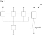
- the device can have a laser source 12 or can be arranged in the beam path of a laser beam from a laser source 12 .
- the laser beam can be, for example, a continuous laser beam or a pulsed laser beam (eg an ultrashort pulse laser beam).
- the device 10 further includes a parallel displacement unit 14, a beam deflection unit 16 and a focusing device 18, which in the case of 1 for example, are sequentially arranged in this order.
- the beam deflection unit 16 optionally has two movable mirrors (e.g. with galvanometer drive) for deflecting the laser beam along two directions.
- the first reflective mirror can provide a first deflection of the laser beam along a first direction, e.g., an x-direction, with respect to a surface of the workpiece 20. Accordingly, the first deflection can take place within a first angular range. The first deflection in the beam deflection unit can therefore initially take place in one dimension. If a second reflecting mirror is provided, this is optionally connected after the first reflecting mirror and is arranged in the beam path of the laser beam deflected by the first reflecting mirror.
- the initially one-dimensionally deflected laser beam can be deflected by means of the second reflecting mirror along a second direction, e.g.
- the second deflection can therefore take place within a second angular range and thus enable a two-dimensional deflection in the beam deflection unit 16 .
- Any path on the surface of the workpiece 20 can consequently be realized by superimposing the two deflections in the x-direction and y-direction.
- the workpiece 20 to be machined can be arranged and/or held in a workpiece holder 22 .
- the surface of the workpiece 20 can define an x-direction and/or a y-direction. Rapid and precise positioning in the x-direction and y-direction can thus be achieved with the aid of rapidly movable mirrors in the beam deflection unit 16, such as mirrors with a galvanometer drive. If there is a desired movement of the workpiece 20 relative to the laser, the workpiece holder 22 can be designed so that it can be moved with the aid of an adjusting means.
- the device 10 for laser material processing can have a control device 24 which is set up to control or regulate the parallel offset unit 14, the beam deflection unit 16 and/or the focusing device 18.
- sensors (not shown) are also provided for detecting parameters and/or status information, which can detect the position of the laser beam, for example. This enables improved adjustment of the laser beam for process optimization or calibration.
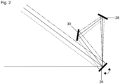
- the parallel-displacement unit includes a rotatable reflecting mirror (eg, galvanometer driven) 26 and two fixed reflecting mirrors 28 and 30.
- FIG. it may be the case that a laser beam to be displaced, coming from the bottom left, first hits the rotatable, reflecting mirror 26, is deflected towards a first fixed mirror 28 and then to a second fixed mirror 30 and finally again at the rotatable mirror , reflecting mirror 26 is reflected.
- the laser beams circulating in the mirror arrangement diverge from one another in relation to an optical axis until they are reflected again at the rotatable, reflecting mirror.
- the achievable parallel offset (or parallel displacement) per angle of rotation of the rotatable mirror can be adjusted as a function of the distance between the mirrors.
- the parallel offset unit 14 can be designed in such a way that the laser beam is reflected four times by means of the mirror arrangement.
- the entry and exit reflection, ie the first and the last reflection, in the parallel displacement unit 14 can take place at the rotatable, reflecting mirror 26 .
- the parallel offset unit can also be implemented with a different even number of fixed mirrors.
- the mirrors 26, 28, 30 of the parallel offset unit 14 are arranged essentially in a triangular shape.
- the mirrors 26, 28, 30 are set up in such a way that the laser beam incident on the parallel offset unit 14, the beams circulating in the parallel offset unit 14 and/or the laser beam emerging from the parallel offset unit 14 are substantially coplanar or lie in one plane.
- the mirrors 26, 28, 30 of the parallel displacement unit 14 can be arranged in such a way that the normals on the mirror surfaces of the mirrors of the parallel displacement unit (in other words the surface normals of the mirrors) lie in one plane.
- the reflecting mirrors of the parallel offset unit 14 and the mirror(s) of the beam deflection unit 16 are optionally designed as plane mirrors, that is to say essentially without surface curvature. Furthermore, the mirrors can have one or more coatings for specific laser wavelengths and/or laser powers.
- the rotatable mirror 26 of the parallel displacement unit 14 and/or the mirror(s) for deflection in the beam deflection unit 16 are further optionally configured for a low moment of inertia. In the beam deflection unit 16, this enables rapid positioning of the mirror(s) for deflecting laser beams, and in the translation unit 14, this enables rapid translation (or translation) of laser beams to adjust the angle of incidence of the laser beam axis.
- two parallel displacement units are connected in series and optically coupled to one another in such a way that the laser beam can be displaced parallel (or . movable) is.
- the further (second) parallel offset unit has at least three reflecting mirrors, one reflecting mirror of the at least three reflecting mirrors being rotatable for the parallel offset of the laser beam in the second parallel offset unit.
- the arrangement of the mirrors of the two parallel offset units is such that the laser beam incident on the first parallel offset unit 14, the beams circulating in the first parallel offset unit 14 and/or the beams from the first parallel -offset unit 14 are substantially coplanar with the laser beam incident on the second parallel offset unit 14, the rays circulating in the second parallel offset unit 14 and/or the laser beam emerging from the second parallel offset unit 14 exiting laser beam are substantially coplanar.
- the mirrors 26, 28, 30 of the first and the second parallel displacement unit 14 can be so be arranged in such a way that the normals on the mirror surfaces lie in one plane.
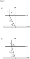
- Fig. 12 is a schematic view explaining how adjusting the offset (or parallel translation) varies the angle of incidence of the laser beam axis on the workpiece.
- the laser beam L represents the laser beam offset (or shifted) parallel to the optical axis oA by means of the parallel offset unit 14.
- This parallel offset laser beam L can—as in 3 shown - hit the focusing device (eg a lens) 18 .
- the beam deflection unit 16 for guiding the laser beam on the workpiece surface between the parallel offset unit 14 and the focusing device 18, namely immediately after the parallel offset unit 14 and immediately before the focusing device 18.
- the distance d of the radial impingement point of the laser beam L on the focusing device 18 to the optical axis oA can be set by offsetting (or shifting) the laser beam L parallel to the optical axis oA using the parallel offset unit 14 .
- the angle of inclination ⁇ , at which the laser beam emerges from the focusing device 18, varies—as in FIG 3 clarified - with the distance d of the radial impingement point of the laser beam L to the optical axis oA. If the position of the workpiece WS is not changed, the angle of incidence ⁇ of the laser beam axis on the workpiece WS also changes with the angle of inclination ⁇ at which the laser beam axis emerges from the focusing device 18 .
- the laser beam L hits the focusing device 18 parallel to the optical axis oA, i.e. without being deflected by the beam deflection unit 16, the laser focus, which is positioned on the workpiece surface for processing, is on the optical axis oA. If the laser beam L is inclined towards the optical axis oA when it strikes the focusing device 18, then the laser focus, which is positioned on the workpiece surface for processing, is not on the optical axis oA.
- the device for laser material processing can be a Beam shaping device (for example a beam expansion device) 32, a polarizer device 34, a device for shifting the focus position 36 and a beam splitter 38.
- a Beam shaping device for example a beam expansion device
- a polarizer device 34 for shifting the focus position 36
- a beam splitter 38 for shifting the focus position 36 and a beam splitter 38.
- the beam shaping device 32 for changing the laser beam diameter can be arranged in front of, optionally directly in front of, the parallel offset unit 14 in the propagation direction of the laser beam.
- the beam shaping device (e.g. the beam expansion device or beam reduction device) 32 can be implemented by a telescope, for example.
- the arrangement of the beam shaping device 32 can be such that it is connected between the laser source 12 and the polarizer device 34, optionally directly after the laser source 12 or optionally directly before the polarizer device 34. If a beam shaping device 32 is provided in the form of a beam expansion device, it can generate a larger laser beam diameter, which enables a smaller laser focus diameter via the focusing device 18 (e.g. a single lens or a lens system).
- the polarizer device 34 can be arranged in the propagation direction of the laser beam before, optionally immediately before, the parallel offset unit 14 and after, optionally immediately after, the beam shaping device 32 .
- the polarizer device 34 includes an assembly that enables a desired type of polarization to be set, for example linear polarization or circular polarization or elliptical polarization.
- the polarizer device can include a movement means that enables dynamic adjustment of the polarization that is adapted to the movement of the beam.
- the device 10 for laser material processing can also have a device for shifting the focal position 36, by means of which the focal position can be shifted along the optical axis, ie along the z-direction shown.
- the device for shifting the focus position 36 can be arranged in front of the focusing device 18 and optionally immediately before or immediately after the beam deflection unit 16 in the propagation direction of the laser beam.
- the device for shifting the focus position 36 may have an optical element or an optical assembly which is displaceable along the direction of propagation of the laser beam relative to (eg fixed) optics.
- the focusing device 18 can also be designed to be movable by means of an adjusting means, in order to enable the working distance to be continuously adjusted.
- the focal position on the workpiece 20 can be varied by means of the device for shifting the focal position 36 and processing of the workpiece 20 along a z-direction (ie along an optical axis) can be implemented.
- a beam splitter 38 is optionally provided, which is designed such that the laser beam and/or electromagnetic radiation (e.g. light) detected via the focusing device 18 can be decoupled from the beam path of the laser, for example for beam monitoring or process monitoring.
- the beam splitter 38 is arranged, for example, in the propagation direction of the laser beam after the beam deflection unit 16 and before, optionally immediately before, the focusing device 18 .
- the laser beam coupled out at this point and/or the electromagnetic radiation (e.g. light) coupled out, which is detected via the focusing device 18, can be directed to an optionally provided observation device (not shown).
- the electromagnetic radiation e.g. light
- the observation device can also have a camera sensor which is optically coupled to the beam splitter 38 via a camera lens, for example.
- the laser beam and/or the electromagnetic radiation (e.g. light) of the workpiece surface detected via the focusing device 18 can then be guided to the beam splitter 38, decoupled from the beam path of the laser at the beam splitter 38 and finally directed to the camera sensor for process monitoring.
- the control device 24 can be designed and set up in such a way that the parallel offset unit 14, the beam deflection unit 16, the focusing device 18 and, if necessary, other components such as the laser source 12, the device for shifting the focus position 36, the beam shaping device 32 and the polarizer device 34 are activated.
- the focusing device 18 for focusing the laser beam can be designed as a single lens, lens system or mirror system.
- the focusing device 18 is preferably designed to be fixed and the focus position is then varied by the device for shifting the focus position 36 .
- the device for shifting the focus position 36 can be connected between the parallel offset unit 14 and the beam deflection unit 16, optionally immediately after the parallel offset unit 14 or optionally immediately before the beam deflection unit 16.
- the other components can also be designed as explained above.
- the focusing device 18 can in principle also be arranged in front of, optionally directly in front of, the beam deflection unit 16 . Furthermore, the focusing device 18 can also be combined with the device for shifting the focus position 36 and designed in an integrated manner.
- the beam splitter 38 explained above can also be arranged at a different point in the beam path of the laser.
- the beam splitter 38 can be arranged in such a way that the laser beam can be coupled out in front of, optionally immediately in front of, the focusing device 18 when viewed in the direction of propagation.
- the parallel offset unit 14, the beam deflection unit 16, the focusing device 18 and, if necessary, other components such as the laser source 12, beam shaping device 32, polarizer device 34, device for shifting the focus position 36 and beam splitter 38 can be of modular design and designed to be interchangeable.
- the device 10 for laser material processing has a gas nozzle which is designed to generate a directed gas jet onto the workpiece surface. This makes it possible to improve the processing quality.
- a gas nozzle which is designed to generate a directed gas jet onto the workpiece surface.
- an inert or inert gas such as nitrogen can be used as the gas.
- the design of the gas nozzle can be adapted to the laser machining process.
- a beam rotator is also optionally provided, which is designed to generate an intensity profile of the laser beam that rotates about an axis of rotation.
- the beam rotator can have one or more rotating optical elements in succession in the propagation direction of the laser beam.
- the beam rotator can be implemented in particular by means of a prism or mirror arrangement, for example a turning prism (Dove prism).
- Dove prism The rotation of the intensity distribution of the laser beam improves the roundness of the holes in particular.
- the control device 24 can also be set up in such a way that a synchronized activation of the beam deflection unit 16, the parallel offset unit 14, the focusing device 18, the device for shifting the focus position 36 and/or the laser source 12 is implemented.
- the components can be controlled digitally, in particular, with separate control cards optionally being provided for the individual components (e.g. the beam deflection unit, parallel offset unit, etc.).
- the control cards can be controlled via a central control device, e.g. suitable software on a computer or a computer-independent control unit. The control cards ensure synchronous and interference-free control of the components.
- the device for laser material processing can optionally be a device for laser material processing for drilling, optionally micro-drilling, where the drilling diameter can be in the micrometer range, optionally below 500 ⁇ m or optionally below 200 ⁇ m .
- the present invention can also relate to a device for laser material processing (or laser material processing device) in combination with a material to be processed, optionally with a plate material to be laser processed.
Landscapes
- Physics & Mathematics (AREA)
- Optics & Photonics (AREA)
- Engineering & Computer Science (AREA)
- Plasma & Fusion (AREA)
- Mechanical Engineering (AREA)
- Laser Beam Processing (AREA)
Claims (15)
- Dispositif (10) pour l'usinage de matériau par laser, présentant
une unité de déflexion de faisceau (16) avec au moins un miroir réfléchissant, qui est réalisé sous forme de miroir rotatif ou basculant, pour dévier un faisceau laser, qui définit un axe de faisceau laser, le long d'une première direction par rapport à une surface d'une pièce à usiner (20) à traiter, pour le guidage de trajectoire du faisceau laser sur la surface de la pièce à usiner (20),
caractérisé par :une unité de décalage parallèle (14) avec au moins trois miroirs réfléchissants (26, 28, 30) pour le coulissement parallèle du faisceau laser, par rapport à un axe optique (oA), le long d'une première direction de déplacement parallèle, un miroir réfléchissant (26) des au moins trois miroirs réfléchissants pouvant être tourné pour le déplacement parallèle du faisceau laser et la réflexion d'entrée et la réflexion de sortie ayant lieu sur le miroir réfléchissant rotatif (26),une autre unité de décalage parallèle, qui est conçue comme l'unité de décalage parallèle (14), pour le coulissement parallèle du faisceau laser le long d'une deuxième direction de déplacement parallèle, les unités de décalage parallèle étant couplées optiquement entre elles de telle sorte que le faisceau laser puisse être décalé parallèlement le long de deux directions de décalage parallèle différentes, etun dispositif de focalisation (18) pour focaliser sur la pièce à usiner (20) le faisceau laser déplacé en parallèle au moyen des unités de décalage parallèle et dévié au moyen de l'unité de déviation de faisceau (16), dans lequell'angle d'incidence de l'axe du faisceau laser sur la pièce à usiner peut être varié dans deux directions spatiales grâce au réglage des déplacements parallèles effectués au moyen des unités de décalage parallèle. - Dispositif selon la revendication 1, dans lequel l'unité de déviation de faisceau (16) présente un deuxième miroir réfléchissant, qui est réalisé sous forme de miroir rotatif ou basculant et qui est monté en aval du premier miroir réfléchissant dans la trajectoire du faisceau, pour dévier le faisceau laser le long d'une deuxième direction par rapport à la surface de la pièce à usiner. Le faisceau laser est dévié dans une deuxième direction par rapport à la surface de la pièce à usiner (20), ce qui permet une déviation bidimensionnelle du faisceau laser pour le guidage de trajectoire correspondant du faisceau laser sur la surface de la pièce à usiner (20).
- Dispositif selon la revendication 1 ou 2, dans lequel l'unité de décalage parallèle (14) est réalisée avec un nombre pair de miroirs fixes.
- Dispositif selon l'une quelconque des revendications 1 à 3, dans lequel l'unité de décalage parallèle (14) est configurée de telle sorte que le faisceau laser est réfléchi quatre fois au moyen de l'agencement de miroirs.
- Dispositif selon l'une quelconque des revendications 1 à 4, pour lequel les miroirs (26, 28, 30) de l'unité de décalage parallèle (14) sont conçus de sorte que les normales aux surfaces de miroir des miroirs de l'unité de décalage parallèle se situent dans un plan.
- Dispositif selon l'une quelconque des revendications 1 à 5 avec un système pour le coulissement de position focale (36) du faisceau laser, qui est disposé dans la direction de propagation du faisceau laser avant le système de focalisation (18) et éventuellement après l'unité de déflexion de faisceau (16).
- Dispositif selon l'une quelconque des revendications 1 à 6, comprenant un dispositif de commande (24) agencé de manière à mettre en oeuvre une commande synchronisée de l'unité de déviation de faisceau (16), de l'unité de décalage parallèle (14), du dispositif de focalisation (18), d'un dispositif de déplacement de position focale (36) et/ou d'une source laser (12).
- Dispositif selon l'une quelconque des revendications 1 à 7 avec un séparateur de faisceau (38), qui est prévu dans la direction de propagation du faisceau laser avant, éventuellement immédiatement avant, le système de focalisation (18) est conçu pour extraire le faisceau laser et/ou le rayonnement électromagnétique détecté par l'intermédiaire du système de focalisation (18) du trajet optique du laser.
- Dispositif selon la revendication 8 avec un système d'observation, qui est couplé optiquement au séparateur de faisceau (38) et est conçu pour détecter le faisceau laser extrait et/ou le rayonnement électromagnétique extrait.
- Dispositif selon l'une quelconque des revendications 1 à 9, dans lequel un système de formation de faisceau (32) pour la modification du diamètre de faisceau laser est prévu, qui est disposé dans la direction de propagation du faisceau laser avant l'unité de décalage parallèle (14).
- Dispositif selon l'une des revendications 1 à 10, dans lequel un système polariseur (34) est prévu, qui est disposé dans la direction de propagation du faisceau laser avant l'unité de décalage parallèle (14) et éventuellement après le système de formation de faisceau (32).
- Dispositif selon l'une quelconque des revendications 1 à 11, dans lequel l'unité de déflexion de faisceau (16) est disposée entre l'unité de décalage parallèle (14) et le système de focalisation (18) éventuellement immédiatement après l'unité de décalage parallèle (14) ou éventuellement immédiatement avant le système de focalisation (18).
- Dispositif selon l'une quelconque des revendications 1 à 12, présentant en outre un porte-pièce (22), dans lequel la pièce (20) est disposée et/ou retenue.
- Dispositif pour l'usinage de matériau par laser selon l'une quelconque des revendications précédentes en combinaison avec une pièce (20) à usiner.
- Utilisation d'un dispositif selon l'une des revendications 1 à 14 pour l'usinage de matériau par laser.
Applications Claiming Priority (3)
| Application Number | Priority Date | Filing Date | Title |
|---|---|---|---|
| DE102014108259.1A DE102014108259A1 (de) | 2014-06-12 | 2014-06-12 | Vorrichtung zur Lasermaterialbearbeitung |
| EP15731863.5A EP3154740B1 (fr) | 2014-06-12 | 2015-06-10 | Dispositif d'usinage de matériaux par laser à unité à déplacement parallèle |
| PCT/EP2015/062888 WO2015189241A1 (fr) | 2014-06-12 | 2015-06-10 | Dispositif d'usinage de matériaux par laser à unité à déplacement parallèle |
Related Parent Applications (2)
| Application Number | Title | Priority Date | Filing Date |
|---|---|---|---|
| EP15731863.5A Division EP3154740B1 (fr) | 2014-06-12 | 2015-06-10 | Dispositif d'usinage de matériaux par laser à unité à déplacement parallèle |
| EP15731863.5A Division-Into EP3154740B1 (fr) | 2014-06-12 | 2015-06-10 | Dispositif d'usinage de matériaux par laser à unité à déplacement parallèle |
Publications (2)
| Publication Number | Publication Date |
|---|---|
| EP3932609A1 EP3932609A1 (fr) | 2022-01-05 |
| EP3932609B1 true EP3932609B1 (fr) | 2023-04-26 |
Family
ID=53489928
Family Applications (2)
| Application Number | Title | Priority Date | Filing Date |
|---|---|---|---|
| EP15731863.5A Active EP3154740B1 (fr) | 2014-06-12 | 2015-06-10 | Dispositif d'usinage de matériaux par laser à unité à déplacement parallèle |
| EP21188134.7A Active EP3932609B1 (fr) | 2014-06-12 | 2015-06-10 | Dispositif d'usinage laser des matériaux avec deux unitées de décalage parallèle du faisceau laser |
Family Applications Before (1)
| Application Number | Title | Priority Date | Filing Date |
|---|---|---|---|
| EP15731863.5A Active EP3154740B1 (fr) | 2014-06-12 | 2015-06-10 | Dispositif d'usinage de matériaux par laser à unité à déplacement parallèle |
Country Status (7)
| Country | Link |
|---|---|
| US (1) | US10272521B2 (fr) |
| EP (2) | EP3154740B1 (fr) |
| JP (1) | JP6680773B2 (fr) |
| KR (1) | KR102442690B1 (fr) |
| CN (1) | CN107073645B (fr) |
| DE (1) | DE102014108259A1 (fr) |
| WO (1) | WO2015189241A1 (fr) |
Families Citing this family (10)
| Publication number | Priority date | Publication date | Assignee | Title |
|---|---|---|---|---|
| EP4177000B1 (fr) * | 2015-08-14 | 2024-08-21 | Laser Engineering Applications | Dispositif d'usinage |
| CN109791303A (zh) * | 2016-07-15 | 2019-05-21 | 特拉迪欧德公司 | 利用可变光束形状的激光的材料加工 |
| BE1025341B1 (fr) * | 2017-06-27 | 2019-02-04 | LASER ENGINEERING APPLICATIONS S.A. en abrégé LASEA S.A. | Méthode pour structurer un substrat |
| US10705327B2 (en) | 2018-01-02 | 2020-07-07 | Industrial Technology Research Institute | Light emitting method and light emitting device |
| CN110625274B (zh) * | 2019-11-05 | 2021-12-21 | 南京先进激光技术研究院 | 一种密集孔激光精密加工方法 |
| CN115916450A (zh) * | 2020-08-18 | 2023-04-04 | 株式会社 尼康 | 光学装置及加工装置 |
| CN112296537B (zh) * | 2020-10-23 | 2022-05-17 | 中国空气动力研究与发展中心高速空气动力研究所 | 一种转捩带切割激光发射对位装置 |
| EP4032652B1 (fr) * | 2021-01-26 | 2024-10-09 | Precitec GmbH & Co. KG | Système et procédé d'usinage de matière au moyen d'un faisceau laser oscillant |
| CN117718603B (zh) * | 2024-01-16 | 2025-09-02 | 江苏乐希激光装备有限公司 | 一种可调焦切割装置 |
| CN118789098A (zh) * | 2024-08-21 | 2024-10-18 | 厦门大学 | 基于折射反射混合式光束平移单元的变入射角激光加工装置与加工方法 |
Family Cites Families (41)
| Publication number | Priority date | Publication date | Assignee | Title |
|---|---|---|---|---|
| US2000321A (en) * | 1933-10-20 | 1935-05-07 | North American Chemical Compan | Magazine shoe filler unit |
| US3742182A (en) * | 1971-12-27 | 1973-06-26 | Coherent Radiation | Method for scanning mask forming holes with a laser beam |
| CA1107105A (fr) | 1977-06-10 | 1981-08-18 | Steven K. Harbaugh | Lecteur optique et systeme d'exposition a rayon laser pour surfaces photosensibles |
| US4323307A (en) | 1980-06-06 | 1982-04-06 | American Hoechst Corporation | Light beam scanning apparatus |
| US4655547A (en) * | 1985-04-09 | 1987-04-07 | Bell Communications Research, Inc. | Shaping optical pulses by amplitude and phase masking |
| DE3709351A1 (de) * | 1987-03-21 | 1988-09-29 | Heraeus Gmbh W C | Strahlfuehrungsoptik fuer laserstrahlung |
| JPH0616952B2 (ja) | 1988-08-05 | 1994-03-09 | 日本電気株式会社 | レーザ光エネルギー管理方法 |
| US5017755A (en) * | 1988-10-26 | 1991-05-21 | Kabushiki Kaisha Toshiba | Method of repairing liquid crystal display and apparatus using the method |
| JPH0757427B2 (ja) | 1989-12-08 | 1995-06-21 | 三菱電機株式会社 | レーザ切断加工機 |
| JPH05228673A (ja) * | 1992-02-18 | 1993-09-07 | Toshiba Corp | レ−ザ−加工装置 |
| DE4404141A1 (de) * | 1994-02-09 | 1995-08-10 | Fraunhofer Ges Forschung | Vorrichtung und Verfahren zur Laserstrahlformung, insbesondere bei der Laserstrahl-Oberflächenbearbeitung |
| JP2993479B2 (ja) | 1997-10-09 | 1999-12-20 | 日本電気株式会社 | レーザパワーモニタ装置 |
| JPH11156567A (ja) | 1997-12-02 | 1999-06-15 | Fuji Electric Co Ltd | レーザ印字装置 |
| JP2003161907A (ja) | 2001-11-28 | 2003-06-06 | Sunx Ltd | レーザビーム径可変装置 |
| US7405114B2 (en) * | 2002-10-16 | 2008-07-29 | Semiconductor Energy Laboratory Co., Ltd. | Laser irradiation apparatus and method of manufacturing semiconductor device |
| JP3822188B2 (ja) * | 2002-12-26 | 2006-09-13 | 日立ビアメカニクス株式会社 | 多重ビームレーザ穴あけ加工装置 |
| JP4299185B2 (ja) * | 2004-04-27 | 2009-07-22 | 株式会社ディスコ | レーザー加工装置 |
| US20080124816A1 (en) * | 2004-06-18 | 2008-05-29 | Electro Scientific Industries, Inc. | Systems and methods for semiconductor structure processing using multiple laser beam spots |
| DE102004053298B4 (de) | 2004-08-26 | 2008-10-09 | ARGES Gesellschaft für Industrieplanung und Lasertechnik m.b.H. | Scankopf als Teil einer Laser Bohr- und Schneideinrichtung |
| US7371596B2 (en) * | 2004-12-30 | 2008-05-13 | Semicube, Inc. | Parallel-beam scanning for surface patterning of materials |
| DE202005006838U1 (de) * | 2005-04-29 | 2006-08-31 | Trumpf Werkzeugmaschinen Gmbh + Co. Kg | Optisches Modul zum Einbau in den Laser einer Laserbearbeitungsmaschine |
| DE102005047328B3 (de) | 2005-06-28 | 2006-12-07 | Fraunhofer-Gesellschaft zur Förderung der angewandten Forschung e.V. | Vorrichtung zum Bohren und für den Materialabtrag mittels Laserstrahl |
| JP4691166B2 (ja) * | 2005-12-23 | 2011-06-01 | トルンプフ ヴェルクツォイクマシーネン ゲゼルシャフト ミット ベシュレンクテル ハフツング ウント コンパニー コマンディートゲゼルシャフト | スキャナヘッド及び当該スキャナヘッドを用いた加工機器 |
| KR100819616B1 (ko) * | 2006-03-13 | 2008-04-04 | 미쓰비시덴키 가부시키가이샤 | 레이저 가공 장치 |
| JP4402708B2 (ja) * | 2007-08-03 | 2010-01-20 | 浜松ホトニクス株式会社 | レーザ加工方法、レーザ加工装置及びその製造方法 |
| CN101786200B (zh) | 2010-02-26 | 2012-01-25 | 华中科技大学 | 一种自由曲面上的投影式激光刻蚀方法 |
| CN101870039B (zh) * | 2010-06-12 | 2014-01-22 | 中国电子科技集团公司第四十五研究所 | 双工作台驱动激光加工机及其加工方法 |
| DE102010032958A1 (de) * | 2010-07-30 | 2012-02-02 | Messer Cutting & Welding Gmbh | Verfahren und Vorrichtung zum thermischen Bearbeiten eines Werkstücks mittels Laserstrahl |
| DE102010049460A1 (de) | 2010-09-13 | 2012-03-15 | Laser- Und Medizin-Technologie Gmbh, Berlin | Trepanieroptik |
| CN102000917B (zh) | 2010-10-25 | 2013-04-24 | 苏州德龙激光股份有限公司 | Led晶圆激光内切割划片设备 |
| CN103534631A (zh) | 2011-03-01 | 2014-01-22 | 应用精密公司 | 激光束辐照度控制系统 |
| DE102011006152A1 (de) * | 2011-03-25 | 2012-09-27 | BLZ Bayerisches Laserzentrum Gemeinnützige Forschungsgesellschaft mbH | Trepanieroptik zur Einstellung und Variation eines Propagationswinkels und einer lateralen Versetzung elektromagnetischer Strahlung |
| EP2780753B1 (fr) * | 2011-11-15 | 2017-09-13 | GE Healthcare Biocience Bio-Process Corp | Système d'éclairage à commutation de modes |
| DE102012101643A1 (de) * | 2012-02-29 | 2013-08-29 | Scanlab Ag | Vorrichtung und Verfahren zum Ablenken von elektro-magnetischer Strahlung, Vorrichtung und Verfahren zum Bestrahlen eines Körpers |
| JP2013230478A (ja) * | 2012-04-27 | 2013-11-14 | Disco Corp | レーザー加工装置及びレーザー加工方法 |
| DE102012111090B4 (de) * | 2012-11-19 | 2021-04-29 | Scanlab Gmbh | Vorrichtung zum Ändern der Länge eines Strahlenganges, Fokussiervorrichtung und Strahllage-und-Strahldivergenz-Änderungsvorrichtung |
| CN203221280U (zh) * | 2013-02-19 | 2013-10-02 | 深圳市海目星激光科技有限公司 | 一种紫外激光加工装置 |
| DE102013210078B4 (de) * | 2013-05-29 | 2015-04-30 | Trumpf Werkzeugmaschinen Gmbh + Co. Kg | Vorrichtung, Verfahren und Computerprogrammprodukt zur Bestimmung der Fokusposition eines Hochenergiestrahls |
| DE102013218421A1 (de) * | 2013-09-13 | 2015-04-02 | Trumpf Werkzeugmaschinen Gmbh + Co. Kg | Vorrichtung und Verfahren zur Überwachung, insbesondere zur Regelung, eines Schneidprozesses |
| CN103692090A (zh) * | 2013-12-19 | 2014-04-02 | 苏州德龙激光股份有限公司 | 触控面板用loca胶的激光切割装置和方法 |
| US11453657B2 (en) * | 2018-01-24 | 2022-09-27 | Glaxosmithkline Intellectual Property Development Limited | Compounds for the treatment of parasitic infections |
-
2014
- 2014-06-12 DE DE102014108259.1A patent/DE102014108259A1/de not_active Withdrawn
-
2015
- 2015-06-10 CN CN201580031454.8A patent/CN107073645B/zh active Active
- 2015-06-10 JP JP2017517400A patent/JP6680773B2/ja active Active
- 2015-06-10 KR KR1020167036729A patent/KR102442690B1/ko active Active
- 2015-06-10 US US15/315,657 patent/US10272521B2/en active Active
- 2015-06-10 EP EP15731863.5A patent/EP3154740B1/fr active Active
- 2015-06-10 WO PCT/EP2015/062888 patent/WO2015189241A1/fr not_active Ceased
- 2015-06-10 EP EP21188134.7A patent/EP3932609B1/fr active Active
Also Published As
| Publication number | Publication date |
|---|---|
| JP6680773B2 (ja) | 2020-04-15 |
| KR102442690B1 (ko) | 2022-09-13 |
| KR20170015369A (ko) | 2017-02-08 |
| JP2017521264A (ja) | 2017-08-03 |
| EP3154740B1 (fr) | 2021-10-13 |
| EP3932609A1 (fr) | 2022-01-05 |
| EP3154740A1 (fr) | 2017-04-19 |
| WO2015189241A1 (fr) | 2015-12-17 |
| CN107073645B (zh) | 2020-01-21 |
| US20170157705A1 (en) | 2017-06-08 |
| CN107073645A (zh) | 2017-08-18 |
| DE102014108259A1 (de) | 2015-12-17 |
| US10272521B2 (en) | 2019-04-30 |
Similar Documents
| Publication | Publication Date | Title |
|---|---|---|
| EP3154740B1 (fr) | Dispositif d'usinage de matériaux par laser à unité à déplacement parallèle | |
| EP2673106B1 (fr) | Dispositif, sytème et méthode pour la texturation de pièces plates par interférences lumineuses | |
| DE10018253C2 (de) | Laser-Mikro-Dissektionsgerät | |
| DE102013015656B4 (de) | Verfahren zum Messen der Eindringtiefe eines Laserstrahls in ein Werkstück, Verfahren zum Bearbeiten eines Werkstücks sowie Laserbearbeitungsvorrichtung | |
| EP3463741B1 (fr) | Dispositif de surveillance de processus lors de l'usinage laser comprenant un dispositif de mesure de distance optique et une unité de déflexion à prismes, tête d'usinage laser équipée d'un tel dispositif | |
| EP3069186B1 (fr) | Dispositif et procédé de guidage d'un faisceau laser | |
| EP2596899B1 (fr) | Dispositif et procédé de structuration par interférences d'échantillons plats | |
| DE102012011343B4 (de) | Vorrichtung zur Interferenzstrukturierung von Proben | |
| WO2018078137A1 (fr) | Unité de déviation comprenant deux fenêtres, un élément optique et un dispositif de déviation xy | |
| DE102013008269A1 (de) | Bearbeitungskopf für eine Laserbearbeitungsvorrichtung | |
| DE202008017745U1 (de) | Vorrichtung zum Führen eines Lichtstrahls | |
| DE60006586T2 (de) | Laserstrahlvorrichtung zum zielen und verfahren zum schneiden oder markieren eines werkstücks | |
| DE102007012695A1 (de) | Verfahren und Vorrichtung zur schnellen Ablenkung eines Lichtstrahles auf eine einstellbare Kreisbahn | |
| DE102016008184B4 (de) | Messvorrichtung und Verfahren zum Überwachen eines Bearbeitungsprozesses zur Materialbearbeitung eines Werkstücks unter synchroner Ansteuerung eines Bearbeitungsscanners und eines Referenzarmscanners sowie System zum Bearbeiten und Überwachen eines Werkstücks mit einer Messvorrichtung | |
| DE102012004312A1 (de) | Verfahren und Vorrichtung zur schnellen konzentrischen Ablenkung mehrerer Lichtstrahlen mit einstellbarem Winkel um die Systemachse | |
| DE102014012456A1 (de) | Optische Strahlführungseinheit und Materialbearbeitungsvorrichtung mit einer optischen Strahlführungseinheit | |
| EP4096860B1 (fr) | Ensemble de traitement de matériau à l'aide d'un faisceau laser, notamment destiné au perçage par laser | |
| DE102007014933A1 (de) | Verfahren und Vorrichtung zur schnellen Ablenkung eines Lichtstrahles auf eine einstellbare Längsbahn | |
| DE102022127259B4 (de) | Verfahren sowie Vorrichtung zur Abbildung eines Strahls auf ein Objekt und Verfahren zum Einbringen einer Öffnung in ein Werkstück mittels dieses Verfahrens | |
| EP3030375B1 (fr) | Dispositif d'usinage de matière par faisceau laser | |
| EP4137262B1 (fr) | Procédé et dispositif de découpage laser d'une pièce |
Legal Events
| Date | Code | Title | Description |
|---|---|---|---|
| PUAI | Public reference made under article 153(3) epc to a published international application that has entered the european phase |
Free format text: ORIGINAL CODE: 0009012 |
|
| STAA | Information on the status of an ep patent application or granted ep patent |
Free format text: STATUS: THE APPLICATION HAS BEEN PUBLISHED |
|
| AC | Divisional application: reference to earlier application |
Ref document number: 3154740 Country of ref document: EP Kind code of ref document: P |
|
| AK | Designated contracting states |
Kind code of ref document: A1 Designated state(s): AL AT BE BG CH CY CZ DE DK EE ES FI FR GB GR HR HU IE IS IT LI LT LU LV MC MK MT NL NO PL PT RO RS SE SI SK SM TR |
|
| B565 | Issuance of search results under rule 164(2) epc |
Effective date: 20211202 |
|
| STAA | Information on the status of an ep patent application or granted ep patent |
Free format text: STATUS: REQUEST FOR EXAMINATION WAS MADE |
|
| 17P | Request for examination filed |
Effective date: 20220622 |
|
| RBV | Designated contracting states (corrected) |
Designated state(s): AL AT BE BG CH CY CZ DE DK EE ES FI FR GB GR HR HU IE IS IT LI LT LU LV MC MK MT NL NO PL PT RO RS SE SI SK SM TR |
|
| GRAP | Despatch of communication of intention to grant a patent |
Free format text: ORIGINAL CODE: EPIDOSNIGR1 |
|
| STAA | Information on the status of an ep patent application or granted ep patent |
Free format text: STATUS: GRANT OF PATENT IS INTENDED |
|
| INTG | Intention to grant announced |
Effective date: 20221129 |
|
| GRAS | Grant fee paid |
Free format text: ORIGINAL CODE: EPIDOSNIGR3 |
|
| GRAA | (expected) grant |
Free format text: ORIGINAL CODE: 0009210 |
|
| STAA | Information on the status of an ep patent application or granted ep patent |
Free format text: STATUS: THE PATENT HAS BEEN GRANTED |
|
| AC | Divisional application: reference to earlier application |
Ref document number: 3154740 Country of ref document: EP Kind code of ref document: P |
|
| AK | Designated contracting states |
Kind code of ref document: B1 Designated state(s): AL AT BE BG CH CY CZ DE DK EE ES FI FR GB GR HR HU IE IS IT LI LT LU LV MC MK MT NL NO PL PT RO RS SE SI SK SM TR |
|
| REG | Reference to a national code |
Ref country code: GB Ref legal event code: FG4D Free format text: NOT ENGLISH |
|
| REG | Reference to a national code |
Ref country code: CH Ref legal event code: EP |
|
| REG | Reference to a national code |
Ref country code: DE Ref legal event code: R096 Ref document number: 502015016336 Country of ref document: DE |
|
| REG | Reference to a national code |
Ref country code: AT Ref legal event code: REF Ref document number: 1562489 Country of ref document: AT Kind code of ref document: T Effective date: 20230515 |
|
| REG | Reference to a national code |
Ref country code: IE Ref legal event code: FG4D Free format text: LANGUAGE OF EP DOCUMENT: GERMAN |
|
| REG | Reference to a national code |
Ref country code: LT Ref legal event code: MG9D |
|
| REG | Reference to a national code |
Ref country code: NL Ref legal event code: MP Effective date: 20230426 |
|
| PG25 | Lapsed in a contracting state [announced via postgrant information from national office to epo] |
Ref country code: NL Free format text: LAPSE BECAUSE OF FAILURE TO SUBMIT A TRANSLATION OF THE DESCRIPTION OR TO PAY THE FEE WITHIN THE PRESCRIBED TIME-LIMIT Effective date: 20230426 |
|
| PGFP | Annual fee paid to national office [announced via postgrant information from national office to epo] |
Ref country code: BE Payment date: 20230629 Year of fee payment: 9 |
|
| PG25 | Lapsed in a contracting state [announced via postgrant information from national office to epo] |
Ref country code: SE Free format text: LAPSE BECAUSE OF FAILURE TO SUBMIT A TRANSLATION OF THE DESCRIPTION OR TO PAY THE FEE WITHIN THE PRESCRIBED TIME-LIMIT Effective date: 20230426 Ref country code: PT Free format text: LAPSE BECAUSE OF FAILURE TO SUBMIT A TRANSLATION OF THE DESCRIPTION OR TO PAY THE FEE WITHIN THE PRESCRIBED TIME-LIMIT Effective date: 20230828 Ref country code: NO Free format text: LAPSE BECAUSE OF FAILURE TO SUBMIT A TRANSLATION OF THE DESCRIPTION OR TO PAY THE FEE WITHIN THE PRESCRIBED TIME-LIMIT Effective date: 20230726 Ref country code: ES Free format text: LAPSE BECAUSE OF FAILURE TO SUBMIT A TRANSLATION OF THE DESCRIPTION OR TO PAY THE FEE WITHIN THE PRESCRIBED TIME-LIMIT Effective date: 20230426 |
|
| PG25 | Lapsed in a contracting state [announced via postgrant information from national office to epo] |
Ref country code: RS Free format text: LAPSE BECAUSE OF FAILURE TO SUBMIT A TRANSLATION OF THE DESCRIPTION OR TO PAY THE FEE WITHIN THE PRESCRIBED TIME-LIMIT Effective date: 20230426 Ref country code: PL Free format text: LAPSE BECAUSE OF FAILURE TO SUBMIT A TRANSLATION OF THE DESCRIPTION OR TO PAY THE FEE WITHIN THE PRESCRIBED TIME-LIMIT Effective date: 20230426 Ref country code: LV Free format text: LAPSE BECAUSE OF FAILURE TO SUBMIT A TRANSLATION OF THE DESCRIPTION OR TO PAY THE FEE WITHIN THE PRESCRIBED TIME-LIMIT Effective date: 20230426 Ref country code: LT Free format text: LAPSE BECAUSE OF FAILURE TO SUBMIT A TRANSLATION OF THE DESCRIPTION OR TO PAY THE FEE WITHIN THE PRESCRIBED TIME-LIMIT Effective date: 20230426 Ref country code: IS Free format text: LAPSE BECAUSE OF FAILURE TO SUBMIT A TRANSLATION OF THE DESCRIPTION OR TO PAY THE FEE WITHIN THE PRESCRIBED TIME-LIMIT Effective date: 20230826 Ref country code: HR Free format text: LAPSE BECAUSE OF FAILURE TO SUBMIT A TRANSLATION OF THE DESCRIPTION OR TO PAY THE FEE WITHIN THE PRESCRIBED TIME-LIMIT Effective date: 20230426 Ref country code: GR Free format text: LAPSE BECAUSE OF FAILURE TO SUBMIT A TRANSLATION OF THE DESCRIPTION OR TO PAY THE FEE WITHIN THE PRESCRIBED TIME-LIMIT Effective date: 20230727 |
|
| PG25 | Lapsed in a contracting state [announced via postgrant information from national office to epo] |
Ref country code: FI Free format text: LAPSE BECAUSE OF FAILURE TO SUBMIT A TRANSLATION OF THE DESCRIPTION OR TO PAY THE FEE WITHIN THE PRESCRIBED TIME-LIMIT Effective date: 20230426 |
|
| PG25 | Lapsed in a contracting state [announced via postgrant information from national office to epo] |
Ref country code: SK Free format text: LAPSE BECAUSE OF FAILURE TO SUBMIT A TRANSLATION OF THE DESCRIPTION OR TO PAY THE FEE WITHIN THE PRESCRIBED TIME-LIMIT Effective date: 20230426 |
|
| PG25 | Lapsed in a contracting state [announced via postgrant information from national office to epo] |
Ref country code: MC Free format text: LAPSE BECAUSE OF FAILURE TO SUBMIT A TRANSLATION OF THE DESCRIPTION OR TO PAY THE FEE WITHIN THE PRESCRIBED TIME-LIMIT Effective date: 20230426 |
|
| REG | Reference to a national code |
Ref country code: DE Ref legal event code: R097 Ref document number: 502015016336 Country of ref document: DE |
|
| PG25 | Lapsed in a contracting state [announced via postgrant information from national office to epo] |
Ref country code: SM Free format text: LAPSE BECAUSE OF FAILURE TO SUBMIT A TRANSLATION OF THE DESCRIPTION OR TO PAY THE FEE WITHIN THE PRESCRIBED TIME-LIMIT Effective date: 20230426 Ref country code: SK Free format text: LAPSE BECAUSE OF FAILURE TO SUBMIT A TRANSLATION OF THE DESCRIPTION OR TO PAY THE FEE WITHIN THE PRESCRIBED TIME-LIMIT Effective date: 20230426 Ref country code: RO Free format text: LAPSE BECAUSE OF FAILURE TO SUBMIT A TRANSLATION OF THE DESCRIPTION OR TO PAY THE FEE WITHIN THE PRESCRIBED TIME-LIMIT Effective date: 20230426 Ref country code: MC Free format text: LAPSE BECAUSE OF FAILURE TO SUBMIT A TRANSLATION OF THE DESCRIPTION OR TO PAY THE FEE WITHIN THE PRESCRIBED TIME-LIMIT Effective date: 20230426 Ref country code: EE Free format text: LAPSE BECAUSE OF FAILURE TO SUBMIT A TRANSLATION OF THE DESCRIPTION OR TO PAY THE FEE WITHIN THE PRESCRIBED TIME-LIMIT Effective date: 20230426 Ref country code: DK Free format text: LAPSE BECAUSE OF FAILURE TO SUBMIT A TRANSLATION OF THE DESCRIPTION OR TO PAY THE FEE WITHIN THE PRESCRIBED TIME-LIMIT Effective date: 20230426 Ref country code: CZ Free format text: LAPSE BECAUSE OF FAILURE TO SUBMIT A TRANSLATION OF THE DESCRIPTION OR TO PAY THE FEE WITHIN THE PRESCRIBED TIME-LIMIT Effective date: 20230426 |
|
| PG25 | Lapsed in a contracting state [announced via postgrant information from national office to epo] |
Ref country code: LU Free format text: LAPSE BECAUSE OF NON-PAYMENT OF DUE FEES Effective date: 20230610 |
|
| PLBE | No opposition filed within time limit |
Free format text: ORIGINAL CODE: 0009261 |
|
| STAA | Information on the status of an ep patent application or granted ep patent |
Free format text: STATUS: NO OPPOSITION FILED WITHIN TIME LIMIT |
|
| GBPC | Gb: european patent ceased through non-payment of renewal fee |
Effective date: 20230726 |
|
| REG | Reference to a national code |
Ref country code: IE Ref legal event code: MM4A |
|
| PG25 | Lapsed in a contracting state [announced via postgrant information from national office to epo] |
Ref country code: LU Free format text: LAPSE BECAUSE OF NON-PAYMENT OF DUE FEES Effective date: 20230610 |
|
| 26N | No opposition filed |
Effective date: 20240129 |
|
| PG25 | Lapsed in a contracting state [announced via postgrant information from national office to epo] |
Ref country code: IE Free format text: LAPSE BECAUSE OF NON-PAYMENT OF DUE FEES Effective date: 20230610 |
|
| PG25 | Lapsed in a contracting state [announced via postgrant information from national office to epo] |
Ref country code: IE Free format text: LAPSE BECAUSE OF NON-PAYMENT OF DUE FEES Effective date: 20230610 Ref country code: GB Free format text: LAPSE BECAUSE OF NON-PAYMENT OF DUE FEES Effective date: 20230726 |
|
| PG25 | Lapsed in a contracting state [announced via postgrant information from national office to epo] |
Ref country code: SI Free format text: LAPSE BECAUSE OF FAILURE TO SUBMIT A TRANSLATION OF THE DESCRIPTION OR TO PAY THE FEE WITHIN THE PRESCRIBED TIME-LIMIT Effective date: 20230426 |
|
| PG25 | Lapsed in a contracting state [announced via postgrant information from national office to epo] |
Ref country code: SI Free format text: LAPSE BECAUSE OF FAILURE TO SUBMIT A TRANSLATION OF THE DESCRIPTION OR TO PAY THE FEE WITHIN THE PRESCRIBED TIME-LIMIT Effective date: 20230426 |
|
| REG | Reference to a national code |
Ref country code: AT Ref legal event code: MM01 Ref document number: 1562489 Country of ref document: AT Kind code of ref document: T Effective date: 20230610 |
|
| PG25 | Lapsed in a contracting state [announced via postgrant information from national office to epo] |
Ref country code: AT Free format text: LAPSE BECAUSE OF NON-PAYMENT OF DUE FEES Effective date: 20230610 |
|
| PG25 | Lapsed in a contracting state [announced via postgrant information from national office to epo] |
Ref country code: AT Free format text: LAPSE BECAUSE OF NON-PAYMENT OF DUE FEES Effective date: 20230610 |
|
| PG25 | Lapsed in a contracting state [announced via postgrant information from national office to epo] |
Ref country code: BG Free format text: LAPSE BECAUSE OF FAILURE TO SUBMIT A TRANSLATION OF THE DESCRIPTION OR TO PAY THE FEE WITHIN THE PRESCRIBED TIME-LIMIT Effective date: 20230426 |
|
| PG25 | Lapsed in a contracting state [announced via postgrant information from national office to epo] |
Ref country code: BG Free format text: LAPSE BECAUSE OF FAILURE TO SUBMIT A TRANSLATION OF THE DESCRIPTION OR TO PAY THE FEE WITHIN THE PRESCRIBED TIME-LIMIT Effective date: 20230426 |
|
| PG25 | Lapsed in a contracting state [announced via postgrant information from national office to epo] |
Ref country code: BE Free format text: LAPSE BECAUSE OF NON-PAYMENT OF DUE FEES Effective date: 20240630 |
|
| REG | Reference to a national code |
Ref country code: BE Ref legal event code: MM Effective date: 20240630 |
|
| PGFP | Annual fee paid to national office [announced via postgrant information from national office to epo] |
Ref country code: DE Payment date: 20250630 Year of fee payment: 11 |
|
| PGFP | Annual fee paid to national office [announced via postgrant information from national office to epo] |
Ref country code: FR Payment date: 20250618 Year of fee payment: 11 |
|
| PG25 | Lapsed in a contracting state [announced via postgrant information from national office to epo] |
Ref country code: CY Free format text: LAPSE BECAUSE OF FAILURE TO SUBMIT A TRANSLATION OF THE DESCRIPTION OR TO PAY THE FEE WITHIN THE PRESCRIBED TIME-LIMIT; INVALID AB INITIO Effective date: 20150610 |
|
| PG25 | Lapsed in a contracting state [announced via postgrant information from national office to epo] |
Ref country code: HU Free format text: LAPSE BECAUSE OF FAILURE TO SUBMIT A TRANSLATION OF THE DESCRIPTION OR TO PAY THE FEE WITHIN THE PRESCRIBED TIME-LIMIT; INVALID AB INITIO Effective date: 20150610 |
|
| PGFP | Annual fee paid to national office [announced via postgrant information from national office to epo] |
Ref country code: IT Payment date: 20250630 Year of fee payment: 11 |
|
| PGFP | Annual fee paid to national office [announced via postgrant information from national office to epo] |
Ref country code: CH Payment date: 20250701 Year of fee payment: 11 |
|
| PG25 | Lapsed in a contracting state [announced via postgrant information from national office to epo] |
Ref country code: TR Free format text: LAPSE BECAUSE OF FAILURE TO SUBMIT A TRANSLATION OF THE DESCRIPTION OR TO PAY THE FEE WITHIN THE PRESCRIBED TIME-LIMIT Effective date: 20230426 |