EP2006028A1 - Pumpe zur Verteilung eines flüssigen Produkts mit verbesserter Zündung - Google Patents
Pumpe zur Verteilung eines flüssigen Produkts mit verbesserter Zündung Download PDFInfo
- Publication number
- EP2006028A1 EP2006028A1 EP08290583A EP08290583A EP2006028A1 EP 2006028 A1 EP2006028 A1 EP 2006028A1 EP 08290583 A EP08290583 A EP 08290583A EP 08290583 A EP08290583 A EP 08290583A EP 2006028 A1 EP2006028 A1 EP 2006028A1
- Authority
- EP
- European Patent Office
- Prior art keywords
- pump
- cylinder
- channel
- liquid
- dispensing head
- Prior art date
- Legal status (The legal status is an assumption and is not a legal conclusion. Google has not performed a legal analysis and makes no representation as to the accuracy of the status listed.)
- Granted
Links
- 239000012263 liquid product Substances 0.000 title claims abstract description 33
- 230000037452 priming Effects 0.000 title description 11
- 238000007789 sealing Methods 0.000 claims abstract description 31
- 239000000047 product Substances 0.000 claims abstract description 24
- 238000006073 displacement reaction Methods 0.000 claims abstract description 10
- 230000002093 peripheral effect Effects 0.000 claims abstract description 3
- 239000007788 liquid Substances 0.000 claims description 16
- 239000002537 cosmetic Substances 0.000 claims description 5
- 230000001225 therapeutic effect Effects 0.000 claims description 2
- 230000000295 complement effect Effects 0.000 abstract description 3
- 239000012528 membrane Substances 0.000 description 16
- 239000012071 phase Substances 0.000 description 10
- 239000012530 fluid Substances 0.000 description 4
- 230000006835 compression Effects 0.000 description 2
- 238000007906 compression Methods 0.000 description 2
- 238000011109 contamination Methods 0.000 description 2
- 239000007791 liquid phase Substances 0.000 description 2
- 239000002184 metal Substances 0.000 description 2
- 239000007922 nasal spray Substances 0.000 description 1
- 230000000284 resting effect Effects 0.000 description 1
- 230000000717 retained effect Effects 0.000 description 1
- 230000000630 rising effect Effects 0.000 description 1
Images

Classifications
-
- B—PERFORMING OPERATIONS; TRANSPORTING
- B05—SPRAYING OR ATOMISING IN GENERAL; APPLYING FLUENT MATERIALS TO SURFACES, IN GENERAL
- B05B—SPRAYING APPARATUS; ATOMISING APPARATUS; NOZZLES
- B05B11/00—Single-unit hand-held apparatus in which flow of contents is produced by the muscular force of the operator at the moment of use
- B05B11/01—Single-unit hand-held apparatus in which flow of contents is produced by the muscular force of the operator at the moment of use characterised by the means producing the flow
- B05B11/10—Pump arrangements for transferring the contents from the container to a pump chamber by a sucking effect and forcing the contents out through the dispensing nozzle
- B05B11/1042—Components or details
- B05B11/1061—Pump priming means
-
- B—PERFORMING OPERATIONS; TRANSPORTING
- B05—SPRAYING OR ATOMISING IN GENERAL; APPLYING FLUENT MATERIALS TO SURFACES, IN GENERAL
- B05B—SPRAYING APPARATUS; ATOMISING APPARATUS; NOZZLES
- B05B11/00—Single-unit hand-held apparatus in which flow of contents is produced by the muscular force of the operator at the moment of use
- B05B11/01—Single-unit hand-held apparatus in which flow of contents is produced by the muscular force of the operator at the moment of use characterised by the means producing the flow
- B05B11/10—Pump arrangements for transferring the contents from the container to a pump chamber by a sucking effect and forcing the contents out through the dispensing nozzle
- B05B11/1001—Piston pumps
- B05B11/1004—Piston pumps comprising a movable cylinder and a stationary piston
-
- B—PERFORMING OPERATIONS; TRANSPORTING
- B05—SPRAYING OR ATOMISING IN GENERAL; APPLYING FLUENT MATERIALS TO SURFACES, IN GENERAL
- B05B—SPRAYING APPARATUS; ATOMISING APPARATUS; NOZZLES
- B05B11/00—Single-unit hand-held apparatus in which flow of contents is produced by the muscular force of the operator at the moment of use
- B05B11/01—Single-unit hand-held apparatus in which flow of contents is produced by the muscular force of the operator at the moment of use characterised by the means producing the flow
- B05B11/10—Pump arrangements for transferring the contents from the container to a pump chamber by a sucking effect and forcing the contents out through the dispensing nozzle
- B05B11/1042—Components or details
- B05B11/1073—Springs
- B05B11/1074—Springs located outside pump chambers
-
- B—PERFORMING OPERATIONS; TRANSPORTING
- B05—SPRAYING OR ATOMISING IN GENERAL; APPLYING FLUENT MATERIALS TO SURFACES, IN GENERAL
- B05B—SPRAYING APPARATUS; ATOMISING APPARATUS; NOZZLES
- B05B11/00—Single-unit hand-held apparatus in which flow of contents is produced by the muscular force of the operator at the moment of use
- B05B11/0005—Components or details
- B05B11/0062—Outlet valves actuated by the pressure of the fluid to be sprayed
Definitions
- the invention relates to a pump for dispensing liquid or semi-liquid product, designed in particular for closing a container containing the liquid product to be dispensed.
- the pump according to the invention is particularly, but not exclusively, designed to be implemented in the pharmaceutical field.
- the pumps generally used for the distribution of liquid or semi-liquid product are the pumps of the type called "needle pump".
- Such pumps comprise in the upper part a free mounted needle in displacement between a closed position where it closes the end opening of the pump, and prevents any product delivery, and an open position where it lets the liquid pass. through said end opening.
- Such pumps comprise, in a conventional manner, a first pump chamber cylinder, which communicates with a setting tube via a check valve, and in which is slidably mounted a hollow piston. They also comprise a second cylinder, which communicates with the first cylinder, in which is slidably mounted a second piston constituted by a needle, able to interrupt the communication between the first cylinder and a dispensing nozzle. They finally comprise elastic means, of the metal spring type operating in compression, which act on the needle so as to maintain the latter in a closed position where said communication is interrupted.
- Such pumps do not meet the current requirements for quality standards, because, for example, that the liquid product can be polluted by contact with the metal return spring of the needle in the closed position after dispensing the liquid product.
- a pump comprising a needle consisting of a base surmounted by a rod, and a dispensing head manually movable on a pump body, between a rest position and a punctual delivery position of the liquid product .
- the head comprises elastic return means respectively said needle in the closed position of a dispensing orifice and the dispensing head in the rest position.
- the return means are arranged in the dispensing head so as not to. to be in contact with the liquid product to be dispensed.
- the dispensing head further comprises a channel ensuring the passage of the liquid product between the metering chamber and a second chamber formed at the end of said dispensing head so as to communicate with the orifice of the dispensing head.
- the opening of the dispensing orifice is performed under the action of the pressure exerted by the liquid product contained in the second chamber on the needle. More specifically, under the action of a pressure exerted by a user on the dispensing head, the liquid product contained in the metering chamber is compressed. This then exerts pressure on the liquid product contained in the channel, and indirectly on the liquid product contained in the second chamber. The liquid product contained in the second chamber, exerting pressure on the base of the needle, then compresses the elastic return means of the needle. Under this action, the stem of the needle deviates from the orifice of distribution, releasing a passage through which the liquid product is ejected to the outside of the pump.
- This type of pump requires, prior to dispensing the product, a priming, that is to say the evacuation of air that has been trapped in the metering chamber, in the channel and in the second chamber during of the pump assembly.
- a priming that is to say the evacuation of air that has been trapped in the metering chamber, in the channel and in the second chamber during of the pump assembly.
- the principle of evacuation of the air is similar to that of the distribution of the liquid product described above.
- the pressure exerted by the air contained in the second metering chamber is not always sufficient to allow to move the needle from the dispensing orifice and thus open the passage to eject the air out of the pump. It follows therefore difficulties priming the pump.
- the invention aims in particular to overcome the disadvantages of the prior art described above, and more particularly those of the patent application.
- WO 2006/125880 by proposing a pump whose priming is improved.
- the invention relates to a pump for dispensing liquid or semi-liquid product, intended in particular to be used in the pharmaceutical or cosmetic field, said pump comprising a pump body and a head dispensing device manually movable on the pump body, between a rest position and a point of product punctual delivery, the dispensing head comprising a cylinder forming a metering chamber of the pump, which chamber communicates with a liquid-collecting tube by via an intake valve means, said cylinder being slidably mounted in the pump body, and a channel for passage of product or air from the dosing chamber to an ejection port of the liquid product or air.
- the pump is remarkable in that the dispensing head comprises an exhaust valve consisting of a rod slidably mounted inside the cylinder and whose lower end closes the dosing chamber in the upper part, the rod comprising means for sealing the channel consisting of a peripheral shoulder adapted to bear on a seat complementary sealing formed in the cylinder, the opening of the channel being effected by spacing the sealing seat of the cylinder opposite the shoulder of the rod after an advance abutment of the rod during the axial displacement of the cylinder in the pump body.
- the opening of the channel is achieved by abutment of the lower end of the rod against the inlet valve means, the cylinder continuing its axial displacement in the pump body.
- This configuration relates more specifically to the pre-evacuation phase of the air contained in the metering chamber (priming phase of the pump).
- the opening of the channel is achieved by abutment of the lower end of the rod under the action of the pressure exerted by the product contained in the metering chamber, the cylinder continuing its axial displacement in the pump body.
- This configuration relates more specifically to the distribution phase of the product contained in the metering chamber.
- the exhaust valve is arranged with the cylinder to define a compartment in which is housed an elastic return means of the exhaust valve in the closed position of the channel, the compartment being isolated from the metering chamber by means of waterproof closure.
- the spring which ensures a perfect sealing of the metering chamber at the top by pushing the exhaust valve against the sealing seat of the cylinder, is never in contact with the liquid product. Any risk of contamination of it is avoided.
- the sealing means consist of a radial lip formed on the upper end of the outer wall of the rod.
- the dispensing head comprises an air exhaust duct contained in the compartment during the manual movement of the dispensing head on the pump body, the exhaust duct being formed above the compartment.
- This duct makes it possible to evacuate the compressed air in the compartment during the axial displacement of the exhaust valve during the actuation of the pump. It will also control the tightness of the closure means insulating the compartment of the metering chamber.
- the dispensing head comprises a push button for actuating the axial displacement of the cylinder in the pump body, said push button being fitted on the upper part of the cylinder by means of a first skirt.
- the channel is formed between the outer wall of the cylinder and the inner wall of the fitting skirt.
- the pump comprises an elastic return means of the dispensing head in the rest position housed between the fitting skirt and a second skirt external to the fitting skirt.
- an elastic return means of the dispensing head in the rest position housed between the fitting skirt and a second skirt external to the fitting skirt.
- the pump comprises means for supporting and fixing on a liquid or semi-liquid product dispenser.
- the invention relates to a liquid or semi-liquid product dispenser, for the purpose of a therapeutic or cosmetic treatment, provided with a pump according to any one of the preceding claims.
- the pump which will be described is particularly suitable for dispensing a liquid or semi-liquid product, pharmaceutical, in the form of nasal sprays.
- the pump according to the invention may have different shapes and apply to other areas, such as that of cosmetics.
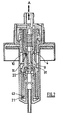
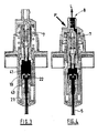
- the pump 1 comprises a pump body 2 and a dispensing head 3 that can be moved manually on the pump body 2, between a rest position ( figure 1 ) and a low position ( figure 2 ).
- the dispensing head 3 comprises a cylinder 4, forming a metering chamber 41, slidably mounted in the pump body 2 and an exhaust valve 9 constituted by a rod slidably mounted inside said cylinder 4.
- the metering chamber 41 is closed in the upper part by the exhaust valve 9, and communicates in the lower part with a liquid intake tube 5 via an intake valve 6.
- the dispensing head 3 further comprises a pusher tip 18 fitted on the upper part of the cylinder 4.
- the pusher tip 18 comprises two concentric skirts 14, 15, a first skirt 14, called an inner skirt, surrounding the cylinder 4, and a second skirt 15, said outer skirt, arranged spaced from the first skirt 14.
- the pusher tip 18 is provided with an orifice 8 through which is ejected, outside the pump, the air contained in the metering chamber during the priming phase or the dose of product to be dispensed. To do this, the passage of the fluid from the metering chamber 41 to the orifice 8 takes place through a channel 7.
- the channel 7 is formed between the outer wall of the cylinder 4 and the inner wall of the first skirt 14.
- the dispensing head 3 further comprises means for sealing the channel 7, preventing the passage of the fluid (air or liquid product to be dispensed) from the metering chamber 41 to the delivery orifice 8 of the dispensing head.
- the closure means consist of a shoulder 10 formed on the outer wall of the rod adapted to bear on a sealing seat 11, of complementary shape, formed in the cylinder 4.
- the sealing of the channel 7 is achieved by maintaining the shoulder 10 of the rod on the sealing seat 11 of the cylinder 4, its opening being effected by spacing the sealing seat 11 from the cylinder 4 opposite the shoulder 10.
- the bearing support of the shoulder 10 of the rod on the sealing seat 11 of the cylinder 4 is formed by a resilient biasing means 12 of the spring type. This is housed in a compartment 42 defined by the cylinder 4 and the upper end of the rod. The spring 12 is mounted in compression in the compartment 42.
- the compartment 42 is isolated from the latter by sealing means 92.
- the means of sealing 92 consists of a radial lip 92 formed on the upper end of the outer wall of the rod.
- the exhaust valve 9 is arranged in the cylinder 4 so as to have, when it is held against the sealing seat of the cylinder 4, in the rest position, a low end 91 extending into the chamber of dosage 41.
- the dispensing head 3 comprises a duct 13 intended to evacuate the air contained in the compartment 42 during the manual movement of the dispensing head 3 on the pump body 2 as well as to allow the tightness of the means to be checked. closure 92 during industrial assembly.
- the duct 13 extends above the compartment 42.
- the pump is provided with a second resilient biasing means 16, of the spring type, intended to ensure the elastic return of the dispensing head 3 in the rest position.
- the spring 16 is advantageously housed between the inner skirt 14 and the outer skirt 15 of the push button 18.
- the intake valve 6 consists of a deformable membrane 19 formed in the lower part of the pump body 2.
- the membrane 19 rests on a tubular support 20 rising in the lower part of the pump body 2.
- the lower end of the support 20 is provided with an external radial extension 21.
- the extension 21 has the role of abutting the cylinder 4 moving axially in the pump body 2, the abutment of said cylinder 4 corresponding to the lower position of the pump 1.
- the upper end of the support 20 is provided with a contact pad 22.
- the membrane 19, comprising an orifice 23, covers the upper end of the support 20, the orifice 23 being disposed opposite the contact stud. contact 22.
- the contact pad 22 In addition to the function of closing the orifice 23 of the membrane 19, the contact pad 22 also has the function of abutting the exhaust valve 9 for the purpose of priming the pump.
- the support 20 is fitted on the outside of a hollow cylindrical portion 24 of the pump body 2, which cylindrical portion 24 extends inside said pump body 2 and opens on the lower part thereof.
- the tube of intake 5 of the liquid product contained in the dispenser is fitted through the inside of the cylindrical portion 24 of the pump body 2.
- the pump further comprises support and fixing means 17 to allow its attachment to a dispenser containing the liquid or semi-liquid product to be dispensed.
- the operating principle of this phase is the following: under the action of a manual pressure P (illustrated by an arrow on the figure 1 ) on the push button 18 of the dispensing head 3, the cylinder 4 - exhaust valve 9 slides axially in the pump body 2 towards the inlet valve 6. The air, trapped in the chamber of dosage 41 sealed in the upper part by the exhaust valve 9 resting on the sealing seat 11 of the cylinder 4 and in the lower part by the inlet valve 6, is then compressed. The cylinder assembly 4 - exhaust valve 9 continues its stroke until the lower end 91 of the exhaust valve 9 comes into abutment against the contact pad 22 of the membrane support 20. The valve 9 thus maintained in standstill, the cylinder 4 continues its stroke alone until its lower end 43 reaches the extension 21 of the membrane support 20. The dispensing head 3 is then in the low position (or end of stroke position) ( figure 2 ).
- the pressure P exerted on the push button 18 of the dispensing head 3 is released.
- the push button 18 rises to its rest position, driving with it the raising of the cylinder 4 by sliding in the pump body 2.
- the sealing seat 11 of the cylinder 4 again comes into contact with the shoulder 10 of the exhaust valve 9, the cylinder 4 driving in its stroke said valve.
- the sealing of the metering chamber 41 is then again ensured by means of the spring 12, the latter pushing the exhaust valve 9 against the sealing seat 11 of the cylinder 4.
- the rise of the dispensing head 3 continues, a vacuum is created in the metering chamber 41 sealed in its upper part.
- the depression created in the metering chamber 41 is greater than the force maintaining the seal of the membrane 19 on the contact pad 22 of the membrane support 20, the membrane 19 deforms and the liquid product contained in the distributor is sucked from the distributor tank to the metering chamber 41 by the tube 5 for taking liquid.
- the dispensing head 3 reaches the rest position, the depression in the metering chamber 41 ceases and the diaphragm 19 returns to the sealed position on the contact pad 22 of the membrane support 20.
- the priming phase is completed when the air contained in the metering chamber is entirely replaced by the product to be delivered.
- the product contained in the metering chamber 41 then corresponds to a dose of product to be delivered.
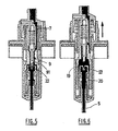
- the liquid phase is illustrated on the Figures 3 to 6 .
- the seal broken, the product contained in the metering chamber 41 can then pass into the channel 7 open to be expelled from the pump 1 through the orifice 8 ( figure 4 ).
- the low position of the dispensing head 3 then corresponds to the complete delivery of the dose of product contained in the metering chamber 41 ( figure 5 ).
- the pressure P exerted on the push button 18 of the dispensing head 3 is released.
- the push button 18 rises to its rest position under the action of the spring 16, causing with it the upward sliding of the cylinder 4 in the pump body 2.
- the seat 11 of the cylinder 4 again comes into contact with the shoulder 10 of the exhaust valve 9, the cylinder then driving in its stroke the exhaust valve 9.
- the sealing of the metering chamber 41 is then at again ensured by the spring 12, the latter pushing the exhaust valve 9 against the sealing seat 11 of the cylinder 4.
- the membrane 19 deforms and the product contained in the distributor is sucked from the dispenser reservoir to the metering chamber 41 through the liquid-collecting tube 5 ( figure 6 ).
- the dispensing head 3 reaches its rest position, the depression in the metering chamber 41 ceases.
- the membrane 19 then returns in a sealed position on the pad 22 of the membrane support 20 ( figure 3 ).
Landscapes
- Containers And Packaging Bodies Having A Special Means To Remove Contents (AREA)
- Closures For Containers (AREA)
- Moulds For Moulding Plastics Or The Like (AREA)
Applications Claiming Priority (1)
| Application Number | Priority Date | Filing Date | Title |
|---|---|---|---|
| FR0755895A FR2917651B1 (fr) | 2007-06-20 | 2007-06-20 | Pompe pour la distribution d'un produit liquide a amorcage ameliore |
Publications (2)
| Publication Number | Publication Date |
|---|---|
| EP2006028A1 true EP2006028A1 (de) | 2008-12-24 |
| EP2006028B1 EP2006028B1 (de) | 2011-09-14 |
Family
ID=38921698
Family Applications (1)
| Application Number | Title | Priority Date | Filing Date |
|---|---|---|---|
| EP08290583A Ceased EP2006028B1 (de) | 2007-06-20 | 2008-06-19 | Pumpe zur Verteilung eines flüssigen Produkts mit verbesserter Zündung |
Country Status (6)
| Country | Link |
|---|---|
| US (2) | US7882988B2 (de) |
| EP (1) | EP2006028B1 (de) |
| JP (1) | JP5303195B2 (de) |
| CN (1) | CN101327473B (de) |
| AT (1) | ATE524241T1 (de) |
| FR (1) | FR2917651B1 (de) |
Cited By (2)
| Publication number | Priority date | Publication date | Assignee | Title |
|---|---|---|---|---|
| WO2017051126A1 (fr) * | 2015-09-22 | 2017-03-30 | Cep Tubes | Systeme de distribution sans air avec pompe |
| CN116999655A (zh) * | 2023-08-04 | 2023-11-07 | 山东威高普瑞医药包装有限公司 | 一种定量注射装置 |
Families Citing this family (17)
| Publication number | Priority date | Publication date | Assignee | Title |
|---|---|---|---|---|
| FR2892158B1 (fr) * | 2005-10-17 | 2011-10-21 | Valois Sas | Pompe de distribution de produit fluide |
| FR2917651B1 (fr) * | 2007-06-20 | 2010-09-17 | Rexam Dispensing Sys | Pompe pour la distribution d'un produit liquide a amorcage ameliore |
| JP5413895B2 (ja) * | 2008-10-31 | 2014-02-12 | 株式会社吉野工業所 | ポンプの押下げヘッド及び押下げヘッド式吐出ポンプ |
| JP4766350B2 (ja) | 2009-01-06 | 2011-09-07 | ソニー株式会社 | ディスク再生装置および方法、プログラム、並びに記録媒体 |
| EP2218515B1 (de) * | 2009-02-06 | 2011-11-23 | Rexam Healthcare La Verpillière | Zerstäuber mit einem Einwegventil |
| IT1397007B1 (it) * | 2009-12-15 | 2012-12-20 | Emsar Spa | Dispenser |
| FR2961191B1 (fr) * | 2010-06-10 | 2012-07-27 | Rexam Healthcare La Verpillier | Pompe pour la delivrance d'un produit, comportant un piston coulissant dans une chambre de dosage |
| EP3881938B1 (de) | 2011-09-20 | 2024-08-07 | Dispensing Technologies B.V. | Abgemessene und aktive spritzvorrichtungen mit aerosolfunktionalität |
| DE202011107265U1 (de) * | 2011-10-31 | 2013-02-11 | Nordson Corporation | Abgabemodul, Auftragskopf und Düsenstock zur Abgabe eines Fluids, insbesondere Heißschmelzklebstoff |
| FR2999960B1 (fr) * | 2012-12-20 | 2015-02-27 | Aptar France Sas | Distributeur de produit fluide rechargeable. |
| JP6356796B2 (ja) * | 2013-07-19 | 2018-07-11 | グラコ ミネソタ インコーポレーテッド | 多点シール潤滑装置 |
| DE102013215599B4 (de) * | 2013-08-07 | 2017-12-07 | Aptar Radolfzell Gmbh | Pumpeinrichtung und Spender für flüssige oder pastöse Medien |
| KR101778578B1 (ko) * | 2016-02-23 | 2017-09-14 | (주)연우 | 사이드버튼이 구비된 펌핑식 화장품 용기 |
| DE102016114456A1 (de) * | 2016-08-04 | 2018-02-08 | Rpc Bramlage Gmbh | Fingerspraypumpe sowie Düsenkopf für eine Sprühpumpe |
| DE102016014898A1 (de) | 2016-12-12 | 2018-06-14 | Aptar Dortmund Gmbh | Pumpe und Abgabevorrichtung |
| WO2019182745A1 (en) | 2018-03-19 | 2019-09-26 | Bryn Pharma, LLC | Epinephrine spray formulations |
| FR3106488B1 (fr) * | 2020-01-27 | 2022-01-21 | Aptar France Sas | Dispositif de distribution de produit pulvérulent |
Citations (3)
| Publication number | Priority date | Publication date | Assignee | Title |
|---|---|---|---|---|
| US5505343A (en) * | 1994-10-19 | 1996-04-09 | Knickerbocker; Michael G. | Manually actuated pump |
| US5655688A (en) * | 1994-10-19 | 1997-08-12 | Aptargroup, Inc. | Atomizing pump with high stroke speed enhancement and valve system therefor |
| WO2006125880A1 (fr) | 2005-05-20 | 2006-11-30 | Rexam Dispensing Systems | Pompe a pointeau pour la distribution de produit liquide |
Family Cites Families (13)
| Publication number | Priority date | Publication date | Assignee | Title |
|---|---|---|---|---|
| JPS55373Y2 (de) * | 1974-09-26 | 1980-01-08 | ||
| US4154374A (en) * | 1977-10-03 | 1979-05-15 | Ethyl Products Company | Finger operated spray pump |
| US4991746A (en) * | 1989-07-07 | 1991-02-12 | Emson Research Inc. | Modular pump having a locking rotatable sleeve |
| FR2652389B1 (fr) * | 1989-09-26 | 1992-12-04 | Debard Andre | Perfectionnement aux pompes a precompression pour la diffusion d'un liquide. |
| FR2686377B1 (fr) * | 1992-01-20 | 1994-03-25 | Valois | Pompe a precompression perfectionnee. |
| IT1272904B (it) * | 1995-01-16 | 1997-07-01 | Elettro Plastica Spa | Pompetta per l'erogazione di liquidi nebulizzati |
| US5720419A (en) * | 1996-03-11 | 1998-02-24 | Calmar Inc. | Pre-compression pump sprayer having improved inlet and discharge valving and an improved pump priming feature |
| US5626264A (en) * | 1996-08-09 | 1997-05-06 | Calmar Inc. | Precompression pump sprayer |
| NL1005189C2 (nl) * | 1997-02-05 | 1998-08-06 | Airspray Int Bv | Afgeefsamenstel voor het afgeven van twee vloeibare componenten. |
| DE10124235B4 (de) * | 2001-05-18 | 2004-08-12 | Esytec Energie- Und Systemtechnik Gmbh | Verfahren und Vorrichtung zur umfassenden Charakterisierung und Kontrolle des Abgases und der Regelung von Motoren, speziell von Verbrennungsmotoren, und von Komponenten der Abgasnachbehandlung |
| US6685062B1 (en) * | 2002-09-16 | 2004-02-03 | Yon Woo Corporation | Dispenser pump |
| FR2862107B1 (fr) * | 2003-11-07 | 2006-02-10 | Valois Sas | Pompe de distribution de produit fluide. |
| FR2917651B1 (fr) * | 2007-06-20 | 2010-09-17 | Rexam Dispensing Sys | Pompe pour la distribution d'un produit liquide a amorcage ameliore |
-
2007
- 2007-06-20 FR FR0755895A patent/FR2917651B1/fr not_active Expired - Fee Related
-
2008
- 2008-06-05 JP JP2008148641A patent/JP5303195B2/ja not_active Expired - Fee Related
- 2008-06-17 CN CN200810109791.6A patent/CN101327473B/zh not_active Expired - Fee Related
- 2008-06-19 EP EP08290583A patent/EP2006028B1/de not_active Ceased
- 2008-06-19 AT AT08290583T patent/ATE524241T1/de not_active IP Right Cessation
- 2008-06-20 US US12/143,461 patent/US7882988B2/en not_active Expired - Fee Related
-
2011
- 2011-01-25 US US13/013,462 patent/US8365966B2/en not_active Expired - Fee Related
Patent Citations (3)
| Publication number | Priority date | Publication date | Assignee | Title |
|---|---|---|---|---|
| US5505343A (en) * | 1994-10-19 | 1996-04-09 | Knickerbocker; Michael G. | Manually actuated pump |
| US5655688A (en) * | 1994-10-19 | 1997-08-12 | Aptargroup, Inc. | Atomizing pump with high stroke speed enhancement and valve system therefor |
| WO2006125880A1 (fr) | 2005-05-20 | 2006-11-30 | Rexam Dispensing Systems | Pompe a pointeau pour la distribution de produit liquide |
Cited By (2)
| Publication number | Priority date | Publication date | Assignee | Title |
|---|---|---|---|---|
| WO2017051126A1 (fr) * | 2015-09-22 | 2017-03-30 | Cep Tubes | Systeme de distribution sans air avec pompe |
| CN116999655A (zh) * | 2023-08-04 | 2023-11-07 | 山东威高普瑞医药包装有限公司 | 一种定量注射装置 |
Also Published As
| Publication number | Publication date |
|---|---|
| CN101327473A (zh) | 2008-12-24 |
| US7882988B2 (en) | 2011-02-08 |
| US8365966B2 (en) | 2013-02-05 |
| FR2917651A1 (fr) | 2008-12-26 |
| CN101327473B (zh) | 2013-05-01 |
| JP2009000516A (ja) | 2009-01-08 |
| US20090020565A1 (en) | 2009-01-22 |
| JP5303195B2 (ja) | 2013-10-02 |
| ATE524241T1 (de) | 2011-09-15 |
| US20110114674A1 (en) | 2011-05-19 |
| FR2917651B1 (fr) | 2010-09-17 |
| EP2006028B1 (de) | 2011-09-14 |
Similar Documents
| Publication | Publication Date | Title |
|---|---|---|
| EP2006028B1 (de) | Pumpe zur Verteilung eines flüssigen Produkts mit verbesserter Zündung | |
| EP1284827B1 (de) | Membranpumpe | |
| EP0623060B1 (de) | Vordruckpumpe | |
| FR2943324A1 (fr) | Dispositif de distribution d'un produit liquide a pateux par pompe de dosage a faible volume mort | |
| EP1588775B1 (de) | Verpackungs- und Abgabeeinheit eines Produktes, insbesondere eines kosmetischen Produktes | |
| EP0928635A1 (de) | Vorrichtung zur Aufnahme und zum Abgeben von Material mit einem luftfrei befüllten Behälter und Verfahren zur ihrer Herstellung | |
| EP1974830B1 (de) | Spritzdüse, die eine axial eingehängte Abschlusshülse umfasst | |
| WO2014096722A1 (fr) | Distributeur de produit fluide rechargeable | |
| EP2279798A1 (de) | Druckknopf für ein Verteilungssystem eines unter Druck stehenden Produkts | |
| CA2163483C (fr) | Pompe manuelle a precompression pour la pulverisation d'un liquide et ensemble de distribution equipe d'une telle pompe | |
| EP1205255B1 (de) | Pumpe zur Abgabe eines Produktes, insbesondere eines kosmetischen Mittels oder eines Pflegemittels | |
| FR2692569A1 (fr) | Procédé et dispositif de remplissage d'un distributeur doseur de substance fluide. | |
| EP1606192B1 (de) | Abgabevorrichtung mit einer druckbetätigbaren pumpe | |
| WO2006125880A1 (fr) | Pompe a pointeau pour la distribution de produit liquide | |
| EP2218515B1 (de) | Zerstäuber mit einem Einwegventil | |
| EP0544549B1 (de) | Pumpe zur Förderung von einem flüssigen oder pastösen Produkt, und Ausgabebehälter mit einer solchen Pumpe | |
| EP1753542B1 (de) | Vereinfachte luftlose spenderpumpe für flüssigprodukte | |
| EP2178649B1 (de) | Ausgabeelement für ein flüssigprodukt | |
| EP1616632B1 (de) | Pumpe zum Ausbringen eines Produkts in verschiedenen Sprühpositionen und entsprechender Behälter | |
| EP1945373B1 (de) | Pumpe mit schwenkklappe | |
| EP1960117B1 (de) | Pumpe mit einer gleitenden buchse | |
| FR3100724A1 (fr) | Pompe à précompression haute pression | |
| FR3083997A1 (fr) | Pompe de distribution d'un produit fluide, tete de distribution equipee d'une telle pompe et flacon associe | |
| FR3080100A1 (fr) | Pompe de distribution de produit fluidique pour flacon de faible hauteur |
Legal Events
| Date | Code | Title | Description |
|---|---|---|---|
| PUAI | Public reference made under article 153(3) epc to a published international application that has entered the european phase |
Free format text: ORIGINAL CODE: 0009012 |
|
| AK | Designated contracting states |
Kind code of ref document: A1 Designated state(s): AT BE BG CH CY CZ DE DK EE ES FI FR GB GR HR HU IE IS IT LI LT LU LV MC MT NL NO PL PT RO SE SI SK TR |
|
| AX | Request for extension of the european patent |
Extension state: AL BA MK RS |
|
| 17P | Request for examination filed |
Effective date: 20090622 |
|
| 17Q | First examination report despatched |
Effective date: 20090723 |
|
| AKX | Designation fees paid |
Designated state(s): AT BE BG CH CY CZ DE DK EE ES FI FR GB GR HR HU IE IS IT LI LT LU LV MC MT NL NO PL PT RO SE SI SK TR |
|
| GRAP | Despatch of communication of intention to grant a patent |
Free format text: ORIGINAL CODE: EPIDOSNIGR1 |
|
| GRAS | Grant fee paid |
Free format text: ORIGINAL CODE: EPIDOSNIGR3 |
|
| GRAA | (expected) grant |
Free format text: ORIGINAL CODE: 0009210 |
|
| AK | Designated contracting states |
Kind code of ref document: B1 Designated state(s): AT BE BG CH CY CZ DE DK EE ES FI FR GB GR HR HU IE IS IT LI LT LU LV MC MT NL NO PL PT RO SE SI SK TR |
|
| REG | Reference to a national code |
Ref country code: GB Ref legal event code: FG4D Free format text: NOT ENGLISH |
|
| REG | Reference to a national code |
Ref country code: CH Ref legal event code: EP |
|
| REG | Reference to a national code |
Ref country code: IE Ref legal event code: FG4D Free format text: LANGUAGE OF EP DOCUMENT: FRENCH |
|
| REG | Reference to a national code |
Ref country code: DE Ref legal event code: R096 Ref document number: 602008009764 Country of ref document: DE Effective date: 20111208 |
|
| REG | Reference to a national code |
Ref country code: NL Ref legal event code: VDEP Effective date: 20110914 |
|
| PG25 | Lapsed in a contracting state [announced via postgrant information from national office to epo] |
Ref country code: NO Free format text: LAPSE BECAUSE OF FAILURE TO SUBMIT A TRANSLATION OF THE DESCRIPTION OR TO PAY THE FEE WITHIN THE PRESCRIBED TIME-LIMIT Effective date: 20111214 Ref country code: HR Free format text: LAPSE BECAUSE OF FAILURE TO SUBMIT A TRANSLATION OF THE DESCRIPTION OR TO PAY THE FEE WITHIN THE PRESCRIBED TIME-LIMIT Effective date: 20110914 Ref country code: FI Free format text: LAPSE BECAUSE OF FAILURE TO SUBMIT A TRANSLATION OF THE DESCRIPTION OR TO PAY THE FEE WITHIN THE PRESCRIBED TIME-LIMIT Effective date: 20110914 Ref country code: LT Free format text: LAPSE BECAUSE OF FAILURE TO SUBMIT A TRANSLATION OF THE DESCRIPTION OR TO PAY THE FEE WITHIN THE PRESCRIBED TIME-LIMIT Effective date: 20110914 Ref country code: SE Free format text: LAPSE BECAUSE OF FAILURE TO SUBMIT A TRANSLATION OF THE DESCRIPTION OR TO PAY THE FEE WITHIN THE PRESCRIBED TIME-LIMIT Effective date: 20110914 |
|
| LTIE | Lt: invalidation of european patent or patent extension |
Effective date: 20110914 |
|
| PG25 | Lapsed in a contracting state [announced via postgrant information from national office to epo] |
Ref country code: SI Free format text: LAPSE BECAUSE OF FAILURE TO SUBMIT A TRANSLATION OF THE DESCRIPTION OR TO PAY THE FEE WITHIN THE PRESCRIBED TIME-LIMIT Effective date: 20110914 Ref country code: GR Free format text: LAPSE BECAUSE OF FAILURE TO SUBMIT A TRANSLATION OF THE DESCRIPTION OR TO PAY THE FEE WITHIN THE PRESCRIBED TIME-LIMIT Effective date: 20111215 Ref country code: LV Free format text: LAPSE BECAUSE OF FAILURE TO SUBMIT A TRANSLATION OF THE DESCRIPTION OR TO PAY THE FEE WITHIN THE PRESCRIBED TIME-LIMIT Effective date: 20110914 Ref country code: AT Free format text: LAPSE BECAUSE OF FAILURE TO SUBMIT A TRANSLATION OF THE DESCRIPTION OR TO PAY THE FEE WITHIN THE PRESCRIBED TIME-LIMIT Effective date: 20110914 Ref country code: CY Free format text: LAPSE BECAUSE OF FAILURE TO SUBMIT A TRANSLATION OF THE DESCRIPTION OR TO PAY THE FEE WITHIN THE PRESCRIBED TIME-LIMIT Effective date: 20110914 |
|
| REG | Reference to a national code |
Ref country code: AT Ref legal event code: MK05 Ref document number: 524241 Country of ref document: AT Kind code of ref document: T Effective date: 20110914 |
|
| REG | Reference to a national code |
Ref country code: IE Ref legal event code: FD4D |
|
| PG25 | Lapsed in a contracting state [announced via postgrant information from national office to epo] |
Ref country code: SK Free format text: LAPSE BECAUSE OF FAILURE TO SUBMIT A TRANSLATION OF THE DESCRIPTION OR TO PAY THE FEE WITHIN THE PRESCRIBED TIME-LIMIT Effective date: 20110914 Ref country code: IS Free format text: LAPSE BECAUSE OF FAILURE TO SUBMIT A TRANSLATION OF THE DESCRIPTION OR TO PAY THE FEE WITHIN THE PRESCRIBED TIME-LIMIT Effective date: 20120114 Ref country code: CZ Free format text: LAPSE BECAUSE OF FAILURE TO SUBMIT A TRANSLATION OF THE DESCRIPTION OR TO PAY THE FEE WITHIN THE PRESCRIBED TIME-LIMIT Effective date: 20110914 Ref country code: IE Free format text: LAPSE BECAUSE OF FAILURE TO SUBMIT A TRANSLATION OF THE DESCRIPTION OR TO PAY THE FEE WITHIN THE PRESCRIBED TIME-LIMIT Effective date: 20110914 |
|
| PG25 | Lapsed in a contracting state [announced via postgrant information from national office to epo] |
Ref country code: PL Free format text: LAPSE BECAUSE OF FAILURE TO SUBMIT A TRANSLATION OF THE DESCRIPTION OR TO PAY THE FEE WITHIN THE PRESCRIBED TIME-LIMIT Effective date: 20110914 Ref country code: NL Free format text: LAPSE BECAUSE OF FAILURE TO SUBMIT A TRANSLATION OF THE DESCRIPTION OR TO PAY THE FEE WITHIN THE PRESCRIBED TIME-LIMIT Effective date: 20110914 Ref country code: EE Free format text: LAPSE BECAUSE OF FAILURE TO SUBMIT A TRANSLATION OF THE DESCRIPTION OR TO PAY THE FEE WITHIN THE PRESCRIBED TIME-LIMIT Effective date: 20110914 Ref country code: IT Free format text: LAPSE BECAUSE OF FAILURE TO SUBMIT A TRANSLATION OF THE DESCRIPTION OR TO PAY THE FEE WITHIN THE PRESCRIBED TIME-LIMIT Effective date: 20110914 Ref country code: PT Free format text: LAPSE BECAUSE OF FAILURE TO SUBMIT A TRANSLATION OF THE DESCRIPTION OR TO PAY THE FEE WITHIN THE PRESCRIBED TIME-LIMIT Effective date: 20120116 Ref country code: RO Free format text: LAPSE BECAUSE OF FAILURE TO SUBMIT A TRANSLATION OF THE DESCRIPTION OR TO PAY THE FEE WITHIN THE PRESCRIBED TIME-LIMIT Effective date: 20110914 |
|
| PLBE | No opposition filed within time limit |
Free format text: ORIGINAL CODE: 0009261 |
|
| STAA | Information on the status of an ep patent application or granted ep patent |
Free format text: STATUS: NO OPPOSITION FILED WITHIN TIME LIMIT |
|
| PG25 | Lapsed in a contracting state [announced via postgrant information from national office to epo] |
Ref country code: DK Free format text: LAPSE BECAUSE OF FAILURE TO SUBMIT A TRANSLATION OF THE DESCRIPTION OR TO PAY THE FEE WITHIN THE PRESCRIBED TIME-LIMIT Effective date: 20110914 |
|
| 26N | No opposition filed |
Effective date: 20120615 |
|
| REG | Reference to a national code |
Ref country code: DE Ref legal event code: R097 Ref document number: 602008009764 Country of ref document: DE Effective date: 20120615 |
|
| BERE | Be: lapsed |
Owner name: REXAM DISPENSING SYSTEMS Effective date: 20120630 |
|
| PG25 | Lapsed in a contracting state [announced via postgrant information from national office to epo] |
Ref country code: MC Free format text: LAPSE BECAUSE OF NON-PAYMENT OF DUE FEES Effective date: 20120630 |
|
| REG | Reference to a national code |
Ref country code: CH Ref legal event code: PL |
|
| REG | Reference to a national code |
Ref country code: CH Ref legal event code: PL |
|
| PG25 | Lapsed in a contracting state [announced via postgrant information from national office to epo] |
Ref country code: ES Free format text: LAPSE BECAUSE OF FAILURE TO SUBMIT A TRANSLATION OF THE DESCRIPTION OR TO PAY THE FEE WITHIN THE PRESCRIBED TIME-LIMIT Effective date: 20111225 Ref country code: CH Free format text: LAPSE BECAUSE OF NON-PAYMENT OF DUE FEES Effective date: 20120630 Ref country code: LI Free format text: LAPSE BECAUSE OF NON-PAYMENT OF DUE FEES Effective date: 20120630 Ref country code: BE Free format text: LAPSE BECAUSE OF NON-PAYMENT OF DUE FEES Effective date: 20120630 |
|
| PG25 | Lapsed in a contracting state [announced via postgrant information from national office to epo] |
Ref country code: BG Free format text: LAPSE BECAUSE OF FAILURE TO SUBMIT A TRANSLATION OF THE DESCRIPTION OR TO PAY THE FEE WITHIN THE PRESCRIBED TIME-LIMIT Effective date: 20111214 |
|
| PG25 | Lapsed in a contracting state [announced via postgrant information from national office to epo] |
Ref country code: MT Free format text: LAPSE BECAUSE OF FAILURE TO SUBMIT A TRANSLATION OF THE DESCRIPTION OR TO PAY THE FEE WITHIN THE PRESCRIBED TIME-LIMIT Effective date: 20110914 |
|
| PG25 | Lapsed in a contracting state [announced via postgrant information from national office to epo] |
Ref country code: TR Free format text: LAPSE BECAUSE OF FAILURE TO SUBMIT A TRANSLATION OF THE DESCRIPTION OR TO PAY THE FEE WITHIN THE PRESCRIBED TIME-LIMIT Effective date: 20110914 |
|
| PG25 | Lapsed in a contracting state [announced via postgrant information from national office to epo] |
Ref country code: LU Free format text: LAPSE BECAUSE OF NON-PAYMENT OF DUE FEES Effective date: 20120619 |
|
| PG25 | Lapsed in a contracting state [announced via postgrant information from national office to epo] |
Ref country code: HU Free format text: LAPSE BECAUSE OF FAILURE TO SUBMIT A TRANSLATION OF THE DESCRIPTION OR TO PAY THE FEE WITHIN THE PRESCRIBED TIME-LIMIT Effective date: 20080619 |
|
| REG | Reference to a national code |
Ref country code: FR Ref legal event code: PLFP Year of fee payment: 9 |
|
| REG | Reference to a national code |
Ref country code: FR Ref legal event code: CA Effective date: 20170410 Ref country code: FR Ref legal event code: CD Owner name: NEMERA LE TREPORT, FR Effective date: 20170410 Ref country code: FR Ref legal event code: TP Owner name: NEMERA LE TREPORT, FR Effective date: 20170410 |
|
| REG | Reference to a national code |
Ref country code: FR Ref legal event code: PLFP Year of fee payment: 10 |
|
| REG | Reference to a national code |
Ref country code: GB Ref legal event code: 732E Free format text: REGISTERED BETWEEN 20170615 AND 20170621 |
|
| REG | Reference to a national code |
Ref country code: DE Ref legal event code: R082 Ref document number: 602008009764 Country of ref document: DE Representative=s name: GRUENECKER PATENT- UND RECHTSANWAELTE PARTG MB, DE Ref country code: DE Ref legal event code: R082 Ref document number: 602008009764 Country of ref document: DE Representative=s name: MAIWALD PATENTANWALTSGESELLSCHAFT MBH, DE Ref country code: DE Ref legal event code: R082 Ref document number: 602008009764 Country of ref document: DE Representative=s name: MAIWALD PATENTANWALTS- UND RECHTSANWALTSGESELL, DE |
|
| REG | Reference to a national code |
Ref country code: DE Ref legal event code: R082 Ref document number: 602008009764 Country of ref document: DE Representative=s name: MAIWALD GMBH, DE Ref country code: DE Ref legal event code: R082 Ref document number: 602008009764 Country of ref document: DE Representative=s name: MAIWALD PATENTANWALTSGESELLSCHAFT MBH, DE Ref country code: DE Ref legal event code: R081 Ref document number: 602008009764 Country of ref document: DE Owner name: NEMERA LE TREPORT, FR Free format text: FORMER OWNER: REXAM DISPENSING SYSTEMS, LE TREPORT, FR Ref country code: DE Ref legal event code: R082 Ref document number: 602008009764 Country of ref document: DE Representative=s name: MAIWALD PATENTANWALTS- UND RECHTSANWALTSGESELL, DE |
|
| REG | Reference to a national code |
Ref country code: FR Ref legal event code: PLFP Year of fee payment: 11 |
|
| PGFP | Annual fee paid to national office [announced via postgrant information from national office to epo] |
Ref country code: FR Payment date: 20230629 Year of fee payment: 16 Ref country code: DE Payment date: 20230620 Year of fee payment: 16 |
|
| PGFP | Annual fee paid to national office [announced via postgrant information from national office to epo] |
Ref country code: GB Payment date: 20230620 Year of fee payment: 16 |
|
| REG | Reference to a national code |
Ref country code: DE Ref legal event code: R119 Ref document number: 602008009764 Country of ref document: DE |
|
| GBPC | Gb: european patent ceased through non-payment of renewal fee |
Effective date: 20240619 |
|
| PG25 | Lapsed in a contracting state [announced via postgrant information from national office to epo] |
Ref country code: DE Free format text: LAPSE BECAUSE OF NON-PAYMENT OF DUE FEES Effective date: 20250101 |
|
| PG25 | Lapsed in a contracting state [announced via postgrant information from national office to epo] |
Ref country code: FR Free format text: LAPSE BECAUSE OF NON-PAYMENT OF DUE FEES Effective date: 20240630 |
|
| PG25 | Lapsed in a contracting state [announced via postgrant information from national office to epo] |
Ref country code: GB Free format text: LAPSE BECAUSE OF NON-PAYMENT OF DUE FEES Effective date: 20240619 |