EP2006055A1 - Entraînement d'articulation de manipulateur de robot avec support de couple - Google Patents
Entraînement d'articulation de manipulateur de robot avec support de couple Download PDFInfo
- Publication number
- EP2006055A1 EP2006055A1 EP08158660A EP08158660A EP2006055A1 EP 2006055 A1 EP2006055 A1 EP 2006055A1 EP 08158660 A EP08158660 A EP 08158660A EP 08158660 A EP08158660 A EP 08158660A EP 2006055 A1 EP2006055 A1 EP 2006055A1
- Authority
- EP
- European Patent Office
- Prior art keywords
- cam
- lever
- drive according
- joint drive
- robot
- Prior art date
- Legal status (The legal status is an assumption and is not a legal conclusion. Google has not performed a legal analysis and makes no representation as to the accuracy of the status listed.)
- Granted
Links
Images



Classifications
-
- B—PERFORMING OPERATIONS; TRANSPORTING
- B25—HAND TOOLS; PORTABLE POWER-DRIVEN TOOLS; MANIPULATORS
- B25J—MANIPULATORS; CHAMBERS PROVIDED WITH MANIPULATION DEVICES
- B25J9/00—Program-controlled manipulators
- B25J9/10—Program-controlled manipulators characterised by positioning means for manipulator elements
- B25J9/102—Gears specially adapted therefor, e.g. reduction gears
- B25J9/1025—Harmonic drives
-
- B—PERFORMING OPERATIONS; TRANSPORTING
- B25—HAND TOOLS; PORTABLE POWER-DRIVEN TOOLS; MANIPULATORS
- B25J—MANIPULATORS; CHAMBERS PROVIDED WITH MANIPULATION DEVICES
- B25J19/00—Accessories fitted to manipulators, e.g. for monitoring, for viewing; Safety devices combined with or specially adapted for use in connection with manipulators
- B25J19/0091—Shock absorbers
-
- B—PERFORMING OPERATIONS; TRANSPORTING
- B25—HAND TOOLS; PORTABLE POWER-DRIVEN TOOLS; MANIPULATORS
- B25J—MANIPULATORS; CHAMBERS PROVIDED WITH MANIPULATION DEVICES
- B25J19/00—Accessories fitted to manipulators, e.g. for monitoring, for viewing; Safety devices combined with or specially adapted for use in connection with manipulators
- B25J19/06—Safety devices
- B25J19/063—Safety devices working only upon contact with an outside object
-
- B—PERFORMING OPERATIONS; TRANSPORTING
- B25—HAND TOOLS; PORTABLE POWER-DRIVEN TOOLS; MANIPULATORS
- B25J—MANIPULATORS; CHAMBERS PROVIDED WITH MANIPULATION DEVICES
- B25J9/00—Program-controlled manipulators
- B25J9/10—Program-controlled manipulators characterised by positioning means for manipulator elements
- B25J9/109—Program-controlled manipulators characterised by positioning means for manipulator elements comprising mechanical programming means, e.g. cams
-
- F—MECHANICAL ENGINEERING; LIGHTING; HEATING; WEAPONS; BLASTING
- F16—ENGINEERING ELEMENTS AND UNITS; GENERAL MEASURES FOR PRODUCING AND MAINTAINING EFFECTIVE FUNCTIONING OF MACHINES OR INSTALLATIONS; THERMAL INSULATION IN GENERAL
- F16F—SPRINGS; SHOCK-ABSORBERS; MEANS FOR DAMPING VIBRATION
- F16F15/00—Suppression of vibrations in systems; Means or arrangements for avoiding or reducing out-of-balance forces, e.g. due to motion
- F16F15/02—Suppression of vibrations of non-rotating, e.g. reciprocating systems; Suppression of vibrations of rotating systems by use of members not moving with the rotating systems
- F16F15/04—Suppression of vibrations of non-rotating, e.g. reciprocating systems; Suppression of vibrations of rotating systems by use of members not moving with the rotating systems using elastic means
- F16F15/043—Suppression of vibrations of non-rotating, e.g. reciprocating systems; Suppression of vibrations of rotating systems by use of members not moving with the rotating systems using elastic means acting on a cam follower
-
- F—MECHANICAL ENGINEERING; LIGHTING; HEATING; WEAPONS; BLASTING
- F16—ENGINEERING ELEMENTS AND UNITS; GENERAL MEASURES FOR PRODUCING AND MAINTAINING EFFECTIVE FUNCTIONING OF MACHINES OR INSTALLATIONS; THERMAL INSULATION IN GENERAL
- F16F—SPRINGS; SHOCK-ABSORBERS; MEANS FOR DAMPING VIBRATION
- F16F15/00—Suppression of vibrations in systems; Means or arrangements for avoiding or reducing out-of-balance forces, e.g. due to motion
- F16F15/10—Suppression of vibrations in rotating systems by making use of members moving with the system
- F16F15/12—Suppression of vibrations in rotating systems by making use of members moving with the system using elastic members or friction-damping members, e.g. between a rotating shaft and a gyratory mass mounted thereon
- F16F15/1204—Suppression of vibrations in rotating systems by making use of members moving with the system using elastic members or friction-damping members, e.g. between a rotating shaft and a gyratory mass mounted thereon with a kinematic mechanism or gear system
- F16F15/1205—Suppression of vibrations in rotating systems by making use of members moving with the system using elastic members or friction-damping members, e.g. between a rotating shaft and a gyratory mass mounted thereon with a kinematic mechanism or gear system with a kinematic mechanism, i.e. linkages, levers
-
- F—MECHANICAL ENGINEERING; LIGHTING; HEATING; WEAPONS; BLASTING
- F16—ENGINEERING ELEMENTS AND UNITS; GENERAL MEASURES FOR PRODUCING AND MAINTAINING EFFECTIVE FUNCTIONING OF MACHINES OR INSTALLATIONS; THERMAL INSULATION IN GENERAL
- F16F—SPRINGS; SHOCK-ABSORBERS; MEANS FOR DAMPING VIBRATION
- F16F15/00—Suppression of vibrations in systems; Means or arrangements for avoiding or reducing out-of-balance forces, e.g. due to motion
- F16F15/10—Suppression of vibrations in rotating systems by making use of members moving with the system
- F16F15/12—Suppression of vibrations in rotating systems by making use of members moving with the system using elastic members or friction-damping members, e.g. between a rotating shaft and a gyratory mass mounted thereon
- F16F15/121—Suppression of vibrations in rotating systems by making use of members moving with the system using elastic members or friction-damping members, e.g. between a rotating shaft and a gyratory mass mounted thereon using springs as elastic members, e.g. metallic springs
- F16F15/123—Wound springs
Definitions
- the invention relates to a joint drive for a robot manipulator.
- a joint drive for a robot manipulator is presently the drive for any joint or any axis of a robot manipulator to understand that connects two manipulator elements hinged together and adjusts the angle of the elements to each other.
- Manipulator elements are presently the arm elements of the manipulator arm and the manipulator base.
- rigid drives are generally used as joint drives, i. the output is directly and unsprung, possibly stocky via a drive gear, connected to the drive motor.
- non-rigid articulating drives are desirable in certain applications, for example, to reduce the risk of injury and damage in collisions of the manipulator arm with persons or objects.
- a non-rigid joint drive is further achieved that external forces acting on the manipulator forces are not rigidly introduced into the joint drive, whereby the risk of damage to the joint drive is reduced.
- Humanoid robots and bionics also use non-rigid joint drives that, like the human muscle, can temporarily store kinetic energy during dynamic movements.
- the efficiency, the power density and the integration density are unsatisfactory.
- the restoring torque of the torque arms of conventional manipulator arm-type joint drives is so low in practice that they must be able to act dynamically for a manipulator arm with a plurality of joints, which may have to bear the dead weight of one or more manipulator arm elements, and must have sufficient positioning accuracy are.
- the object of the invention is in contrast to provide a robot manipulator joint drive with high power density and adjustable progressive torque arm.
- the manipulator arm joint drive has a drive motor, a drive gear driven by the drive motor, and a drive shaft, wherein the drive gear has a spring-loaded suspension support.
- the torque arm is formed by a rotatable cam and at least one prestressed with a lever spring cam lever, which runs on the cam. When the cam disc is deflected from the neutral position, the cam lever generates a restoring moment and resiliently limits the rotation of the cam disc.
- the Mgzier is created to design the suspension of the torque arm progressively, by an appropriate design of the cam track of the cam. In this way, it is possible, for example, to realize already at small deflections of the torque arm from the neutral position already relatively high restoring forces.
- an appropriate Design of the cam track can be adjusted in a wide range, the Progession the restoring force against the deflection.
- the spring force of the lever spring can be translated many times. In this way, high restoring forces of the torque arm can be realized in a very small space.
- the cam is preferably in a plane parallel to the rotating elements of the drive gear and more preferably the axial of the cam is identical to the axial of the drive motor and / or the drive gear. This allows a high energy density and a compact design.
- Torque support is understood to mean, in particular, an element whose task is to capture a differential torque, for example between a drive and an output, and in particular its introduction into a support structure or a solid structure, such as a housing or a frame.
- At least one of the cam levers is adjustable, ie the fixed or quasi-stationary articulation point of the cam lever is adjustable, so that the cam lever can be moved or pivoted as a whole in relation to the cam lever of the second direction.
- the rigidity of the torque arm during operation of the manipulator arm is adjustable.
- the adjustable cam lever is adjusted relative to the counteracting cam lever, that the spring force of the restoring lever spring is translated by shifting the working point on the cam high and / or the lever spring is biased stronger.
- the cam lever can be adjusted relative to the counteracting cam lever such that the joint drive is designed soft.
- a cam lever actuator is provided, with which the adjustable cam lever can be adjusted.
- the actuator is preferably a compact electric motor, which has a high-gearbox, such as a sliding wedge. In this way, the rigidity of the torque arm can be adjusted at any time within a very short time and adapted to the particular situation during operation of the robot.
- the cam lever on a cam wheel, which runs on the cam.
- the friction between the cam lever and the cam is reduced to a minimum, so that the sprung torque arm shows virtually no hysteresis.
- the single curved path of the cam is from the axis near the cam out radially outward.
- different characteristics of the torque arm suspension can be adjusted. If the cam lever is in the radially inner region of the curved path, relatively low restoring forces are generated with a small progression, so that the lever spring experiences only a small change in length when deflected.
- relatively high restoring forces are generated, since even slight deflection changes result in large changes in the length of the lifting spring.
- the cam has two mutually mirror-symmetrical but not necessarily identical double cam tracks, which are each associated with both the one and the other direction of rotation.
- the cam disk has two or more point-symmetrical individual cam tracks which act in the same direction of rotation with approximately the same forces in cooperation with the respectively associated cam lift.
- a separate cam lever is arranged in each case.
- the restoring force can be doubled in a confined space.
- the lever spring braces the two directionally acting cam lever directly to each other.
- the cam levers are thus not biased to the stationary housing, but are clamped together directly by the spring element.
- the actuator acts on two directionally acting cam lever.
- two directionally acting stationary cam levers on two single cam tracks and two directionally acting adjustable cam lever on two other single cam tracks are provided. Both the two fixed cam levers and the two adjustable cam levers can each be clamped together directly by a single lever spring.
- the actuator has a control gear, which is designed as Gleitkeilgetriebe.
- the drive gear can be formed by a Gleitkeilgetriebe.
- Sliding wedge gears are known under the name "Harmonic Drive” and are very compact. They have high translations from 1:30 to 1: 300. GleitkeilgeInstitute are therefore very suitable for drive gear and actuating gear of a manipulator arm joint drive.
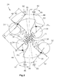
- a robot manipulator arm joint drive 10 is shown, are articulated by the two arm members 12,14 a robot manipulator arm and driven together.
- the robot can be an industrial robot that is used in production.
- the robot may also be another, for example, humanoid robot, wherein the manipulator arm is designed as an arm or leg and performs running movements, throwing movements or other types of movements.
- the manipulator arm-joint drive 10 is essentially divided into a drive motor 16 with a drive gear 18 and a torque arm 20, which in turn is formed by an actuator 22 and a torque arm suspension 24.
- the actuator 22 is in turn formed by a servomotor 23 and a control gear 26.
- the electric drive motor 16 generates a torque that is transmitted by the drive gear 18 highly stocky on the output-side arm member 14, whereby the output-side arm member 14 relative to the drive-side arm member 12 pivots about the axis of rotation.
- the drive gear 18 has no stationary torque support, but has a spring-loaded and adjustable torque arm 20 with a suspension 24. In the Fig. 1 illustrated suspension 24 is not, as shown, in the leaf level, but in a plane parallel to the planes of rotation of the gear 18,26.
- a component of the drive gear 18 is rigidly connected to a rotatable cam 30 whose rotation is always held in an equilibrium position by means of lever springs 3-6,38 biased cam lever 41-44.
- the cam levers 41-44 each have a cam wheel 31-34, whereby the cam levers 41-44 run practically without resistance on the cam 30.
- Two cam levers 41, 42 of the four cam levers 41-44 are articulated in a stationary manner, i. connected by joints 55,56 to the housing 50 of the joint drive 10, which is fixedly connected to the first arm member 12, the drive motor 16 and the actuator 22 is connected.
- the other two cam levers 43, 44 are movably mounted to the housing 50 mounted on a setting ring 60.
- the lever joints 46, 47 can be moved on a circular line 48 whose center is the axis of rotation of the cam disk 30.
- the articulation points 55,56 are on the circle 48.
- the adjustment ring 60 can be rotated in the adjustment of the moment support on which the articulation points forming cam lever joints 46,47 are arranged. In this way, the articulation points of the two adjustable cam lever 43,44 can be adjusted. As a result, the respective equilibrium position of the cam discs 30 can be changed and can be so that adjust the restoring forces in relation to the deflection in a wide range.
- the cam plate 30 has two point-symmetrical and mirror-symmetrical opposite trough-shaped double cam tracks 70, 71, each having two individual cam tracks 70 1 , 70 2 , 71 1 , 71 2 each have a curved, outwardly approximately radial course and in this way together with the respective cam levers 41-44 form end stops.
- Both the drive gear 18 and the actuating gear 26 are each formed as a so-called Gleitkeilgetriebe, also called “Harmonic Drive”.
- the two gears 18,26 each have an inner by the respective motor 16,23 driven rotating shaft 80,80 ', a continuously deformed by the rotating shaft pulley 80,80' flexible external toothed chain 82,82 'and a rigid internal toothed ring 84, 84 ', into which the externally toothed toothed chain 82, 82' engages.
- the shaft plate 80 is the motor side and the outer ring 84 is arranged on the output side.
- the toothed chain 82 is supported on the torque arm and is rotatably connected to the cam 30.
- the wave washer 80 ' is driven by the servomotor 24.
- the outer ring 84 ' is fixedly connected to the joint housing 50.
- the toothed chain 82 ' is rotatably connected to the adjusting ring 60, so adjusted this.
- the restoring moment is created by the spring force of the respective lever spring 36,38, which introduces a moment in the relevant cam lever 41-44 about the respective pivot point 46,47,55,56 on the effective lever R 1 .
- This torque generated via the effective radius R 2 of the cam gears 31-34, a contact force on the cam 30, which in turn multiplied by an effective radius R 3 for half restoring torque of the relevant page.
- the total torque acting from the cam 30 to the outside is composed of the superimposed torques of both double cam tracks 70,71 of the cam 30. Since the characteristics of all individual cam tracks 70 1 , 70 2 , 71 1 , 71 2 of the cam 30th remain the same at different stress states, results in the operation of a simple calculation of the resulting torques.
- the Fig. 4A shows a typical characteristic of the torque arm 20 for a single lever spring 41-44.
- FIGS. 4A and 4B is shown on the ordinate the restoring torque T and on the abscissa the cam disc deflection ⁇ .
- Fig. 4B Two different diagrams of the energy ⁇ E 1 , ⁇ E 2 stored in the lever springs for different settings of the adjusting ring 60 are shown.
Landscapes
- Engineering & Computer Science (AREA)
- Mechanical Engineering (AREA)
- General Engineering & Computer Science (AREA)
- Robotics (AREA)
- Physics & Mathematics (AREA)
- Acoustics & Sound (AREA)
- Aviation & Aerospace Engineering (AREA)
- Manipulator (AREA)
- Transmission Devices (AREA)
Applications Claiming Priority (1)
| Application Number | Priority Date | Filing Date | Title |
|---|---|---|---|
| DE102007028758A DE102007028758B4 (de) | 2007-06-22 | 2007-06-22 | Roboter-Manipulator-Gelenkantrieb |
Publications (2)
| Publication Number | Publication Date |
|---|---|
| EP2006055A1 true EP2006055A1 (fr) | 2008-12-24 |
| EP2006055B1 EP2006055B1 (fr) | 2009-12-30 |
Family
ID=39768675
Family Applications (1)
| Application Number | Title | Priority Date | Filing Date |
|---|---|---|---|
| EP08158660A Active EP2006055B1 (fr) | 2007-06-22 | 2008-06-20 | Entraînement d'articulation de manipulateur de robot avec support de couple |
Country Status (3)
| Country | Link |
|---|---|
| EP (1) | EP2006055B1 (fr) |
| AT (1) | ATE453492T1 (fr) |
| DE (2) | DE102007028758B4 (fr) |
Cited By (5)
| Publication number | Priority date | Publication date | Assignee | Title |
|---|---|---|---|---|
| ITTO20110848A1 (it) * | 2011-09-23 | 2013-03-24 | Fond Istituto Italiano Di Tecnologia | Attuatore rotante elastico. |
| CN107738268A (zh) * | 2017-11-20 | 2018-02-27 | 河北工业大学 | 一种基于杠杆机构的可变刚度柔性关节 |
| CN109465848A (zh) * | 2018-11-30 | 2019-03-15 | 广东工业大学 | 一种基于凸轮式杠杆结构的机器人关节变刚度模块 |
| DE102019125706A1 (de) * | 2019-09-24 | 2021-03-25 | Deutsches Zentrum für Luft- und Raumfahrt e.V. | Drehgelenkeinrichtung für einen Roboter und Roboter |
| CN112888537A (zh) * | 2018-10-22 | 2021-06-01 | 开姆尼茨工业大学 | 弹性关节 |
Families Citing this family (24)
| Publication number | Priority date | Publication date | Assignee | Title |
|---|---|---|---|---|
| DE202010005315U1 (de) | 2010-04-27 | 2011-10-20 | Kuka Systems Gmbh | Applikationseinrichtung |
| DE202010005313U1 (de) | 2010-04-27 | 2011-10-27 | Kuka Laboratories Gmbh | Bearbeitungseinrichtung |
| DE202011050082U1 (de) | 2011-05-10 | 2012-08-13 | Kuka Systems Gmbh | Montageeinrichtung |
| DE102012209243B4 (de) * | 2012-05-31 | 2017-02-23 | Deutsches Zentrum für Luft- und Raumfahrt e.V. | Roboter-Gelenksystem |
| DE202013104264U1 (de) | 2013-09-18 | 2015-01-09 | Daimler Ag | Arbeitsstation |
| DE202013104392U1 (de) | 2013-09-26 | 2015-01-12 | Daimler Ag | Arbeitsvorrichtung |
| DE202013104389U1 (de) | 2013-09-26 | 2015-01-20 | Daimler Ag | Arbeitsvorrichtung |
| DE202013104544U1 (de) | 2013-10-08 | 2015-01-15 | Daimler Ag | Arbeitsvorrichtung |
| DE202013104860U1 (de) | 2013-10-30 | 2015-02-02 | Daimler Ag | Arbeitsvorrichtung |
| DE202013105036U1 (de) | 2013-11-08 | 2015-02-10 | Daimler Ag | Erfassungseinrichtung |
| DE202013105203U1 (de) | 2013-11-18 | 2015-02-19 | Kuka Systems Gmbh | Arbeitsvorrichtung |
| DE202013105501U1 (de) | 2013-12-03 | 2015-03-03 | Daimler Ag | Arbeitsvorrichtung |
| DE202013105504U1 (de) | 2013-12-03 | 2015-03-03 | Daimler Ag | Arbeitsvorrichtung |
| WO2015082485A1 (fr) | 2013-12-03 | 2015-06-11 | Kuka Systems Gmbh | Dispositif de travail et procédé de travail |
| DE202013105677U1 (de) | 2013-12-13 | 2015-03-13 | Kuka Systems Gmbh | Arbeitsvorrichtung |
| DE202013105910U1 (de) | 2013-12-23 | 2015-03-24 | Kuka Systems Gmbh | Roboterwerkzeug |
| DE202014100334U1 (de) | 2014-01-27 | 2015-05-08 | Kuka Systems Gmbh | Roboterwerkzeug |
| DE202014100803U1 (de) | 2014-02-21 | 2015-05-22 | Kuka Systems Gmbh | Messeinrichtung |
| DE202014102559U1 (de) | 2014-06-02 | 2015-09-03 | Kuka Systems Gmbh | Stopfensetzeinrichtung |
| DE202014103132U1 (de) | 2014-07-08 | 2015-10-07 | Kuka Systems Gmbh | Applikationswerkzeug |
| WO2016049006A1 (fr) | 2014-09-22 | 2016-03-31 | Kuka Systems Corporation North America | Appareil robotique et procédé pour l'installation de bagues et d'écrous sur des éléments de fixation |
| DE102016215683B4 (de) | 2016-08-22 | 2024-12-19 | Volkswagen Aktiengesellschaft | Verfahren zur Steuerung einer robotergestützten Bearbeitung eines Werkstückes mittels einer Mensch-Roboter-Kollaboration-Schnittstelle |
| DE102020212696A1 (de) | 2020-10-08 | 2022-04-14 | Robert Bosch Gesellschaft mit beschränkter Haftung | Handhabungsvorrichtung mit adaptivem Kollisionsschutzsystem |
| DE102021000619B3 (de) | 2021-01-26 | 2021-12-30 | Technische Universität Chemnitz | Nichtlineares elastisches Gelenk mit einem elastischen Mechanismus und Antrieben |
Citations (13)
| Publication number | Priority date | Publication date | Assignee | Title |
|---|---|---|---|---|
| BE386289A (fr) * | ||||
| DE585096C (de) * | 1929-04-17 | 1933-09-28 | Viggo Axel Kjaer Dipl Ing | Vorrichtung zum Ausgleichen freier Kraefte und Momente in Maschinenanlagen, insbesondere Brennkraftmaschinen |
| DE597912C (de) * | 1934-06-02 | Robert Bosch Akt Ges | Kolbenstossdaempfer | |
| DE1270332B (de) * | 1965-09-17 | 1968-06-12 | Ibm | Vorrichtung zur Daempfung von Drehschwingungen von ueber eine Schaltkupplung und eine elastische Kupplung intermittierend antreibbaren Wellen |
| JPS57192648A (en) * | 1981-05-25 | 1982-11-26 | Hitachi Ltd | Position repeatable floating mechanism |
| US4725087A (en) * | 1985-03-15 | 1988-02-16 | Mitsubishi Denki Kabushiki Kaisha | Spring-loaded hand for an industrial robot |
| DE3702494A1 (de) * | 1987-01-26 | 1988-08-04 | Mannesmann Ag | Dreh- und schwenkeinheit |
| SU1483132A1 (ru) * | 1987-02-03 | 1989-05-30 | Всесоюзный Научно-Исследовательский Институт Горной Механики Им.М.М.Федорова | Амортизатор с переменной жесткостью |
| WO1989008012A1 (fr) * | 1988-02-23 | 1989-09-08 | S.O.P.A.P. S.A. | Manipulateur mecanique a axes multiples |
| DE10010680A1 (de) * | 2000-03-04 | 2001-09-13 | Oechsler Ag | Wellgetriebe und Innenrad für ein solches Getriebe |
| DE102005016780A1 (de) * | 2004-04-30 | 2005-11-24 | Heidelberger Druckmaschinen Ag | Verfahren zum Antreiben einer drucktechnischen Maschine mit mehreren Teilaggregaten und Vorrichtung zur Durchführung des Verfahrens |
| DE102006040958A1 (de) * | 2006-08-31 | 2008-03-06 | Contitech Vibration Control Gmbh | Steifigkeitsschaltbare Drehmomentstütze |
| DE102007014023A1 (de) * | 2007-03-23 | 2008-09-25 | Deutsches Zentrum für Luft- und Raumfahrt e.V. | Roboter-Manipulatorarm-Gelenkantrieb |
Family Cites Families (2)
| Publication number | Priority date | Publication date | Assignee | Title |
|---|---|---|---|---|
| NO751952L (fr) * | 1975-06-03 | 1976-12-06 | Akers Mek Verksted As | |
| DE29713253U1 (de) * | 1997-07-25 | 1998-11-19 | Beyert, Thomas, 53804 Much | Überlastkupplung |
-
2007
- 2007-06-22 DE DE102007028758A patent/DE102007028758B4/de not_active Expired - Fee Related
-
2008
- 2008-06-20 DE DE502008000282T patent/DE502008000282D1/de active Active
- 2008-06-20 AT AT08158660T patent/ATE453492T1/de active
- 2008-06-20 EP EP08158660A patent/EP2006055B1/fr active Active
Patent Citations (13)
| Publication number | Priority date | Publication date | Assignee | Title |
|---|---|---|---|---|
| BE386289A (fr) * | ||||
| DE597912C (de) * | 1934-06-02 | Robert Bosch Akt Ges | Kolbenstossdaempfer | |
| DE585096C (de) * | 1929-04-17 | 1933-09-28 | Viggo Axel Kjaer Dipl Ing | Vorrichtung zum Ausgleichen freier Kraefte und Momente in Maschinenanlagen, insbesondere Brennkraftmaschinen |
| DE1270332B (de) * | 1965-09-17 | 1968-06-12 | Ibm | Vorrichtung zur Daempfung von Drehschwingungen von ueber eine Schaltkupplung und eine elastische Kupplung intermittierend antreibbaren Wellen |
| JPS57192648A (en) * | 1981-05-25 | 1982-11-26 | Hitachi Ltd | Position repeatable floating mechanism |
| US4725087A (en) * | 1985-03-15 | 1988-02-16 | Mitsubishi Denki Kabushiki Kaisha | Spring-loaded hand for an industrial robot |
| DE3702494A1 (de) * | 1987-01-26 | 1988-08-04 | Mannesmann Ag | Dreh- und schwenkeinheit |
| SU1483132A1 (ru) * | 1987-02-03 | 1989-05-30 | Всесоюзный Научно-Исследовательский Институт Горной Механики Им.М.М.Федорова | Амортизатор с переменной жесткостью |
| WO1989008012A1 (fr) * | 1988-02-23 | 1989-09-08 | S.O.P.A.P. S.A. | Manipulateur mecanique a axes multiples |
| DE10010680A1 (de) * | 2000-03-04 | 2001-09-13 | Oechsler Ag | Wellgetriebe und Innenrad für ein solches Getriebe |
| DE102005016780A1 (de) * | 2004-04-30 | 2005-11-24 | Heidelberger Druckmaschinen Ag | Verfahren zum Antreiben einer drucktechnischen Maschine mit mehreren Teilaggregaten und Vorrichtung zur Durchführung des Verfahrens |
| DE102006040958A1 (de) * | 2006-08-31 | 2008-03-06 | Contitech Vibration Control Gmbh | Steifigkeitsschaltbare Drehmomentstütze |
| DE102007014023A1 (de) * | 2007-03-23 | 2008-09-25 | Deutsches Zentrum für Luft- und Raumfahrt e.V. | Roboter-Manipulatorarm-Gelenkantrieb |
Cited By (9)
| Publication number | Priority date | Publication date | Assignee | Title |
|---|---|---|---|---|
| ITTO20110848A1 (it) * | 2011-09-23 | 2013-03-24 | Fond Istituto Italiano Di Tecnologia | Attuatore rotante elastico. |
| US8821338B2 (en) | 2011-09-23 | 2014-09-02 | Fondazione Istituto Italiano Di Technologia | Elastic rotary actuator |
| CN107738268A (zh) * | 2017-11-20 | 2018-02-27 | 河北工业大学 | 一种基于杠杆机构的可变刚度柔性关节 |
| CN107738268B (zh) * | 2017-11-20 | 2023-05-23 | 河北工业大学 | 一种基于杠杆机构的可变刚度柔性关节 |
| CN112888537A (zh) * | 2018-10-22 | 2021-06-01 | 开姆尼茨工业大学 | 弹性关节 |
| CN109465848A (zh) * | 2018-11-30 | 2019-03-15 | 广东工业大学 | 一种基于凸轮式杠杆结构的机器人关节变刚度模块 |
| CN109465848B (zh) * | 2018-11-30 | 2023-10-03 | 广东工业大学 | 一种基于凸轮式杠杆结构的机器人关节变刚度模块 |
| DE102019125706A1 (de) * | 2019-09-24 | 2021-03-25 | Deutsches Zentrum für Luft- und Raumfahrt e.V. | Drehgelenkeinrichtung für einen Roboter und Roboter |
| DE102019125706B4 (de) * | 2019-09-24 | 2021-07-15 | Deutsches Zentrum für Luft- und Raumfahrt e.V. | Drehgelenkeinrichtung für einen Roboter und Roboter |
Also Published As
| Publication number | Publication date |
|---|---|
| EP2006055B1 (fr) | 2009-12-30 |
| DE102007028758B4 (de) | 2009-04-02 |
| ATE453492T1 (de) | 2010-01-15 |
| DE502008000282D1 (de) | 2010-02-11 |
| DE102007028758A1 (de) | 2008-12-24 |
Similar Documents
| Publication | Publication Date | Title |
|---|---|---|
| EP2006055B1 (fr) | Entraînement d'articulation de manipulateur de robot avec support de couple | |
| DE2945189C2 (de) | Mechanischer Arm | |
| EP2580031B1 (fr) | Module de robot | |
| EP3870411B1 (fr) | Articulation élastique | |
| WO2003106114A1 (fr) | Manipulateur parallele comportant des engrenages sans jeu | |
| WO2011072707A1 (fr) | Transmission | |
| EP3400112B1 (fr) | Robot de construction legere a chaine a 4 joints articules | |
| DE102016010190A1 (de) | Greifmechanismus mit großem Hub | |
| EP2397279A1 (fr) | Bras robot articulé avec entraînement motorisé du bras | |
| WO2011104038A1 (fr) | Transmission | |
| EP1020602A2 (fr) | Mécanisme d'entraínement d'une porte battante | |
| DE2835973C3 (de) | Getriebe | |
| DE102018125953A1 (de) | Industrieroboter | |
| WO2020192993A1 (fr) | Disjoncteur mécanique de surcharge | |
| DE102023126054B4 (de) | Gelenkanordnung für einen Roboter sowie Roboter mit einer solchen Gelenkanordnung | |
| DE102008036743A1 (de) | Getriebe mit Slots | |
| DE102016215744A1 (de) | Industrieroboter | |
| DE102008029696A1 (de) | Getriebe | |
| DE2730041C2 (de) | Taumelscheibenschrittmotor | |
| DE19801229C1 (de) | Vorrichtung zur Reduzierung statischer Momente an Einrichtungen der Handhabungstechnik | |
| DE102023100033A1 (de) | Planetengetriebe | |
| DE4014003C2 (fr) | ||
| DE2513539A1 (de) | Greifer fuer industrie-roboter | |
| DE102012209243B4 (de) | Roboter-Gelenksystem | |
| DE102021000619B3 (de) | Nichtlineares elastisches Gelenk mit einem elastischen Mechanismus und Antrieben |
Legal Events
| Date | Code | Title | Description |
|---|---|---|---|
| PUAI | Public reference made under article 153(3) epc to a published international application that has entered the european phase |
Free format text: ORIGINAL CODE: 0009012 |
|
| AK | Designated contracting states |
Kind code of ref document: A1 Designated state(s): AT BE BG CH CY CZ DE DK EE ES FI FR GB GR HR HU IE IS IT LI LT LU LV MC MT NL NO PL PT RO SE SI SK TR |
|
| AX | Request for extension of the european patent |
Extension state: AL BA MK RS |
|
| 17P | Request for examination filed |
Effective date: 20090422 |
|
| GRAP | Despatch of communication of intention to grant a patent |
Free format text: ORIGINAL CODE: EPIDOSNIGR1 |
|
| AKX | Designation fees paid |
Designated state(s): AT BE BG CH CY CZ DE DK EE ES FI FR GB GR HR HU IE IS IT LI LT LU LV MC MT NL NO PL PT RO SE SI SK TR |
|
| GRAS | Grant fee paid |
Free format text: ORIGINAL CODE: EPIDOSNIGR3 |
|
| GRAA | (expected) grant |
Free format text: ORIGINAL CODE: 0009210 |
|
| AK | Designated contracting states |
Kind code of ref document: B1 Designated state(s): AT BE BG CH CY CZ DE DK EE ES FI FR GB GR HR HU IE IS IT LI LT LU LV MC MT NL NO PL PT RO SE SI SK TR |
|
| REG | Reference to a national code |
Ref country code: GB Ref legal event code: FG4D Free format text: NOT ENGLISH |
|
| REG | Reference to a national code |
Ref country code: CH Ref legal event code: EP |
|
| REG | Reference to a national code |
Ref country code: IE Ref legal event code: FG4D |
|
| REF | Corresponds to: |
Ref document number: 502008000282 Country of ref document: DE Date of ref document: 20100211 Kind code of ref document: P |
|
| PG25 | Lapsed in a contracting state [announced via postgrant information from national office to epo] |
Ref country code: NO Free format text: LAPSE BECAUSE OF FAILURE TO SUBMIT A TRANSLATION OF THE DESCRIPTION OR TO PAY THE FEE WITHIN THE PRESCRIBED TIME-LIMIT Effective date: 20100330 Ref country code: LT Free format text: LAPSE BECAUSE OF FAILURE TO SUBMIT A TRANSLATION OF THE DESCRIPTION OR TO PAY THE FEE WITHIN THE PRESCRIBED TIME-LIMIT Effective date: 20091230 Ref country code: SE Free format text: LAPSE BECAUSE OF FAILURE TO SUBMIT A TRANSLATION OF THE DESCRIPTION OR TO PAY THE FEE WITHIN THE PRESCRIBED TIME-LIMIT Effective date: 20091230 Ref country code: FI Free format text: LAPSE BECAUSE OF FAILURE TO SUBMIT A TRANSLATION OF THE DESCRIPTION OR TO PAY THE FEE WITHIN THE PRESCRIBED TIME-LIMIT Effective date: 20091230 |
|
| REG | Reference to a national code |
Ref country code: NL Ref legal event code: VDEP Effective date: 20091230 |
|
| LTIE | Lt: invalidation of european patent or patent extension |
Effective date: 20091230 |
|
| PG25 | Lapsed in a contracting state [announced via postgrant information from national office to epo] |
Ref country code: SI Free format text: LAPSE BECAUSE OF FAILURE TO SUBMIT A TRANSLATION OF THE DESCRIPTION OR TO PAY THE FEE WITHIN THE PRESCRIBED TIME-LIMIT Effective date: 20091230 Ref country code: PL Free format text: LAPSE BECAUSE OF FAILURE TO SUBMIT A TRANSLATION OF THE DESCRIPTION OR TO PAY THE FEE WITHIN THE PRESCRIBED TIME-LIMIT Effective date: 20091230 Ref country code: HR Free format text: LAPSE BECAUSE OF FAILURE TO SUBMIT A TRANSLATION OF THE DESCRIPTION OR TO PAY THE FEE WITHIN THE PRESCRIBED TIME-LIMIT Effective date: 20091230 Ref country code: LV Free format text: LAPSE BECAUSE OF FAILURE TO SUBMIT A TRANSLATION OF THE DESCRIPTION OR TO PAY THE FEE WITHIN THE PRESCRIBED TIME-LIMIT Effective date: 20091230 |
|
| REG | Reference to a national code |
Ref country code: IE Ref legal event code: FD4D |
|
| PG25 | Lapsed in a contracting state [announced via postgrant information from national office to epo] |
Ref country code: EE Free format text: LAPSE BECAUSE OF FAILURE TO SUBMIT A TRANSLATION OF THE DESCRIPTION OR TO PAY THE FEE WITHIN THE PRESCRIBED TIME-LIMIT Effective date: 20091230 Ref country code: IS Free format text: LAPSE BECAUSE OF FAILURE TO SUBMIT A TRANSLATION OF THE DESCRIPTION OR TO PAY THE FEE WITHIN THE PRESCRIBED TIME-LIMIT Effective date: 20100430 Ref country code: ES Free format text: LAPSE BECAUSE OF FAILURE TO SUBMIT A TRANSLATION OF THE DESCRIPTION OR TO PAY THE FEE WITHIN THE PRESCRIBED TIME-LIMIT Effective date: 20100410 Ref country code: BG Free format text: LAPSE BECAUSE OF FAILURE TO SUBMIT A TRANSLATION OF THE DESCRIPTION OR TO PAY THE FEE WITHIN THE PRESCRIBED TIME-LIMIT Effective date: 20100330 Ref country code: NL Free format text: LAPSE BECAUSE OF FAILURE TO SUBMIT A TRANSLATION OF THE DESCRIPTION OR TO PAY THE FEE WITHIN THE PRESCRIBED TIME-LIMIT Effective date: 20091230 Ref country code: RO Free format text: LAPSE BECAUSE OF FAILURE TO SUBMIT A TRANSLATION OF THE DESCRIPTION OR TO PAY THE FEE WITHIN THE PRESCRIBED TIME-LIMIT Effective date: 20091230 |
|
| PG25 | Lapsed in a contracting state [announced via postgrant information from national office to epo] |
Ref country code: SK Free format text: LAPSE BECAUSE OF FAILURE TO SUBMIT A TRANSLATION OF THE DESCRIPTION OR TO PAY THE FEE WITHIN THE PRESCRIBED TIME-LIMIT Effective date: 20091230 Ref country code: CZ Free format text: LAPSE BECAUSE OF FAILURE TO SUBMIT A TRANSLATION OF THE DESCRIPTION OR TO PAY THE FEE WITHIN THE PRESCRIBED TIME-LIMIT Effective date: 20091230 |
|
| PG25 | Lapsed in a contracting state [announced via postgrant information from national office to epo] |
Ref country code: CY Free format text: LAPSE BECAUSE OF FAILURE TO SUBMIT A TRANSLATION OF THE DESCRIPTION OR TO PAY THE FEE WITHIN THE PRESCRIBED TIME-LIMIT Effective date: 20091230 Ref country code: IE Free format text: LAPSE BECAUSE OF FAILURE TO SUBMIT A TRANSLATION OF THE DESCRIPTION OR TO PAY THE FEE WITHIN THE PRESCRIBED TIME-LIMIT Effective date: 20091230 Ref country code: GR Free format text: LAPSE BECAUSE OF FAILURE TO SUBMIT A TRANSLATION OF THE DESCRIPTION OR TO PAY THE FEE WITHIN THE PRESCRIBED TIME-LIMIT Effective date: 20100331 |
|
| PLBE | No opposition filed within time limit |
Free format text: ORIGINAL CODE: 0009261 |
|
| STAA | Information on the status of an ep patent application or granted ep patent |
Free format text: STATUS: NO OPPOSITION FILED WITHIN TIME LIMIT |
|
| 26N | No opposition filed |
Effective date: 20101001 |
|
| BERE | Be: lapsed |
Owner name: DEUTSCHES ZENTRUM FUR LUFT- UND RAUMFAHRT E.V. Effective date: 20100630 |
|
| PG25 | Lapsed in a contracting state [announced via postgrant information from national office to epo] |
Ref country code: MC Free format text: LAPSE BECAUSE OF NON-PAYMENT OF DUE FEES Effective date: 20100630 Ref country code: DK Free format text: LAPSE BECAUSE OF FAILURE TO SUBMIT A TRANSLATION OF THE DESCRIPTION OR TO PAY THE FEE WITHIN THE PRESCRIBED TIME-LIMIT Effective date: 20091230 |
|
| PG25 | Lapsed in a contracting state [announced via postgrant information from national office to epo] |
Ref country code: IT Free format text: LAPSE BECAUSE OF FAILURE TO SUBMIT A TRANSLATION OF THE DESCRIPTION OR TO PAY THE FEE WITHIN THE PRESCRIBED TIME-LIMIT Effective date: 20091230 |
|
| PG25 | Lapsed in a contracting state [announced via postgrant information from national office to epo] |
Ref country code: MT Free format text: LAPSE BECAUSE OF FAILURE TO SUBMIT A TRANSLATION OF THE DESCRIPTION OR TO PAY THE FEE WITHIN THE PRESCRIBED TIME-LIMIT Effective date: 20091230 |
|
| PG25 | Lapsed in a contracting state [announced via postgrant information from national office to epo] |
Ref country code: BE Free format text: LAPSE BECAUSE OF NON-PAYMENT OF DUE FEES Effective date: 20100630 |
|
| PG25 | Lapsed in a contracting state [announced via postgrant information from national office to epo] |
Ref country code: PT Free format text: LAPSE BECAUSE OF FAILURE TO SUBMIT A TRANSLATION OF THE DESCRIPTION OR TO PAY THE FEE WITHIN THE PRESCRIBED TIME-LIMIT Effective date: 20100530 Ref country code: LU Free format text: LAPSE BECAUSE OF NON-PAYMENT OF DUE FEES Effective date: 20100620 Ref country code: HU Free format text: LAPSE BECAUSE OF FAILURE TO SUBMIT A TRANSLATION OF THE DESCRIPTION OR TO PAY THE FEE WITHIN THE PRESCRIBED TIME-LIMIT Effective date: 20100701 |
|
| PG25 | Lapsed in a contracting state [announced via postgrant information from national office to epo] |
Ref country code: TR Free format text: LAPSE BECAUSE OF FAILURE TO SUBMIT A TRANSLATION OF THE DESCRIPTION OR TO PAY THE FEE WITHIN THE PRESCRIBED TIME-LIMIT Effective date: 20091230 |
|
| REG | Reference to a national code |
Ref country code: CH Ref legal event code: PL |
|
| REG | Reference to a national code |
Ref country code: CH Ref legal event code: PL |
|
| PG25 | Lapsed in a contracting state [announced via postgrant information from national office to epo] |
Ref country code: CH Free format text: LAPSE BECAUSE OF NON-PAYMENT OF DUE FEES Effective date: 20120630 Ref country code: LI Free format text: LAPSE BECAUSE OF NON-PAYMENT OF DUE FEES Effective date: 20120630 |
|
| REG | Reference to a national code |
Ref country code: AT Ref legal event code: MM01 Ref document number: 453492 Country of ref document: AT Kind code of ref document: T Effective date: 20130620 |
|
| PG25 | Lapsed in a contracting state [announced via postgrant information from national office to epo] |
Ref country code: AT Free format text: LAPSE BECAUSE OF NON-PAYMENT OF DUE FEES Effective date: 20130620 |
|
| REG | Reference to a national code |
Ref country code: FR Ref legal event code: PLFP Year of fee payment: 9 |
|
| REG | Reference to a national code |
Ref country code: FR Ref legal event code: PLFP Year of fee payment: 10 |
|
| REG | Reference to a national code |
Ref country code: FR Ref legal event code: PLFP Year of fee payment: 11 |
|
| PGFP | Annual fee paid to national office [announced via postgrant information from national office to epo] |
Ref country code: DE Payment date: 20250509 Year of fee payment: 18 |
|
| PGFP | Annual fee paid to national office [announced via postgrant information from national office to epo] |
Ref country code: GB Payment date: 20250508 Year of fee payment: 18 |
|
| PGFP | Annual fee paid to national office [announced via postgrant information from national office to epo] |
Ref country code: FR Payment date: 20250512 Year of fee payment: 18 |