EP2006101B1 - Procédé de fonctionnement d'un dispositif de traitement intégré dans une presse rotative - Google Patents
Procédé de fonctionnement d'un dispositif de traitement intégré dans une presse rotative Download PDFInfo
- Publication number
- EP2006101B1 EP2006101B1 EP08010932A EP08010932A EP2006101B1 EP 2006101 B1 EP2006101 B1 EP 2006101B1 EP 08010932 A EP08010932 A EP 08010932A EP 08010932 A EP08010932 A EP 08010932A EP 2006101 B1 EP2006101 B1 EP 2006101B1
- Authority
- EP
- European Patent Office
- Prior art keywords
- material web
- processing device
- printing
- print material
- Prior art date
- Legal status (The legal status is an assumption and is not a legal conclusion. Google has not performed a legal analysis and makes no representation as to the accuracy of the status listed.)
- Not-in-force
Links
Images
Classifications
-
- B—PERFORMING OPERATIONS; TRANSPORTING
- B41—PRINTING; LINING MACHINES; TYPEWRITERS; STAMPS
- B41F—PRINTING MACHINES OR PRESSES
- B41F19/00—Apparatus or machines for carrying out printing operations combined with other operations
- B41F19/007—Apparatus or machines for carrying out printing operations combined with other operations with selective printing mechanisms, e.g. ink-jet or thermal printers
-
- B—PERFORMING OPERATIONS; TRANSPORTING
- B41—PRINTING; LINING MACHINES; TYPEWRITERS; STAMPS
- B41F—PRINTING MACHINES OR PRESSES
- B41F33/00—Indicating, counting, warning, control or safety devices
- B41F33/02—Arrangements of indicating devices, e.g. counters
-
- B—PERFORMING OPERATIONS; TRANSPORTING
- B41—PRINTING; LINING MACHINES; TYPEWRITERS; STAMPS
- B41F—PRINTING MACHINES OR PRESSES
- B41F7/00—Rotary lithographic machines
- B41F7/02—Rotary lithographic machines for offset printing
- B41F7/12—Rotary lithographic machines for offset printing using two cylinders one of which serves two functions, e.g. as a transfer and impression cylinder in perfecting machines
Definitions
- the invention relates to a method for operating a processing device integrated in a web press according to the preamble of claim 1.
- Web-fed printing presses have a plurality of printing units for static printing of at least one printing substrate web surface of at least one printing material web with a printed image that is the same for all printed copies.
- Each printed copy usually contains several printed pages.
- Such printing units that serve the static printing of the or each printing material web are typically designed as offset printing units. It is also possible that such printing units are designed as gravure printing units.
- processing device in addition to the printing units which serve the static printing of the or each printing material web with a printed image which is the same for all printed copies, in particular in order to individualize the printed copies.
- a processing device may be an inkjet printing device in order to print at least one printing substrate web surface of at least one printing material web with a print image that is variable for at least some printed copies, that is to say dynamically.
- a painting device or an adhesive device or a laser cutting device or a film transfer device or a perforation or an imprint device for RFID or odors or invisible ink or the like.
- a method for operating a processing device is in WO 2005/021276 A1 disclosed.
- the object of the present invention is to provide a novel method for operating a processing device integrated in a roll printing machine.
- This object is achieved by a method according to claim 1.
- a printing substrate that is statically printed in printing units of the web press is automatically measured with the help of a sensor associated with the machining device, wherein a transverse offset for the machining device is automatically determined on the one hand depending on the measurement of the printing material to the processing to be performed with the processing device, in particular with the inkjet Printing device to be printed dynamic print image to position transversely to the transport direction of the printing substrate at the desired position on the substrate web or the corresponding printing page, and on the other hand, depending on the measurement of the printing material automatically a drive signal for the processing device is determined to those with the processing device processing to be performed, in particular the printing process to be printed with the inkjet printing device, in the transport direction of the printing material web on the ge desired position on the printing substrate or the corresponding print page to position.
- the method according to the invention can reliably and simply ensure that the print image to be printed with the inkjet printing device is positioned at the desired position on the printing material web to be transported in the transport direction of the printing material web and transversely to the transport direction of the printing material web.
- the automatically determined transverse offset and / or the automatically determined control signal is offset with an operating offset which a printer manually specifies for individually influencing the desired position of the processing to be carried out with the processing device.
- a trained as an inkjet printing device processing device described in a web press the integration of a trained as an inkjet printing device processing device described in a web press.
- the invention is not limited to this application. Rather, in the context of the invention, other processing devices such as a painting device or an adhesive device or a laser cutting device or a film transfer device or a perforation device or an imprinting device for RFID or odors or invisible ink or the like may be integrated into a web printing press.
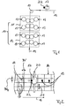
- Fig. 1 shows a schematic section of a trained as a newspaper printing press web printing machine in the region of an array 10 of two vertically superposed printing units 11, 12.
- Such an arrangement 10 is also referred to as a printing tower.
- the two printing units 11, 12 each have four printing units 13, wherein in the region of each printing unit 11, 12 a web-shaped substrate 14, which is transported in the vertical direction by the printing units 11, 12, on both sides, ie in the range of both printing material web surfaces, can be printed ,
- the printing units 11, 12 are used for static printing of the printing material web 14 with a printed image that is the same for all printed copies.
- Each printed copy contains several printed pages.
- the printing units 13 of the printing units 11, 12 are preferably designed as offset printing units. It is also possible that they are designed as gravure printing units.
- the printing material web 14 is deflectable on a deflection roller 15 in such a way that the printing material web 14 is transported in the direction of the arrow 16 following the deflection roller 15 substantially in the horizontal direction so as to convey the printing material web 14 supply static printed substrate web 14 of an inkjet printing device 17, which serves the dynamic printing of a printing substrate web surface of the printing material web 14 with a variable at least for some printed copies print image. This makes it possible to customize the printed in the printing units 11, 12, static print image.
- Fig. 2 shows the printing material web 14 to be printed in the area of the inkjet printing device 17 in plan view, with four printing pages 18 being printed side by side on the printing material web 14, as an example, viewed transversely to the transport direction (arrow 16) of the printing material web 14. According to Fig. 2 to be dynamized at a position 19 of one of these juxtaposed print pages 18 on the inkjet printing device 17, the previously printed static image of this print page 18.
- Fig. 2 is the position 19, at which on the inkjet printing device in the printing units 11, 12 printed static image printed dynamically and thus to be individualized, defined by the measures BV and BVq.
- the measure BV determines according to Fig. 2 the distance of the position 19 from a front seen in the transport direction of the arrow 16 edge of the inkjet printing device 17 to be printed on the pressure side 18.
- the dimension BVq determines the distance of the position 19 from a side edge of this print page 18th
- Fig. 2 Visible substrate web surface of the substrate web 14 automatically measured using a the inkjet printing device 17 associated sensor 22, wherein on the one hand depending on the measurement of the substrate automatically a transverse offset for the processing device is determined to the printing with the inkjet printing device 17 to be printed transversely to the transport direction Seen on the other hand, depending on the measurement of the printing substrate automatically a drive signal for the processing device is determined to the inkjet printing device 17 to be printed image in the transport direction of the Seen at the desired position on the substrate web or the corresponding printing side.
- the inkjet printing device 17 is positioned at the position 19 of the printing material web 14 transversely to the transport direction of the printing substrate web, so it is adapted to the dimension BVq for dynamic printing.
- the drive signal ensures that the dynamic print image to be printed with the inkjet printing device 17 is positioned at the desired position 19 on the printing material web 14 or the corresponding printed page 18 in the transport direction (arrow 16) of the printing substrate web, ie adapted to the measure BV becomes.
- the sensor 22 measures either the static print image or a print control mark printed outside the static print image.
- the sensor is preferably positioned in the immediate vicinity of the inkjet printing device 17 and forms a unit with the same.
- the automatically determined control signal is preferably offset by a travel delay, which depends on the transport speed of the printing substrate 14, the vertical distance of the inkjet printing device 17 from a printing substrate web surface to be printed web 14 and the running speed of the ink drops to be applied using the inkjet printing device 17 , These three sizes determine the runtime offset.
- the running speed of the ink droplets is the running speed of the processing medium of the processing device designed as an inkjet printing device 17. In other processing devices, such as e.g. For a laser cutter, this running speed is almost infinite, so the skew can be neglected.
- the automatically determined transverse offset is offset with an operating offset, which a printer manually specifies for the individual influencing of the desired position of the processing to be carried out with the processing device, viewed transversely to the transport direction of the printing material web.
- the automatically determined control signal is preferably offset with an operating offset which a printer manually specifies for the individual influencing of the desired position of the processing unit to be executed in the transport direction of the printing material web.
Landscapes
- Engineering & Computer Science (AREA)
- Mechanical Engineering (AREA)
- Handling Of Sheets (AREA)
- Ink Jet (AREA)
- Perforating, Stamping-Out Or Severing By Means Other Than Cutting (AREA)
- Auxiliary Devices For And Details Of Packaging Control (AREA)
- Treatment Of Fiber Materials (AREA)
Claims (5)
- Procédé de gestion d'une installation de travail intégrée à une machine d'impression à bobines, notamment d'une installation d'impression à jet d'encre, pour l'impression dynamique d'au moins une surface de bande de matière d'impression comportant au moins une image d'impression variable pour certains exemplaires imprimés, pour positionner le traitement à effectuer à l'aide de l'installation de traitement dans une position souhaitée d'une surface de bande de matière d'impression ou dans une position souhaitée sur au moins un côté d'impression des exemplaires imprimés,
caractérisé en ce que- à l'aide d'un capteur associé à l'installation de travail, on mesure automatiquement une bande de matière d'impression, imprimée de manière statique dans des groupes d'impression de la machine d'impression à bobines,- en fonction de la mesure de la bande de matière d'impression, d'une part on détermine de manière automatique le décalage transversal pour l'installation de traitement, pour que le travail à effectuer à l'aide de l'installation de traitement, notamment l'image d'impression dynamique à réaliser avec l'installation d'impression par jet d'encre, vue transversalement à la direction de transport de la bande de matière d'impression, se trouve dans la position souhaitée de la bande de matière d'impression ou sur le côté d'impression correspondant, et- en fonction de la mesure de la bande de matière d'impression d'autre part, on détermine automatiquement, un signal de commande pour l'installation de traitement, pour que le traitement à effectuer avec l'installation de traitement, notamment l'image d'impression dynamique à imprimer avec l'installation d'impression à jet d'encre, vue dans la direction de transport de la bande de matière d'impression, soit positionnée sur la bande de matière d'impression ou sur le côté d'impression correspondant à l'envoi souhaité. - Procédé selon la revendication 1,
caractérisé en ce qu'
un capteur positionné à proximité de l'installation de traitement, mesure soit l'image d'impression statique, soit un repère de contrôle d'impression, imprimé à l'extérieur de l'image d'impression statique. - Procédé selon la revendication 1 ou 2,
caractérisé en ce que
le décalage transversal déterminé de manière automatique, est calculé par un équipement de service, décalage qu'un imprimeur prédéfinit manuellement pour influencer individuellement la position souhaitée, transversalement à la direction de transport de la bande de matière d'impression pour le travail à exécuter par l'installation de traitement. - Procédé selon l'une des revendications 1 à 3,
caractérisé en ce que
le signal de commande défini de manière automatique, est calculé avec un décalage de service qu'un imprimeur prédéfinit manuellement pour influencer individuellement la position souhaitée, vue dans la direction de transport de la bande de matière d'impression pour le travail à exécuter dans l'installation de traitement. - Procédé selon l'une des revendications 1 à 4,
caractérisé en ce que
le signal de commande défini de manière automatique est définit en fonction du décalage de temps de parcours,
le décalage de temps de parcours dépendant de la vitesse de transport de la bande de matière d'impression, de la distance verticale de l'installation d'impression par rapport à la surface à traiter de la bande de matière d'impression, ainsi que de la vitesse de défilement de l'agent d'impression utilisé par l'installation d'impression.
Applications Claiming Priority (1)
| Application Number | Priority Date | Filing Date | Title |
|---|---|---|---|
| DE102007028452A DE102007028452A1 (de) | 2007-06-18 | 2007-06-18 | Verfahren zum Betreiben einer in eine Rollendruckmaschine integrierten Bearbeitungseinrichtung |
Publications (2)
| Publication Number | Publication Date |
|---|---|
| EP2006101A1 EP2006101A1 (fr) | 2008-12-24 |
| EP2006101B1 true EP2006101B1 (fr) | 2010-03-10 |
Family
ID=39684249
Family Applications (1)
| Application Number | Title | Priority Date | Filing Date |
|---|---|---|---|
| EP08010932A Not-in-force EP2006101B1 (fr) | 2007-06-18 | 2008-06-17 | Procédé de fonctionnement d'un dispositif de traitement intégré dans une presse rotative |
Country Status (4)
| Country | Link |
|---|---|
| EP (1) | EP2006101B1 (fr) |
| AT (1) | ATE460281T1 (fr) |
| DE (2) | DE102007028452A1 (fr) |
| WO (1) | WO2008155100A1 (fr) |
Families Citing this family (4)
| Publication number | Priority date | Publication date | Assignee | Title |
|---|---|---|---|---|
| DE102012107664B4 (de) | 2012-08-21 | 2014-03-06 | Manroland Web Systems Gmbh | Digitaldruckeinrichtung zum dynamischen Bedrucken einer statisch bedruckten Bedruckstoffbahn und Rollendruckmaschine |
| CN103240975A (zh) * | 2013-05-06 | 2013-08-14 | 中粮包装(天津)有限公司 | 一种六色uv印刷线 |
| DE102013211250B4 (de) | 2013-06-17 | 2019-05-02 | Koenig & Bauer Ag | Druckmaschine mit mehreren gemeinsam einen Bedruckstoff bedruckenden Druckwerken |
| JP2023540939A (ja) | 2020-09-03 | 2023-09-27 | テトラ ラバル ホールディングス アンド ファイナンス エス エイ | 印刷方法及びシステム |
Family Cites Families (10)
| Publication number | Priority date | Publication date | Assignee | Title |
|---|---|---|---|---|
| JPS6096461A (ja) * | 1983-11-01 | 1985-05-30 | Toppan Printing Co Ltd | 検査マ−クの設けられた巻取状印刷紙 |
| US4700627A (en) * | 1986-01-28 | 1987-10-20 | Case-Hoyt | Method and apparatus for marking defective portions of a printed web |
| DE4432371B4 (de) * | 1994-09-12 | 2004-12-09 | Heidelberger Druckmaschinen Ag | Verfahren zum Drucken und Weiterverarbeiten von Nutzen |
| JP2946201B2 (ja) * | 1997-04-17 | 1999-09-06 | 株式会社東京機械製作所 | 付加印刷装置付き輪転機及び付加印刷装置付き印刷ユニット |
| DE19802920B4 (de) * | 1998-01-27 | 2008-01-31 | Man Roland Druckmaschinen Ag | Verfahren und Vorrichtung zur Farbregelung in Druckmaschinen |
| FR2775930B1 (fr) * | 1998-03-11 | 2000-06-02 | Heidelberger Druckmasch Ag | Dispositif de commande de l'impression de bande de matiere dans une machine rotative a imprimer |
| JP2002357555A (ja) * | 2001-06-04 | 2002-12-13 | Dainippon Printing Co Ltd | 印刷物検査装置 |
| DE20303574U1 (de) * | 2003-03-06 | 2003-04-30 | MAN Roland Druckmaschinen AG, 63075 Offenbach | Bildinspektionssystem für eine Druckmaschine |
| DE10332211B3 (de) * | 2003-07-16 | 2005-02-10 | Koenig & Bauer Ag | Maschine zur Verarbeitung von Bogen |
| PL1699637T3 (pl) * | 2003-08-01 | 2015-07-31 | Manroland Web Systems Gmbh | Sposób i przyrząd do dodatkowego zadruku z wykorzystaniem przewodnictwa elektrycznego |
-
2007
- 2007-06-18 DE DE102007028452A patent/DE102007028452A1/de not_active Withdrawn
-
2008
- 2008-06-17 DE DE502008000425T patent/DE502008000425D1/de active Active
- 2008-06-17 AT AT08010932T patent/ATE460281T1/de active
- 2008-06-17 EP EP08010932A patent/EP2006101B1/fr not_active Not-in-force
- 2008-06-18 WO PCT/EP2008/004890 patent/WO2008155100A1/fr not_active Ceased
Also Published As
| Publication number | Publication date |
|---|---|
| WO2008155100A1 (fr) | 2008-12-24 |
| DE502008000425D1 (de) | 2010-04-22 |
| ATE460281T1 (de) | 2010-03-15 |
| DE102007028452A1 (de) | 2008-12-24 |
| EP2006101A1 (fr) | 2008-12-24 |
Similar Documents
| Publication | Publication Date | Title |
|---|---|---|
| EP1839860B1 (fr) | Dispositif de transfert de feuille avec dispositif de traitement ultérieur intégré | |
| EP2045076B1 (fr) | Presse rotative à bandes | |
| DE60220195T2 (de) | Druckzeilen- und Farbausrichtungskontrolle für Vielfachlaufdruck | |
| EP1810826A2 (fr) | Machine d'impression de feuilles | |
| EP2943340B1 (fr) | Procédé permettant de fabriquer une bande de papier sans fin | |
| EP3201000B1 (fr) | Dispositif de codage de feuilles à imprimer dans une presse à feuilles | |
| DE102009000513B4 (de) | Bogendruckmaschine | |
| EP2006101A1 (fr) | Procédé de fonctionnement d'un dispositif de traitement intégré dans une presse rotative | |
| DE102013211250B4 (de) | Druckmaschine mit mehreren gemeinsam einen Bedruckstoff bedruckenden Druckwerken | |
| DE102005060441A1 (de) | Bogendruckmaschine | |
| EP2862715B1 (fr) | Presse | |
| WO2010086263A1 (fr) | Presse à feuilles | |
| EP2006100B1 (fr) | Procédé de contrôle d'une presse rotative | |
| EP2006107B1 (fr) | Procédé de détermination d'un signal de commande pour un dispositif de traitement intégré dans une presse rotative | |
| EP2113384B1 (fr) | Procédé de fonctionnement d'un dispositif de traitement intégré dans une presse rotative | |
| DE69915957T2 (de) | Selektiver flexodruck mit einer beweglichen aniloxwalze | |
| DE102019114981B3 (de) | Vorrichtungen und Verfahren zum Transport in einer Bogenbearbeitungsmaschine mit einem Transportband | |
| EP3003721B1 (fr) | Procédé de réimpression d'au moins un exemplaire imprimé individualisé | |
| DE102007046773B4 (de) | Verfahren zum Betreiben einer in eine Rollendruckmaschine integrierten Bearbeitungseinrichtung | |
| DE102023134235B3 (de) | Verfahren zum Ausrichten von Non Impact Druckköpfen | |
| EP3984749A1 (fr) | Procédé de réalisation de produits imprimés | |
| DE102007044622A1 (de) | Rollendruckmaschine | |
| DE102013211251B4 (de) | Druckmaschine mit mehreren gemeinsam einen Bedruckstoff bedruckenden Druckwerken | |
| DE19856857A1 (de) | Verfahren zum Beschichten eines Bedruckstoffes in einer Druckmaschine | |
| DE102013211255B4 (de) | Druckmaschine mit mehreren gemeinsam einen Bedruckstoff bedruckenden Druckwerken |
Legal Events
| Date | Code | Title | Description |
|---|---|---|---|
| PUAI | Public reference made under article 153(3) epc to a published international application that has entered the european phase |
Free format text: ORIGINAL CODE: 0009012 |
|
| AK | Designated contracting states |
Kind code of ref document: A1 Designated state(s): AT BE BG CH CY CZ DE DK EE ES FI FR GB GR HR HU IE IS IT LI LT LU LV MC MT NL NO PL PT RO SE SI SK TR |
|
| AX | Request for extension of the european patent |
Extension state: AL BA MK RS |
|
| 17P | Request for examination filed |
Effective date: 20090620 |
|
| AKX | Designation fees paid |
Designated state(s): AT BE BG CH CY CZ DE DK EE ES FI FR GB GR HR HU IE IS IT LI LT LU LV MC MT NL NO PL PT RO SE SI SK TR |
|
| GRAP | Despatch of communication of intention to grant a patent |
Free format text: ORIGINAL CODE: EPIDOSNIGR1 |
|
| GRAS | Grant fee paid |
Free format text: ORIGINAL CODE: EPIDOSNIGR3 |
|
| GRAA | (expected) grant |
Free format text: ORIGINAL CODE: 0009210 |
|
| AK | Designated contracting states |
Kind code of ref document: B1 Designated state(s): AT BE BG CH CY CZ DE DK EE ES FI FR GB GR HR HU IE IS IT LI LT LU LV MC MT NL NO PL PT RO SE SI SK TR |
|
| REG | Reference to a national code |
Ref country code: GB Ref legal event code: FG4D Free format text: NOT ENGLISH |
|
| REG | Reference to a national code |
Ref country code: CH Ref legal event code: EP Ref country code: CH Ref legal event code: NV Representative=s name: E. BLUM & CO. AG PATENT- UND MARKENANWAELTE VSP |
|
| REG | Reference to a national code |
Ref country code: IE Ref legal event code: FG4D |
|
| REF | Corresponds to: |
Ref document number: 502008000425 Country of ref document: DE Date of ref document: 20100422 Kind code of ref document: P |
|
| REG | Reference to a national code |
Ref country code: NL Ref legal event code: VDEP Effective date: 20100310 |
|
| PG25 | Lapsed in a contracting state [announced via postgrant information from national office to epo] |
Ref country code: NO Free format text: LAPSE BECAUSE OF FAILURE TO SUBMIT A TRANSLATION OF THE DESCRIPTION OR TO PAY THE FEE WITHIN THE PRESCRIBED TIME-LIMIT Effective date: 20100610 Ref country code: HR Free format text: LAPSE BECAUSE OF FAILURE TO SUBMIT A TRANSLATION OF THE DESCRIPTION OR TO PAY THE FEE WITHIN THE PRESCRIBED TIME-LIMIT Effective date: 20100310 Ref country code: LT Free format text: LAPSE BECAUSE OF FAILURE TO SUBMIT A TRANSLATION OF THE DESCRIPTION OR TO PAY THE FEE WITHIN THE PRESCRIBED TIME-LIMIT Effective date: 20100310 |
|
| LTIE | Lt: invalidation of european patent or patent extension |
Effective date: 20100310 |
|
| PG25 | Lapsed in a contracting state [announced via postgrant information from national office to epo] |
Ref country code: LV Free format text: LAPSE BECAUSE OF FAILURE TO SUBMIT A TRANSLATION OF THE DESCRIPTION OR TO PAY THE FEE WITHIN THE PRESCRIBED TIME-LIMIT Effective date: 20100310 Ref country code: SI Free format text: LAPSE BECAUSE OF FAILURE TO SUBMIT A TRANSLATION OF THE DESCRIPTION OR TO PAY THE FEE WITHIN THE PRESCRIBED TIME-LIMIT Effective date: 20100310 Ref country code: PL Free format text: LAPSE BECAUSE OF FAILURE TO SUBMIT A TRANSLATION OF THE DESCRIPTION OR TO PAY THE FEE WITHIN THE PRESCRIBED TIME-LIMIT Effective date: 20100310 Ref country code: FI Free format text: LAPSE BECAUSE OF FAILURE TO SUBMIT A TRANSLATION OF THE DESCRIPTION OR TO PAY THE FEE WITHIN THE PRESCRIBED TIME-LIMIT Effective date: 20100310 |
|
| REG | Reference to a national code |
Ref country code: IE Ref legal event code: FD4D |
|
| PG25 | Lapsed in a contracting state [announced via postgrant information from national office to epo] |
Ref country code: CY Free format text: LAPSE BECAUSE OF FAILURE TO SUBMIT A TRANSLATION OF THE DESCRIPTION OR TO PAY THE FEE WITHIN THE PRESCRIBED TIME-LIMIT Effective date: 20100310 Ref country code: EE Free format text: LAPSE BECAUSE OF FAILURE TO SUBMIT A TRANSLATION OF THE DESCRIPTION OR TO PAY THE FEE WITHIN THE PRESCRIBED TIME-LIMIT Effective date: 20100310 Ref country code: ES Free format text: LAPSE BECAUSE OF FAILURE TO SUBMIT A TRANSLATION OF THE DESCRIPTION OR TO PAY THE FEE WITHIN THE PRESCRIBED TIME-LIMIT Effective date: 20100621 Ref country code: GR Free format text: LAPSE BECAUSE OF FAILURE TO SUBMIT A TRANSLATION OF THE DESCRIPTION OR TO PAY THE FEE WITHIN THE PRESCRIBED TIME-LIMIT Effective date: 20100611 Ref country code: NL Free format text: LAPSE BECAUSE OF FAILURE TO SUBMIT A TRANSLATION OF THE DESCRIPTION OR TO PAY THE FEE WITHIN THE PRESCRIBED TIME-LIMIT Effective date: 20100310 Ref country code: RO Free format text: LAPSE BECAUSE OF FAILURE TO SUBMIT A TRANSLATION OF THE DESCRIPTION OR TO PAY THE FEE WITHIN THE PRESCRIBED TIME-LIMIT Effective date: 20100310 Ref country code: SE Free format text: LAPSE BECAUSE OF FAILURE TO SUBMIT A TRANSLATION OF THE DESCRIPTION OR TO PAY THE FEE WITHIN THE PRESCRIBED TIME-LIMIT Effective date: 20100310 |
|
| PG25 | Lapsed in a contracting state [announced via postgrant information from national office to epo] |
Ref country code: BG Free format text: LAPSE BECAUSE OF FAILURE TO SUBMIT A TRANSLATION OF THE DESCRIPTION OR TO PAY THE FEE WITHIN THE PRESCRIBED TIME-LIMIT Effective date: 20100610 Ref country code: CZ Free format text: LAPSE BECAUSE OF FAILURE TO SUBMIT A TRANSLATION OF THE DESCRIPTION OR TO PAY THE FEE WITHIN THE PRESCRIBED TIME-LIMIT Effective date: 20100310 Ref country code: IS Free format text: LAPSE BECAUSE OF FAILURE TO SUBMIT A TRANSLATION OF THE DESCRIPTION OR TO PAY THE FEE WITHIN THE PRESCRIBED TIME-LIMIT Effective date: 20100710 Ref country code: SK Free format text: LAPSE BECAUSE OF FAILURE TO SUBMIT A TRANSLATION OF THE DESCRIPTION OR TO PAY THE FEE WITHIN THE PRESCRIBED TIME-LIMIT Effective date: 20100310 |
|
| BERE | Be: lapsed |
Owner name: MANROLAND A.G. Effective date: 20100630 |
|
| PLBE | No opposition filed within time limit |
Free format text: ORIGINAL CODE: 0009261 |
|
| STAA | Information on the status of an ep patent application or granted ep patent |
Free format text: STATUS: NO OPPOSITION FILED WITHIN TIME LIMIT |
|
| PG25 | Lapsed in a contracting state [announced via postgrant information from national office to epo] |
Ref country code: DK Free format text: LAPSE BECAUSE OF FAILURE TO SUBMIT A TRANSLATION OF THE DESCRIPTION OR TO PAY THE FEE WITHIN THE PRESCRIBED TIME-LIMIT Effective date: 20100310 Ref country code: IE Free format text: LAPSE BECAUSE OF FAILURE TO SUBMIT A TRANSLATION OF THE DESCRIPTION OR TO PAY THE FEE WITHIN THE PRESCRIBED TIME-LIMIT Effective date: 20100310 Ref country code: MC Free format text: LAPSE BECAUSE OF NON-PAYMENT OF DUE FEES Effective date: 20100630 |
|
| 26N | No opposition filed |
Effective date: 20101213 |
|
| PG25 | Lapsed in a contracting state [announced via postgrant information from national office to epo] |
Ref country code: IT Free format text: LAPSE BECAUSE OF FAILURE TO SUBMIT A TRANSLATION OF THE DESCRIPTION OR TO PAY THE FEE WITHIN THE PRESCRIBED TIME-LIMIT Effective date: 20100310 |
|
| PG25 | Lapsed in a contracting state [announced via postgrant information from national office to epo] |
Ref country code: MT Free format text: LAPSE BECAUSE OF FAILURE TO SUBMIT A TRANSLATION OF THE DESCRIPTION OR TO PAY THE FEE WITHIN THE PRESCRIBED TIME-LIMIT Effective date: 20100310 |
|
| PG25 | Lapsed in a contracting state [announced via postgrant information from national office to epo] |
Ref country code: BE Free format text: LAPSE BECAUSE OF NON-PAYMENT OF DUE FEES Effective date: 20100630 |
|
| PGFP | Annual fee paid to national office [announced via postgrant information from national office to epo] |
Ref country code: FR Payment date: 20110630 Year of fee payment: 4 |
|
| REG | Reference to a national code |
Ref country code: DE Ref legal event code: R081 Ref document number: 502008000425 Country of ref document: DE Owner name: MANROLAND WEB SYSTEMS GMBH, DE Free format text: FORMER OWNER: MANROLAND AG, 63075 OFFENBACH, DE Effective date: 20120626 |
|
| PG25 | Lapsed in a contracting state [announced via postgrant information from national office to epo] |
Ref country code: HU Free format text: LAPSE BECAUSE OF FAILURE TO SUBMIT A TRANSLATION OF THE DESCRIPTION OR TO PAY THE FEE WITHIN THE PRESCRIBED TIME-LIMIT Effective date: 20100911 Ref country code: LU Free format text: LAPSE BECAUSE OF NON-PAYMENT OF DUE FEES Effective date: 20100617 Ref country code: PT Free format text: LAPSE BECAUSE OF FAILURE TO SUBMIT A TRANSLATION OF THE DESCRIPTION OR TO PAY THE FEE WITHIN THE PRESCRIBED TIME-LIMIT Effective date: 20100810 |
|
| PG25 | Lapsed in a contracting state [announced via postgrant information from national office to epo] |
Ref country code: TR Free format text: LAPSE BECAUSE OF FAILURE TO SUBMIT A TRANSLATION OF THE DESCRIPTION OR TO PAY THE FEE WITHIN THE PRESCRIBED TIME-LIMIT Effective date: 20100310 |
|
| GBPC | Gb: european patent ceased through non-payment of renewal fee |
Effective date: 20120617 |
|
| REG | Reference to a national code |
Ref country code: FR Ref legal event code: ST Effective date: 20130228 |
|
| PG25 | Lapsed in a contracting state [announced via postgrant information from national office to epo] |
Ref country code: GB Free format text: LAPSE BECAUSE OF NON-PAYMENT OF DUE FEES Effective date: 20120617 Ref country code: FR Free format text: LAPSE BECAUSE OF NON-PAYMENT OF DUE FEES Effective date: 20120702 |
|
| REG | Reference to a national code |
Ref country code: AT Ref legal event code: MM01 Ref document number: 460281 Country of ref document: AT Kind code of ref document: T Effective date: 20130617 |
|
| PG25 | Lapsed in a contracting state [announced via postgrant information from national office to epo] |
Ref country code: AT Free format text: LAPSE BECAUSE OF NON-PAYMENT OF DUE FEES Effective date: 20130617 |
|
| REG | Reference to a national code |
Ref country code: CH Ref legal event code: PUE Owner name: MANROLAND WEB SYSTEMS GMBH, DE Free format text: FORMER OWNER: MANROLAND AG, DE |
|
| PGFP | Annual fee paid to national office [announced via postgrant information from national office to epo] |
Ref country code: CH Payment date: 20180621 Year of fee payment: 11 |
|
| REG | Reference to a national code |
Ref country code: DE Ref legal event code: R081 Ref document number: 502008000425 Country of ref document: DE Owner name: MANROLAND GOSS WEB SYSTEMS GMBH, DE Free format text: FORMER OWNER: MANROLAND WEB SYSTEMS GMBH, 86153 AUGSBURG, DE |
|
| REG | Reference to a national code |
Ref country code: CH Ref legal event code: PL |
|
| PG25 | Lapsed in a contracting state [announced via postgrant information from national office to epo] |
Ref country code: LI Free format text: LAPSE BECAUSE OF NON-PAYMENT OF DUE FEES Effective date: 20190630 Ref country code: CH Free format text: LAPSE BECAUSE OF NON-PAYMENT OF DUE FEES Effective date: 20190630 |
|
| PGFP | Annual fee paid to national office [announced via postgrant information from national office to epo] |
Ref country code: DE Payment date: 20240719 Year of fee payment: 17 |
|
| REG | Reference to a national code |
Ref country code: DE Ref legal event code: R119 Ref document number: 502008000425 Country of ref document: DE |
|
| PG25 | Lapsed in a contracting state [announced via postgrant information from national office to epo] |
Ref country code: DE Free format text: LAPSE BECAUSE OF NON-PAYMENT OF DUE FEES Effective date: 20260101 |