EP2006156A2 - Dispositif de fixation pour le rétroviseur intérieur de véhicules automobiles sur la face intérieure d'un pare-brise - Google Patents
Dispositif de fixation pour le rétroviseur intérieur de véhicules automobiles sur la face intérieure d'un pare-brise Download PDFInfo
- Publication number
- EP2006156A2 EP2006156A2 EP08003423A EP08003423A EP2006156A2 EP 2006156 A2 EP2006156 A2 EP 2006156A2 EP 08003423 A EP08003423 A EP 08003423A EP 08003423 A EP08003423 A EP 08003423A EP 2006156 A2 EP2006156 A2 EP 2006156A2
- Authority
- EP
- European Patent Office
- Prior art keywords
- receiving part
- fastening device
- mirror
- mirror base
- grooves
- Prior art date
- Legal status (The legal status is an assumption and is not a legal conclusion. Google has not performed a legal analysis and makes no representation as to the accuracy of the status listed.)
- Granted
Links
Images

Classifications
-
- B—PERFORMING OPERATIONS; TRANSPORTING
- B60—VEHICLES IN GENERAL
- B60R—VEHICLES, VEHICLE FITTINGS, OR VEHICLE PARTS, NOT OTHERWISE PROVIDED FOR
- B60R1/00—Optical viewing arrangements; Real-time viewing arrangements for drivers or passengers using optical image capturing systems, e.g. cameras or video systems specially adapted for use in or on vehicles
- B60R1/02—Rear-view mirror arrangements
- B60R1/04—Rear-view mirror arrangements mounted inside vehicle
Definitions
- the invention relates to a fastening device for an interior rearview mirror of motor vehicles on the inside of a windshield, wherein on the windshield a held by gluing in position receiving part is provided on which a mirror of the interior rearview mirror is detachably attached.
- the side edges of the V-shaped grooves are kept relatively thin, so that they can spring up elastically during assembly of the mirror base.
- this fastening device in the connecting portion receiving part / mirror base on a relatively low rigidity, whereby disturbing mirror glass vibrations can occur in the dynamic driving operation of the vehicle.
- this fastening device is statically overdetermined.
- the object of the invention is to further develop a fastening device for an interior rearview mirror of motor vehicles on the inside of a windshield so that the connection between the receiving part and the mirror base static exactly is defined and has a high rigidity, so that the mirror glass vibration behavior is significantly improved while driving.
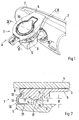
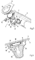
- a fastening device 1 for an interior rearview mirror 2 of motor vehicles wherein the interior rearview mirror 2 is fixed to the inside 3 of a windshield 4 with the interposition of a receiving part 5.
- the interior rearview mirror 2 is composed of a mirror base 6 and an articulated mirror head 7 connected thereto.
- the low-height having receiving part 5 is fixed by gluing to the inside 3 of the windshield 4 and is made in the embodiment of a fiber-reinforced plastic. However, it could also be made of a sintered metal.
- the receiving part 5 serves to support and support the interior rearview mirror 2.
- the partially annular receiving part 5 has a central recess 9.
- a sensor element 10 is used, which is pressed with mounted rearview mirror 2 by a non-illustrated pressure spring with bias against the inside 3 of the windshield 4.
- the sensor element 10 may include one or more sensors.
- the sensor element 10 has a rain sensor, a light sensor and a humidity sensor.
- the shape of the recess 9 is adapted to the outer contour of the sensor element 10, so that it is positioned in the recess 9 of the receiving part 5 in the correct position and secure against displacement.
- the mirror base 6 is supported in its mounted operating position A only on a six-point support 11 directly on the receiving part 5 and secured by a separate holding device 12 on the receiving part 5.
- a six-point support 11 is each provided on the receiving part 5 and the mirror 6 three offset from each other, formed above supporting elements 13, 14 are provided.
- On the support elements 13, 14 of the mirror base 6 or the receiving part 5 are each protruding prism guides 15 are formed, which cooperate positively with corresponding profiled, recessed receiving grooves 16 of the other part.
- the prism guides 15 have the shape of a triangular prism 17.
- the side surfaces 18, 19 of the prism guides 15 extend at an angle ⁇ to each other, wherein the angle ⁇ is preferably between 60 and 120 °.
- the two side surfaces 18, 19 are approximately the same length.
- the protruding prism guides 15 are provided on the support elements 14 of the mirror base 6, whereas the recessed receiving grooves 16 are formed on the support elements 13 of the receiving part 5.
- the correspondingly formed recessed side surfaces 21, 22 of the grooves 16 also form two obliquely extending bearing surfaces of a support element 13, 14 of the six-point support 11.
- the two side surfaces 18, 19 of the prism guides 15 are connected to each other via a radii-shaped transition region 23, wherein the Radius of this transition region 23 is greater than the relatively small radius between the two side surfaces 21, 22 of the grooves 16.
- the mirror 6 is located at each of its three support elements 14 with the inclined side surface 18 partially on the rectified side surface 21 of the support member 13, whereas the angularly extending to the side surface 18 side surface 19 of the support element 14 on the rectified Side surface 22 of the receiving part 5 arranged support member 13 is supported. Between the three pairs of support elements 13, 14, the receiving part 5 extends at an axial distance (dimension B) to the mirror 6.
- the three supporting elements 13, 14, which are each formed integrally with the receiving part 5 or the mirror base 6, are arranged in a star shape relative to a theoretical center and are each offset by 90 ° to 135 °, preferably by approximately 120 °.
- the support elements 13 of the receiving part 5 are integrally formed on the windshield 4 side facing away from a partially annular collar 24 of the receiving part 5.
- the support parts 14 of the mirror base 6, preferably made of an aluminum alloy or of plastic, are integrally formed on the front side 25 of the mirror base 6 facing the receiving part 5.
- each insertion bevel 26 of the prism guide 15 and the insertion bevel 27 of the receiving groove 16 is assigned.
- the mutually facing end faces 28, 29 of each two corresponding support elements 13, 14 extend at a small axial distance (dimension C), so that the receiving part 5 and the mirror 6 rest only locally on six inclined contact surfaces or support each other.
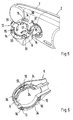
- the holding device 12 for the mirror base 6 comprises a connected to the mirror 6 support member 30 which has at least two parked in the direction of receiving part 5 resilient retaining tongues 31 which engage behind with mounted mirror 6 in radially arranged locking grooves 32 of the receiving part 5.
- the holding element 30 rests with an annular bottom portion 33 on the substantially flat end face 25 of the mirror base 6 and is firmly connected thereto.
- the bottom portion 33 is connected to the mirror base 6 via two spaced-apart screw fasteners, not shown.
- Fig. 5 has the holding element 3 star-shaped resilient holding tongues 31 arranged on each other.
- the Latching grooves 32 are provided locally on the outside of the annular collar 24 of the receiving part 5.
- the detent grooves 32 are each preceded by spare regions 34 on the receiving part 5 so that the retaining tongues 31 of the mirror base 6 can be brought into a pre-locked position.
- a subsequent rotation of the mirror base 6 relative to the receiving part 5 by an angle of about 10 to 20 ° clockwise setting of the mirror base 6 takes place on the receiving part 5.
- the determination of the mirror base 6 takes place in principle as the bayonet lock for a lens.
- the largest part of the mirror base 6, the receiving part 5 and the holding element 30 is covered by a multi-part cover 35, which is fixed after mounting the interior rearview mirror 2 on the mirror 6 (eg by plugging or clipping).
Landscapes
- Engineering & Computer Science (AREA)
- Multimedia (AREA)
- Mechanical Engineering (AREA)
- Rear-View Mirror Devices That Are Mounted On The Exterior Of The Vehicle (AREA)
Applications Claiming Priority (1)
| Application Number | Priority Date | Filing Date | Title |
|---|---|---|---|
| DE102007028162A DE102007028162A1 (de) | 2007-06-20 | 2007-06-20 | Befestigungseinrichtung für einen Innenrückblickspiegel von Kraftfahrzeugen an einer Innenseite einer Windschutzscheibe |
Publications (3)
| Publication Number | Publication Date |
|---|---|
| EP2006156A2 true EP2006156A2 (fr) | 2008-12-24 |
| EP2006156A3 EP2006156A3 (fr) | 2010-01-27 |
| EP2006156B1 EP2006156B1 (fr) | 2011-11-30 |
Family
ID=39809371
Family Applications (1)
| Application Number | Title | Priority Date | Filing Date |
|---|---|---|---|
| EP08003423A Active EP2006156B1 (fr) | 2007-06-20 | 2008-02-26 | Dispositif de fixation pour le rétroviseur intérieur de véhicules automobiles sur la face intérieure d'un pare-brise |
Country Status (3)
| Country | Link |
|---|---|
| US (1) | US7726623B2 (fr) |
| EP (1) | EP2006156B1 (fr) |
| DE (1) | DE102007028162A1 (fr) |
Cited By (1)
| Publication number | Priority date | Publication date | Assignee | Title |
|---|---|---|---|---|
| WO2021104769A1 (fr) * | 2019-11-25 | 2021-06-03 | Bayerische Motoren Werke Aktiengesellschaft | Agencement de montage pour capteur |
Families Citing this family (28)
| Publication number | Priority date | Publication date | Assignee | Title |
|---|---|---|---|---|
| DE102008032400A1 (de) * | 2007-07-10 | 2009-06-25 | Continental Teves Ag & Co. Ohg | Vorrichtung zur Aufnahme von Fahrzeugsensoren |
| US8414137B2 (en) * | 2010-10-28 | 2013-04-09 | GM Global Technology Operations LLC | Inside rearview mirror assembly |
| DE102011101016B3 (de) * | 2011-05-10 | 2012-09-06 | Audi Ag | Halterung für einen Innenspiegel im Innenraum von Kraftfahrzeugen |
| US8925891B2 (en) * | 2011-09-14 | 2015-01-06 | Gentex Corporation | Reverse detach mounting system |
| DE102011122507A1 (de) * | 2011-12-28 | 2013-07-04 | Schneider Electric Industries Sas | Kommunikationseinheit |
| US9244249B2 (en) * | 2012-09-28 | 2016-01-26 | Gentex Corporation | Double ball slide on mount with screw over sensor |
| ITTO20121088A1 (it) * | 2012-12-17 | 2014-06-18 | Fiat Group Automobiles Spa | Braccio di collegamento per collegare uno specchietto retrovisore ad un elemento di sostegno fissato ad un parabrezza |
| US10434946B2 (en) | 2014-02-12 | 2019-10-08 | Gentex Corporation | Spring secured mounting system |
| KR101592737B1 (ko) * | 2014-07-17 | 2016-02-12 | 현대자동차주식회사 | 자동차의 통합형 인사이드 미러 조립체 |
| WO2018168265A1 (fr) * | 2017-03-13 | 2018-09-20 | 株式会社 村上開明堂 | Structure de fixation comprenant un mécanisme de retrait pour dispositif embarqué |
| DE102017007379B4 (de) * | 2017-08-05 | 2019-05-29 | Audi Ag | Haltevorrichtung |
| DE102017216637B4 (de) * | 2017-09-20 | 2021-04-22 | Bayerische Motoren Werke Aktiengesellschaft | Haltevorrichtung zum Halten einer Fahrzeugkomponente an einer Scheibenfläche eines Kraftfahrzeugs und eine derartige Vorrichtung umfassendes Kraftfahrzeug |
| DE102017216764A1 (de) | 2017-09-21 | 2019-03-21 | Volkswagen Aktiengesellschaft | Anordnung zur Befestigung eines Innenrückspiegels an einem Fahrzeug sowie Fahrzeug mit einer derartigen Befestigungsanordnung |
| US10190610B1 (en) | 2017-10-13 | 2019-01-29 | Gentex Corporation | Mounting assembly for rearview device |
| WO2019111234A1 (fr) | 2017-12-08 | 2019-06-13 | Gentex Corporation | Ensemble de montage de rétroviseur verrouillé par rotation à ressort à deux lobes préchargé |
| US10974650B2 (en) | 2017-12-11 | 2021-04-13 | Gentex Corporation | Rearview device mount and attachment method |
| WO2019151233A1 (fr) * | 2018-01-31 | 2019-08-08 | 株式会社 村上開明堂 | Structure de montage et embase de montage pour dispositif embarqué à monture pivotante monté sur pare-brise |
| JP1617360S (fr) * | 2018-01-31 | 2020-04-27 | ||
| CN111712405B (zh) * | 2018-01-31 | 2023-08-29 | 株式会社村上开明堂 | 旋转安装式的挡风玻璃安装型车辆用内后视镜的传感器组装构造 |
| JP1616719S (fr) * | 2018-01-31 | 2020-04-20 | ||
| JP1625045S (fr) * | 2018-07-27 | 2019-02-18 | ||
| JP1624950S (fr) * | 2018-07-27 | 2019-02-18 | ||
| EP3860880B1 (fr) | 2018-10-02 | 2022-12-21 | Gentex Corporation | Mécanisme de montage réglable pour un ensemble rétroviseur |
| CN109760586A (zh) * | 2018-12-29 | 2019-05-17 | 宁波汇铭视觉科技有限公司 | 一种汽车内后视镜装车安装结构 |
| DE102019118217A1 (de) * | 2019-07-05 | 2021-01-07 | HELLA GmbH & Co. KGaA | Gehäuse, insbesondere für eine Sensorvorrichtung |
| WO2021183593A1 (fr) * | 2020-03-10 | 2021-09-16 | Gentex Corporation | Rampes pour des supports d'ensemble rétroviseur |
| DE102022121391B3 (de) | 2022-08-24 | 2023-06-07 | Bayerische Motoren Werke Aktiengesellschaft | Grundplatte, spiegelfuss und montageanordnung zur anbringung eines innenspiegels für ein fahrzeug |
| DE102023202734A1 (de) * | 2023-03-27 | 2024-10-02 | Volkswagen Aktiengesellschaft | Anordnung und Fahrzeug |
Citations (2)
| Publication number | Priority date | Publication date | Assignee | Title |
|---|---|---|---|---|
| DE2015608A1 (de) | 1969-04-03 | 1970-10-15 | Ford-Werke AG, 5OOO Köln-Deutz | Befestigungseinrichtung für Innenspiegel von Kraftfahrzeugen |
| WO1993016900A1 (fr) | 1992-02-25 | 1993-09-02 | Gentex Corporation | Support amovible pour retroviseur |
Family Cites Families (9)
| Publication number | Priority date | Publication date | Assignee | Title |
|---|---|---|---|---|
| US3928894A (en) * | 1974-11-26 | 1975-12-30 | Illinois Tool Works | Adhesive mounting device |
| AU499884B2 (en) * | 1975-10-13 | 1979-05-03 | Lenheler Pty. Lid | Rear-vision mirror |
| US5058851A (en) | 1989-04-14 | 1991-10-22 | Donnelly Mirrors Limited | Mounting assembly for rearview mirror |
| US5377948A (en) | 1991-05-21 | 1995-01-03 | Gentex Corporation | Breakaway rearview mirror mounting bracket |
| US5820097A (en) * | 1997-01-10 | 1998-10-13 | Donnelly Corporation | Breakaway accessory mounting assembly for vehicles and windshield mounted button therefor |
| JP3686294B2 (ja) * | 1999-11-25 | 2005-08-24 | 株式会社東海理化電機製作所 | 車両用インナミラー装置 |
| JP3872790B2 (ja) * | 2001-11-16 | 2007-01-24 | 株式会社村上開明堂 | 車室内アクセサリ保持装置 |
| JP4481153B2 (ja) * | 2004-12-07 | 2010-06-16 | 株式会社東海理化電機製作所 | 車両用ドアミラー装置 |
| JP4713386B2 (ja) * | 2006-03-31 | 2011-06-29 | 株式会社村上開明堂 | 車室内アクセサリ保持装置 |
-
2007
- 2007-06-20 DE DE102007028162A patent/DE102007028162A1/de not_active Withdrawn
-
2008
- 2008-02-26 EP EP08003423A patent/EP2006156B1/fr active Active
- 2008-06-20 US US12/143,357 patent/US7726623B2/en active Active
Patent Citations (2)
| Publication number | Priority date | Publication date | Assignee | Title |
|---|---|---|---|---|
| DE2015608A1 (de) | 1969-04-03 | 1970-10-15 | Ford-Werke AG, 5OOO Köln-Deutz | Befestigungseinrichtung für Innenspiegel von Kraftfahrzeugen |
| WO1993016900A1 (fr) | 1992-02-25 | 1993-09-02 | Gentex Corporation | Support amovible pour retroviseur |
Cited By (4)
| Publication number | Priority date | Publication date | Assignee | Title |
|---|---|---|---|---|
| WO2021104769A1 (fr) * | 2019-11-25 | 2021-06-03 | Bayerische Motoren Werke Aktiengesellschaft | Agencement de montage pour capteur |
| CN114616136A (zh) * | 2019-11-25 | 2022-06-10 | 宝马股份公司 | 用于传感器的保持装置 |
| CN114616136B (zh) * | 2019-11-25 | 2024-01-02 | 宝马股份公司 | 用于传感器的保持装置 |
| US12172579B2 (en) | 2019-11-25 | 2024-12-24 | Bayerische Motoren Werke Aktiengesellschaft | Mounting arrangement for a sensor |
Also Published As
| Publication number | Publication date |
|---|---|
| US20080315060A1 (en) | 2008-12-25 |
| DE102007028162A1 (de) | 2008-12-24 |
| EP2006156A3 (fr) | 2010-01-27 |
| US7726623B2 (en) | 2010-06-01 |
| EP2006156B1 (fr) | 2011-11-30 |
Similar Documents
| Publication | Publication Date | Title |
|---|---|---|
| EP2006156B1 (fr) | Dispositif de fixation pour le rétroviseur intérieur de véhicules automobiles sur la face intérieure d'un pare-brise | |
| EP2315687B1 (fr) | Balai d'essuie-glace avec un element de raccord | |
| DE29906013U1 (de) | Innenrückblickspiegel für Fahrzeuge, insbesondere für Kraftfahrzeuge | |
| EP2098831B1 (fr) | Capteur doté d'un support | |
| DE112017005837B4 (de) | Montagestruktur für ein elektronisches fahrzeugbordgerät | |
| EP1641662B1 (fr) | Dispositif essuie-glace pour un vehicule automobile | |
| EP1170175A2 (fr) | Rétroviseur extérieur rabattable pour un véhicule | |
| EP1945486B1 (fr) | Balai d'essuie-glace | |
| DE3543815C2 (fr) | ||
| WO2007080007A1 (fr) | Essuie-glace | |
| EP0799744B1 (fr) | Rétroviseur réglable pour véhicules | |
| DE102008046981B4 (de) | Spiegelelement | |
| DE3413003A1 (de) | Fahrzeugscheibe | |
| EP0169348A1 (fr) | Monture d'une vitre, de préférence d'un pare-brise | |
| DE69910189T2 (de) | Vorrichtung zur befestigung eines messwertaufnehmers an einem wälzlager | |
| DE19652083A1 (de) | Zur Befestigung in einem Kraftfahrzeug vorgesehener Düsenstock | |
| EP0960760B1 (fr) | Dispositif de fixation pour une fenêtre de véhicule à moteur | |
| DE102006008306B3 (de) | Wagenheberaufnahme zur Befestigung an einer Karosserie eines Kraftwagens | |
| DE10000374A1 (de) | Wischblattanordnung sowie Verbindung zwischen einem Wischarm eines Scheibenwischers zum Reinigen von Scheiben an Fahrzeugen, insbesondere Kraftfahrzeugen, und einem Wischblatt | |
| DE60212312T2 (de) | Modul für den oberen Lenksäulenteil und Anordnung mit einem solchen Modul | |
| EP0728084B1 (fr) | Dispositif de guidage d'un arbre de commande et procede de montage d'un moteur avec son arbre de commande sur un vehicule | |
| EP1966010B1 (fr) | Equipement essuie-glace pour vehicule, notamment equipement essuie-glace arriere pour vehicule automobile | |
| DE8702684U1 (de) | Wischvorrichtung für Scheiben von Kraftfahrzeugen mit einem langgestreckten, einendig an einem Antriebselement befestigten Wischerarm | |
| EP1052166A2 (fr) | Arrangement de fixation d'un panneau en plastique transparent à un cadre, en particulier au flasque d'une carosserie | |
| DE102009013949A1 (de) | Befestigungsanordnung zur Befestigung eines Sensors an einer Fahrzeugscheibe |
Legal Events
| Date | Code | Title | Description |
|---|---|---|---|
| PUAI | Public reference made under article 153(3) epc to a published international application that has entered the european phase |
Free format text: ORIGINAL CODE: 0009012 |
|
| AK | Designated contracting states |
Kind code of ref document: A2 Designated state(s): AT BE BG CH CY CZ DE DK EE ES FI FR GB GR HR HU IE IS IT LI LT LU LV MC MT NL NO PL PT RO SE SI SK TR |
|
| AX | Request for extension of the european patent |
Extension state: AL BA MK RS |
|
| PUAL | Search report despatched |
Free format text: ORIGINAL CODE: 0009013 |
|
| AK | Designated contracting states |
Kind code of ref document: A3 Designated state(s): AT BE BG CH CY CZ DE DK EE ES FI FR GB GR HR HU IE IS IT LI LT LU LV MC MT NL NO PL PT RO SE SI SK TR |
|
| AX | Request for extension of the european patent |
Extension state: AL BA MK RS |
|
| RAP1 | Party data changed (applicant data changed or rights of an application transferred) |
Owner name: DR. ING. H.C. F. PORSCHE AG |
|
| 17P | Request for examination filed |
Effective date: 20100727 |
|
| 17Q | First examination report despatched |
Effective date: 20100817 |
|
| AKX | Designation fees paid |
Designated state(s): DE FR GB |
|
| GRAP | Despatch of communication of intention to grant a patent |
Free format text: ORIGINAL CODE: EPIDOSNIGR1 |
|
| GRAS | Grant fee paid |
Free format text: ORIGINAL CODE: EPIDOSNIGR3 |
|
| GRAA | (expected) grant |
Free format text: ORIGINAL CODE: 0009210 |
|
| AK | Designated contracting states |
Kind code of ref document: B1 Designated state(s): DE FR GB |
|
| REG | Reference to a national code |
Ref country code: GB Ref legal event code: FG4D Free format text: NOT ENGLISH |
|
| REG | Reference to a national code |
Ref country code: DE Ref legal event code: R096 Ref document number: 502008005705 Country of ref document: DE Effective date: 20120202 |
|
| PLBE | No opposition filed within time limit |
Free format text: ORIGINAL CODE: 0009261 |
|
| STAA | Information on the status of an ep patent application or granted ep patent |
Free format text: STATUS: NO OPPOSITION FILED WITHIN TIME LIMIT |
|
| 26N | No opposition filed |
Effective date: 20120831 |
|
| REG | Reference to a national code |
Ref country code: DE Ref legal event code: R097 Ref document number: 502008005705 Country of ref document: DE Effective date: 20120831 |
|
| REG | Reference to a national code |
Ref country code: FR Ref legal event code: PLFP Year of fee payment: 9 |
|
| REG | Reference to a national code |
Ref country code: FR Ref legal event code: PLFP Year of fee payment: 10 |
|
| REG | Reference to a national code |
Ref country code: FR Ref legal event code: PLFP Year of fee payment: 11 |
|
| PGFP | Annual fee paid to national office [announced via postgrant information from national office to epo] |
Ref country code: GB Payment date: 20190218 Year of fee payment: 12 |
|
| PGFP | Annual fee paid to national office [announced via postgrant information from national office to epo] |
Ref country code: FR Payment date: 20190220 Year of fee payment: 12 |
|
| GBPC | Gb: european patent ceased through non-payment of renewal fee |
Effective date: 20200226 |
|
| PG25 | Lapsed in a contracting state [announced via postgrant information from national office to epo] |
Ref country code: GB Free format text: LAPSE BECAUSE OF NON-PAYMENT OF DUE FEES Effective date: 20200226 Ref country code: FR Free format text: LAPSE BECAUSE OF NON-PAYMENT OF DUE FEES Effective date: 20200229 |
|
| P01 | Opt-out of the competence of the unified patent court (upc) registered |
Effective date: 20230526 |
|
| PGFP | Annual fee paid to national office [announced via postgrant information from national office to epo] |
Ref country code: DE Payment date: 20260218 Year of fee payment: 19 |