EP2006162A1 - Radarsensormontage für den toten Winkel von Fahrzeugen - Google Patents
Radarsensormontage für den toten Winkel von Fahrzeugen Download PDFInfo
- Publication number
- EP2006162A1 EP2006162A1 EP08009720A EP08009720A EP2006162A1 EP 2006162 A1 EP2006162 A1 EP 2006162A1 EP 08009720 A EP08009720 A EP 08009720A EP 08009720 A EP08009720 A EP 08009720A EP 2006162 A1 EP2006162 A1 EP 2006162A1
- Authority
- EP
- European Patent Office
- Prior art keywords
- sensor
- bracket
- vehicle
- fascia panel
- fascia
- Prior art date
- Legal status (The legal status is an assumption and is not a legal conclusion. Google has not performed a legal analysis and makes no representation as to the accuracy of the status listed.)
- Granted
Links
- 210000003195 fascia Anatomy 0.000 claims abstract description 72
- 239000000565 sealant Substances 0.000 claims abstract description 7
- XLYOFNOQVPJJNP-UHFFFAOYSA-N water Substances O XLYOFNOQVPJJNP-UHFFFAOYSA-N 0.000 claims abstract description 4
- 239000007787 solid Substances 0.000 claims description 12
- 239000011343 solid material Substances 0.000 abstract description 4
- 238000001514 detection method Methods 0.000 description 9
- 239000000463 material Substances 0.000 description 6
- 239000004033 plastic Substances 0.000 description 6
- 238000004519 manufacturing process Methods 0.000 description 4
- 230000009977 dual effect Effects 0.000 description 3
- 238000009434 installation Methods 0.000 description 3
- 229910052751 metal Inorganic materials 0.000 description 3
- 239000002184 metal Substances 0.000 description 3
- 239000000428 dust Substances 0.000 description 2
- 239000011152 fibreglass Substances 0.000 description 2
- FYYHWMGAXLPEAU-UHFFFAOYSA-N Magnesium Chemical compound [Mg] FYYHWMGAXLPEAU-UHFFFAOYSA-N 0.000 description 1
- 229910000831 Steel Inorganic materials 0.000 description 1
- 239000000853 adhesive Substances 0.000 description 1
- 230000001070 adhesive effect Effects 0.000 description 1
- 229910052782 aluminium Inorganic materials 0.000 description 1
- XAGFODPZIPBFFR-UHFFFAOYSA-N aluminium Chemical compound [Al] XAGFODPZIPBFFR-UHFFFAOYSA-N 0.000 description 1
- 238000005260 corrosion Methods 0.000 description 1
- 230000007797 corrosion Effects 0.000 description 1
- -1 dirt Substances 0.000 description 1
- 238000005516 engineering process Methods 0.000 description 1
- 239000006260 foam Substances 0.000 description 1
- 238000010438 heat treatment Methods 0.000 description 1
- JEIPFZHSYJVQDO-UHFFFAOYSA-N iron(III) oxide Inorganic materials O=[Fe]O[Fe]=O JEIPFZHSYJVQDO-UHFFFAOYSA-N 0.000 description 1
- 239000011499 joint compound Substances 0.000 description 1
- 229910052749 magnesium Inorganic materials 0.000 description 1
- 239000011777 magnesium Substances 0.000 description 1
- 238000000034 method Methods 0.000 description 1
- 239000002991 molded plastic Substances 0.000 description 1
- 238000000465 moulding Methods 0.000 description 1
- 230000000284 resting effect Effects 0.000 description 1
- 230000000717 retained effect Effects 0.000 description 1
- 239000005060 rubber Substances 0.000 description 1
- 239000010959 steel Substances 0.000 description 1
Images


Classifications
-
- B—PERFORMING OPERATIONS; TRANSPORTING
- B60—VEHICLES IN GENERAL
- B60R—VEHICLES, VEHICLE FITTINGS, OR VEHICLE PARTS, NOT OTHERWISE PROVIDED FOR
- B60R19/00—Wheel guards; Radiator guards, e.g. grilles; Obstruction removers; Fittings damping bouncing force in collisions
- B60R19/02—Bumpers, i.e. impact receiving or absorbing members for protecting vehicles or fending off blows from other vehicles or objects
- B60R19/48—Bumpers, i.e. impact receiving or absorbing members for protecting vehicles or fending off blows from other vehicles or objects combined with, or convertible into, other devices or objects, e.g. bumpers combined with road brushes, bumpers convertible into beds
- B60R19/483—Bumpers, i.e. impact receiving or absorbing members for protecting vehicles or fending off blows from other vehicles or objects combined with, or convertible into, other devices or objects, e.g. bumpers combined with road brushes, bumpers convertible into beds with obstacle sensors of electric or electronic type
-
- G—PHYSICS
- G01—MEASURING; TESTING
- G01S—RADIO DIRECTION-FINDING; RADIO NAVIGATION; DETERMINING DISTANCE OR VELOCITY BY USE OF RADIO WAVES; LOCATING OR PRESENCE-DETECTING BY USE OF THE REFLECTION OR RERADIATION OF RADIO WAVES; ANALOGOUS ARRANGEMENTS USING OTHER WAVES
- G01S13/00—Systems using the reflection or reradiation of radio waves, e.g. radar systems; Analogous systems using reflection or reradiation of waves whose nature or wavelength is irrelevant or unspecified
- G01S13/88—Radar or analogous systems specially adapted for specific applications
- G01S13/93—Radar or analogous systems specially adapted for specific applications for anti-collision purposes
- G01S13/931—Radar or analogous systems specially adapted for specific applications for anti-collision purposes of land vehicles
- G01S2013/9327—Sensor installation details
- G01S2013/93272—Sensor installation details in the back of the vehicles
-
- G—PHYSICS
- G01—MEASURING; TESTING
- G01S—RADIO DIRECTION-FINDING; RADIO NAVIGATION; DETERMINING DISTANCE OR VELOCITY BY USE OF RADIO WAVES; LOCATING OR PRESENCE-DETECTING BY USE OF THE REFLECTION OR RERADIATION OF RADIO WAVES; ANALOGOUS ARRANGEMENTS USING OTHER WAVES
- G01S13/00—Systems using the reflection or reradiation of radio waves, e.g. radar systems; Analogous systems using reflection or reradiation of waves whose nature or wavelength is irrelevant or unspecified
- G01S13/88—Radar or analogous systems specially adapted for specific applications
- G01S13/93—Radar or analogous systems specially adapted for specific applications for anti-collision purposes
- G01S13/931—Radar or analogous systems specially adapted for specific applications for anti-collision purposes of land vehicles
- G01S2013/9327—Sensor installation details
- G01S2013/93274—Sensor installation details on the side of the vehicles
-
- G—PHYSICS
- G01—MEASURING; TESTING
- G01S—RADIO DIRECTION-FINDING; RADIO NAVIGATION; DETERMINING DISTANCE OR VELOCITY BY USE OF RADIO WAVES; LOCATING OR PRESENCE-DETECTING BY USE OF THE REFLECTION OR RERADIATION OF RADIO WAVES; ANALOGOUS ARRANGEMENTS USING OTHER WAVES
- G01S13/00—Systems using the reflection or reradiation of radio waves, e.g. radar systems; Analogous systems using reflection or reradiation of waves whose nature or wavelength is irrelevant or unspecified
- G01S13/88—Radar or analogous systems specially adapted for specific applications
- G01S13/93—Radar or analogous systems specially adapted for specific applications for anti-collision purposes
- G01S13/931—Radar or analogous systems specially adapted for specific applications for anti-collision purposes of land vehicles
- G01S2013/9327—Sensor installation details
- G01S2013/93275—Sensor installation details in the bumper area
-
- G—PHYSICS
- G01—MEASURING; TESTING
- G01S—RADIO DIRECTION-FINDING; RADIO NAVIGATION; DETERMINING DISTANCE OR VELOCITY BY USE OF RADIO WAVES; LOCATING OR PRESENCE-DETECTING BY USE OF THE REFLECTION OR RERADIATION OF RADIO WAVES; ANALOGOUS ARRANGEMENTS USING OTHER WAVES
- G01S7/00—Details of systems according to groups G01S13/00, G01S15/00, G01S17/00
- G01S7/02—Details of systems according to groups G01S13/00, G01S15/00, G01S17/00 of systems according to group G01S13/00
- G01S7/027—Constructional details of housings, e.g. form, type, material or ruggedness
Definitions
- the present invention relates to a dual purpose bracket for mounting a radar sensor and a body panel fascia.
- Modern vehicles are commonly being equipped with radar systems such that while an equipped vehicle is traveling along a road detection of surrounding vehicles is possible, particularly vehicles in a blind spot of a driver. Such vehicle detection may assist a driver of the radar-equipped vehicle with a lane change, for example.
- a radar sensor as part of the radar system, may be mounted within a dedicated metal bracket under cover of a vehicle body panel.
- vehicle body panels also known as fascia, may be attached to an underlying vehicle structure using dedicated brackets specifically intended for such a mounting purpose. With single purpose or dedicated brackets, manufacturing costs, vehicle assembly costs, and the weight associated with such brackets contributes to excess manufacturing costs and vehicle weight.
- a structure for retaining a sensor, such as a radar sensor, and a body fascia panel may include a bracket, framework, or solid material that defines a receptacle or pocket to retain and secure the sensor.
- the bracket may secure a body fascia panel in a bracket slot such that an edge of the body fascia panel may reside, wedge or clip into the bracket or solid material structure.
- the structure to retain the sensor may be part of the body fascia panel, such as a molded portion of the body fascia panel, and additionally employ a fastener retaining portion, such as a circular fastener retaining portion for a screw or bolt. Such screw or bolt may further secure the sensor bracket and body fascia panel to the vehicle and create a robust mount.
- the body fascia panel may reside, fit or clip into the bracket, framework or solid structure along a longitudinal length of the bracket, framework or solid structure such as at an upper location or location proximate an edge of the structure.
- the sensor is surrounded by a seal or sealant.
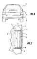
- a vehicle 10 such as an automobile, may employ a sensor 12, such as a radar sensor, to detect objects, such as other vehicles, in the area proximate a left side and a left rear side of the vehicle 10.
- Figure 2 depicts a location of a sensor 12 on the vehicle 10 such that objects, such as other vehicles, may be detected on a right side and a right rear side of the vehicle 10.
- the sensor 12 is depicted in a lower area of the vehicle 10 behind a body fascia panel 14, such as the rear bumper body fascia panel 14. With the sensor 12 positioned or mounted in such a location on the vehicle 10, proper sensing of surrounding objects, such as an adjacent vehicle(s), may be performed, as depicted in Figure 3 .
- a vehicle 10 is depicted with multiple radar sensors, such as radar sensors 12, installed on each side of the vehicle 10 as initially depicted in Figures 1 and 2 .
- Figure 3 further depicts a different vehicle 16 next to and slightly behind the sensor-equipped vehicle 10. Because the sensing vehicle 10 is equipped with at least one of the sensors 12, the driver of the vehicle 10 may be alerted to the other vehicle 16, which is within a close proximity to the vehicle 10 and potentially in a blind spot of the driver of the vehicle 10. To detect the vehicle 16, the sensor 12 of the vehicle 10 transmits, as an example, a radar signal.
- radar sensors exhibit an advantage that they can be integrated behind a vehicle bumper 18 and thus remain unseen to an observer standing beside the rear bumper 18, which contributes to the design aesthetics of the vehicle 10.
- radar sensors 12 In contrast to the limited range of infrared technology, whose sensors may be seen resident in a vehicle bumper from the exterior of the bumper, radar sensors 12 have a range of between a few centimeters and up to 30 meters, in one example of an automotive application.
- Another advantage is that radar sensors are not affected by the influences of weather, unlike infrared systems.
- the high accuracy and resolution of radar sensors allow them to be used in applications related to safety.
- detection areas 20, 22 are depicted as representative areas within which a sensor 12 may be effective at detecting a vehicle 16, which may be approaching the vehicle 10.
- a sensor 12 may be effective at detecting a vehicle 16, which may be approaching the vehicle 10.
- the driver of the vehicle 10 will not be burdened with turning his or her head in an attempt to visually check an area that may be known as a "blind spot" to a driver of a vehicle 10.
- a multiple lane situation such as a three lane or greater road, if the vehicle 10 is traveling along an interior lane, vehicles approaching on either side of the vehicle 10 may be simultaneously detected.
- Figure 4 depicts the general location of the sensor 12 in vehicle 10 from a macro perspective while Figure 5 depicts an enlarged top view of the sensor 12 in a mounted position.
- a sensor 12 that is retained within a bracket 24 that may mount to the vehicle underbody 48, and more specifically, the bracket 24 may be a framework or solid structure that is configured to define a pocket 26 within which the sensor 12 may reside.
- the bracket 24 may be elongated, meaning the bracket may have one dimension, such as a length, that is longer than the other two, such as the thickness and width.
- the sensor 12 may fit into the bracket 24.
- the sensor 12 may drop in from the top of the bracket 24 or either end of the bracket 24, that is, in the for-aft direction of the vehicle.
- the bracket 24, framework, or solid structure may further define a slot or groove 28, within which a projection 30 of the body fascia panel 14 may fit into to securely hold the body fascia panel 14.
- the slot or groove 28 may be along the length of the bracket 24, as opposed to the width or height.
- the body fascia panel 14, also known simply as fascia 14, may be a molded plastic or fiberglass and have at least projection 30 molded directly into a rear side of the fascia 14.
- the projection 30 may be a separate piece and be joined to the fascia 14 by an adhesive, a heating and joining process or a fastener that passes through or into the fascia 14.
- a fastener may pass from the exterior of the fascia 14, and into the projection 30 to secure the projection to the fascia 14.
- the projection 30 may be secured to the fascia with a fastener that passes from the inside of the fascia, first through the projection 30 and then into the fascia 14.
- the projection 30 may then be successfully pressed into the slot 28 to secure the fascia 14 to the bracket 24.
- the slot 28 may be viewed as the front slot, while the slot 34 may be viewed as the rear slot, keeping with the for-aft orientation of the vehicle 10.
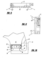
- Figure 6 depicts a vehicle 10 in which the sensor 12, which may be the same sensor as depicted in Figures 4 and 5 , is situated behind the bumper fascia 14. Because Figure 7 is a view from the rear, the bracket 24 defines a top slot 36 and a bottom slot 38, using the ground on which the vehicle is resting as a reference. Similar to the structure described in Figure 5 , the fascia panel 14 has a projection 40, considered a top projection 40 for ease of reference, which fits into a top slot 36, and a projection 42, considered a bottom projection 42 for ease of reference, that fits into a bottom slot 38.
- the projections 40, 42 may be integrally molded into the fascia 14, which may be a plastic or fiberglass material.
- the projections 40, 42 may be fastened to the fascia 14 using traditional fasteners, such as screws that originate from either the exterior or the interior of the fascia 14 and screw into both, the fascia 14 and either of the projections 40, 42.
- the sensor 12 may slide into the pocket 44 or receptacle 44 defined by the bracket 24 or framework 24.
- the bracket 24 may instead be replaced with a solid structure, such as plastic, and have a receptacle or pocket 44 molded directly into the solid structure.
- top slot 36 and bottom slot 38 may be molded directly into such a solid plastic structure.
- the bracket 24 of Figures 5 and 7 may mount to a vehicle underbody 48 with traditional fasteners such as screws or bolts. Additionally, if the bracket 24 is constructed as a frame-like structure, it may be made from a metal or a plastic.
- Figure 8 is a top view of a representative radar sensor 12 depicting an angular range of radar detection as viewed from above the sensor 12, while Figure 9 is a rear view of the representative radar sensor 12 depicting an angular range of radar detection if viewed from a front or rear of the sensor 12 or vehicle 10 within which the sensor is mounted.
- the radar sensor 12 depicted in Figures 8 and 9 is but one example of the angular range of a radar detector that may be used in the vehicle 10 to detect surrounding vehicle(s), as depicted in Figure 3 .
- vehicles entering the blind spot area 46 which encompasses the radar detection area of the radar sensor 12, will be detected and alert the driver of an equipped vehicle to such detection.
- Figure 10 is a left side view of a rear of a vehicle. More specifically, the sensor 12 lies within a pocket or receptacle 60 formed as part of or within the frame-like or solid bracket 24.
- the pocket or receptacle 60 may be rectangular or approximately rectangular, such as with rounded interior corners.
- the manufacturing process used to make the bracket may dictate whether sharp interior corners or rounded interior corners, for example, are manufactured into the bracket 24.
- the bracket 24 may be secured to the vehicle or vehicle underbody 48 using fasteners 50, 52, 54, 56 while the fascia 14 fits into a slot 58 on the bracket 24, as described in conjunction with Figures 5 and 7 .
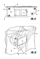
- Figure 11 depicts an enlarged view of the bracket 24 that defines a pocket within which the sensor 12 resides.
- a slot 58 receives a projection or length of fascia edge 62 ( Figure 10 ) to secure the fascia 14 to the bracket 24.
- the bracket 24 serves the dual purpose of retaining the sensor 12 and the fascia 14.
- the body fascia panel 14 can be seen located in front of the vehicle underbody 48, or in other words, the underbody 48 is behind the body fascia panel 14. More specifically, attached to as a separate piece, or molded directly into the body fascia panel 14 is an extension piece of material that functions as a sensor support 64 within which the sensor 12 resides. As depicted, the sensor support 64 may be a strand-like structure molded into the body fascia panel 14. Alternatively the sensor support 64 may be a solid structure, as opposed to the strand-like structure, which has a material and a weight-saving advantage associated with it.
- the sensor support 64 defines a sensor pocket 66 within which the sensor 12 slides into and resides for subsequent use.
- a mounting support 68 lies on a side of the sensor 12 opposite to the sensor support 64.
- the mounting support 68 may have a fastener area 70 through a hole 72 of which a fastener may pass.
- the fastener area 70 may form a complete circle to prevent a fastener from losing its grip or fastening force.
- the fastener area 70 may be semi-circular to ease in connection of the sensor support 64 and mounting support 68 to the fastener.
- the mounting support 68 may be a structure formed of strands of material as in a framework, or a solid structure, the former having greater material and weight-saving advantages than the latter.
- the sensor pocket 66 is formed in part by the mounting support 68 and the sensor support 64. Stated another way, the sensor support 64 and the mounting support 68 bound the sensor pocket 66 and help to define the pocket 66.
- the embodiment of Figure 12 has the advantage of incorporating a radar sensor 12 into a molded pocket 66 of a structure.
- the structure takes the form of a sensor support 64 and a mounting support 68 that are designed to secure the sensor 12 but also is the body fascia panel 14. Thus, a single structure may serve multiple functions.
- Figure 13 depicts the embodiment of Figure 12 with a seal or sealant 74 surrounding the sensor 12.
- the seal or sealant 74 may be a foam, rubber or plastic material that may be installed around the sensor 12 to seal the sensor 12 to the inside surface of the fascia and protect the sensor 12 from dust, dirt, water and debris that the sensor 12 may be subjected to in its potential installation locations, such as in a lower fascia panel location near a road surface.
- the bracket 24 is capable of retaining a sensor 12 and a body fascia panel 14.
- the bracket 24 may be manufactured from a metal, such as steel, aluminum or magnesium.
- the bracket 24 may be manufactured from a plastic to provide advantages related to weight, rust and corrosion, and manufacturing costs.
- the fascia panel 14 may be installed into the bracket 24 after the bracket 24 is fastened to a vehicle underbody structure 48.
- Figure 10 depicts such a fastening.
- the bracket 24 may be integrally molded to the fascia 14 as part of the fascia 14 such that no separate connection between the bracket 24 and the fascia 14 is necessary to hold the bracket 24 to the fascia 14.
- Figure 12 depicts the advantage of having the sensor support 64 integrally molded into or as part of the fascia 14.
- the embodiment depicted in Figure 12 may be located in a lower location of the fascia behind a rear wheel of a vehicle, as depicted in Figures 1 and 2 .
- An additional advantage is that parts that may have previously been separate, such as a radar sensor bracket and a fascia mounting bracket, may in part be eliminated.
- a dual use part such as the single piece as best depicted in Figures 5 , 7 , and 10-13 , eliminates multiple, separate parts.
- the radar sensor pocket 66 into the fascia sensor support 64 and fascia 14, as depicted in at least Figure 12 , the sensor 12 may be properly aligned upon installation of the fascia 14 onto a vehicle 10. That is, proper sensor alignment is molded into the fascia 14 and sensor pocket 66, and thus, no subsequent, post-installation alignment is required. Finally, because all vehicles have body fascia panels, the present invention may be incorporated into nearly every vehicle in which radar sensors are required.
Landscapes
- Engineering & Computer Science (AREA)
- Radar, Positioning & Navigation (AREA)
- Remote Sensing (AREA)
- Physics & Mathematics (AREA)
- Electromagnetism (AREA)
- Computer Networks & Wireless Communication (AREA)
- General Physics & Mathematics (AREA)
- Mechanical Engineering (AREA)
- Radar Systems Or Details Thereof (AREA)
Applications Claiming Priority (1)
| Application Number | Priority Date | Filing Date | Title |
|---|---|---|---|
| US11/766,142 US20080315050A1 (en) | 2007-06-21 | 2007-06-21 | Vehicle blind spot radar sensor mount |
Publications (2)
| Publication Number | Publication Date |
|---|---|
| EP2006162A1 true EP2006162A1 (de) | 2008-12-24 |
| EP2006162B1 EP2006162B1 (de) | 2011-01-26 |
Family
ID=39790903
Family Applications (1)
| Application Number | Title | Priority Date | Filing Date |
|---|---|---|---|
| EP08009720A Ceased EP2006162B1 (de) | 2007-06-21 | 2008-05-28 | Radarsensormontage für den toten Winkel von Fahrzeugen |
Country Status (3)
| Country | Link |
|---|---|
| US (1) | US20080315050A1 (de) |
| EP (1) | EP2006162B1 (de) |
| DE (1) | DE602008004692D1 (de) |
Cited By (5)
| Publication number | Priority date | Publication date | Assignee | Title |
|---|---|---|---|---|
| AT512819A2 (de) * | 2012-04-19 | 2013-11-15 | Kmt Kunststoff Metalltechnik Gmbh | Vorrichtung und Verfahren zum Spritzgießen einer Ummantelung eines Bauteils |
| WO2015072289A1 (ja) * | 2013-11-14 | 2015-05-21 | オートリブ ディベロップメント エービー | 車載用レーダ設置構造およびフェイシアリテーナ |
| EP3164734A1 (de) * | 2014-07-02 | 2017-05-10 | Robert Bosch GmbH | Fahrzeugteil mit integriertem sensor und verfahren zu dessen herstellung |
| US10399522B2 (en) | 2016-12-12 | 2019-09-03 | Toyota Jidosha Kabushiki Kaisha | Mounting structure of vehicle periphery monitoring device |
| CN110277632A (zh) * | 2018-03-13 | 2019-09-24 | 松下知识产权经营株式会社 | 天线装置 |
Families Citing this family (21)
| Publication number | Priority date | Publication date | Assignee | Title |
|---|---|---|---|---|
| US7988212B2 (en) * | 2007-01-25 | 2011-08-02 | Ford Motor Company | Vehicle mounting and alignment bracket |
| JP2012122936A (ja) | 2010-12-10 | 2012-06-28 | Panasonic Corp | 超音波センサ |
| US8690206B1 (en) | 2012-10-04 | 2014-04-08 | Toyota Motor Engineering & Manufacturing North America, Inc. | Integrated stone and water shield for blind spot monitor |
| US9132791B2 (en) * | 2012-10-19 | 2015-09-15 | Toyota Motor Engineering & Manufacturing North America, Inc. | Blind spot monitor assembly |
| WO2015045849A1 (ja) * | 2013-09-27 | 2015-04-02 | オートリブ ディベロップメント エービー | 車載用レーダ装置 |
| US9278659B2 (en) | 2014-04-22 | 2016-03-08 | Ford Global Technologies, Llc | Bumper component with embedded sensor |
| JP6790342B2 (ja) * | 2015-10-02 | 2020-11-25 | トヨタ自動車株式会社 | 車両用センサの取り付け構造 |
| US20170210307A1 (en) * | 2016-01-22 | 2017-07-27 | Toyota Motor Engineering & Manufacturing North America, Inc. | Attachment for electrical components |
| JP6344424B2 (ja) * | 2016-04-19 | 2018-06-20 | トヨタ自動車株式会社 | 周辺情報検出センサの取付構造 |
| US9925920B2 (en) | 2016-05-24 | 2018-03-27 | Ford Global Technologies, Llc | Extended lane blind spot detection |
| DE102016116701B4 (de) * | 2016-09-07 | 2024-09-12 | Dr. Ing. H.C. F. Porsche Aktiengesellschaft | Seitenbauteil und Fahrzeug mit einem Seitenbauteil |
| US10160292B2 (en) | 2017-02-16 | 2018-12-25 | Honda Motor Co., Ltd. | Underbody cover assembly |
| JP6754403B2 (ja) * | 2018-08-24 | 2020-09-09 | 本田技研工業株式会社 | 外界センサ |
| JP6754402B2 (ja) * | 2018-08-24 | 2020-09-09 | 本田技研工業株式会社 | 外界センサ |
| US10710534B2 (en) | 2018-09-11 | 2020-07-14 | Volvo Car Corporation | Flexing radar bracket in bumper |
| DE102018216784B4 (de) * | 2018-09-28 | 2025-08-07 | Continental Autonomous Mobility Germany GmbH | Sensoranordnung für ein Fahrzeug und Fahrzeug |
| JP6960389B2 (ja) * | 2018-12-04 | 2021-11-05 | 本田技研工業株式会社 | 検出装置および車両 |
| US10967913B2 (en) | 2019-08-28 | 2021-04-06 | Ford Global Technologies, Llc | Detachable quarter panel bracket |
| JP7312376B2 (ja) * | 2019-09-02 | 2023-07-21 | スズキ株式会社 | 車両用センサ取付構造 |
| US11447199B2 (en) | 2020-02-21 | 2022-09-20 | Toyota Motor Engineering & Manufacturing North America, Inc. | Guard for vehicle blind spot monitor |
| JP2022158504A (ja) * | 2021-04-02 | 2022-10-17 | トヨタ自動車株式会社 | 車両構造 |
Citations (7)
| Publication number | Priority date | Publication date | Assignee | Title |
|---|---|---|---|---|
| JPS5939193A (ja) * | 1982-08-27 | 1984-03-03 | Nippon Soken Inc | 超音波送受波器 |
| DE19626291A1 (de) * | 1996-07-01 | 1998-01-08 | Teves Gmbh Alfred | Befestigungshülse für Ultraschallwandler mit selbstsichernder Befestigung |
| JPH1044891A (ja) * | 1996-07-30 | 1998-02-17 | Niles Parts Co Ltd | 障害物検出装置の取付構造 |
| DE19819698A1 (de) * | 1998-05-02 | 1999-11-11 | Daimler Chrysler Ag | Befestigungseinrichtung an einem Anbauteil für ein Kraftfahrzeug |
| JP2000085497A (ja) * | 1998-09-08 | 2000-03-28 | Mazda Motor Corp | 車両の電装品配設構造 |
| US20060021440A1 (en) * | 2004-08-02 | 2006-02-02 | Denso Corporation | Ultrasonic sensor assembly |
| JP2006199145A (ja) * | 2005-01-20 | 2006-08-03 | Toyota Motor Corp | バンパのセンサー取付構造 |
Family Cites Families (8)
| Publication number | Priority date | Publication date | Assignee | Title |
|---|---|---|---|---|
| US4538038A (en) * | 1983-11-09 | 1985-08-27 | Westcode, Inc. | Door panel position sensor assembly |
| JP3536967B2 (ja) * | 1998-03-09 | 2004-06-14 | 矢崎総業株式会社 | メータの取付構造およびメータ取付方法 |
| DE19940678A1 (de) * | 1998-08-28 | 2000-05-25 | Toyoda Automatic Loom Works | Montagestruktur für einen Sensor in einem Industriefahrzeug und Industriefahrzeug |
| GB0005312D0 (en) * | 2000-02-28 | 2000-04-26 | Britax Wingard Ltd | Mounting for proximity radar |
| US6460648B2 (en) * | 2001-01-08 | 2002-10-08 | General Motors Corporation | Impact sensor assembly for an automotive vehicle and a method of forming the same |
| JP3960459B2 (ja) * | 2001-03-12 | 2007-08-15 | 本田技研工業株式会社 | 測距センサの取付け構造 |
| DE10118112A1 (de) * | 2001-04-11 | 2002-10-17 | Dynamit Nobel Kunststoff Gmbh | Halter für ein Bauteil mit geringen Abmessungen an einem Stoßfänger |
| CA2550288C (en) * | 2003-09-04 | 2013-02-05 | William D. Blake | Fascia for motor vehicle with integral component mounting and a method of making the same |
-
2007
- 2007-06-21 US US11/766,142 patent/US20080315050A1/en not_active Abandoned
-
2008
- 2008-05-28 DE DE602008004692T patent/DE602008004692D1/de active Active
- 2008-05-28 EP EP08009720A patent/EP2006162B1/de not_active Ceased
Patent Citations (7)
| Publication number | Priority date | Publication date | Assignee | Title |
|---|---|---|---|---|
| JPS5939193A (ja) * | 1982-08-27 | 1984-03-03 | Nippon Soken Inc | 超音波送受波器 |
| DE19626291A1 (de) * | 1996-07-01 | 1998-01-08 | Teves Gmbh Alfred | Befestigungshülse für Ultraschallwandler mit selbstsichernder Befestigung |
| JPH1044891A (ja) * | 1996-07-30 | 1998-02-17 | Niles Parts Co Ltd | 障害物検出装置の取付構造 |
| DE19819698A1 (de) * | 1998-05-02 | 1999-11-11 | Daimler Chrysler Ag | Befestigungseinrichtung an einem Anbauteil für ein Kraftfahrzeug |
| JP2000085497A (ja) * | 1998-09-08 | 2000-03-28 | Mazda Motor Corp | 車両の電装品配設構造 |
| US20060021440A1 (en) * | 2004-08-02 | 2006-02-02 | Denso Corporation | Ultrasonic sensor assembly |
| JP2006199145A (ja) * | 2005-01-20 | 2006-08-03 | Toyota Motor Corp | バンパのセンサー取付構造 |
Cited By (12)
| Publication number | Priority date | Publication date | Assignee | Title |
|---|---|---|---|---|
| AT512819A2 (de) * | 2012-04-19 | 2013-11-15 | Kmt Kunststoff Metalltechnik Gmbh | Vorrichtung und Verfahren zum Spritzgießen einer Ummantelung eines Bauteils |
| AT512819A3 (de) * | 2012-04-19 | 2015-01-15 | Kmt Kunststoff Metalltechnik Gmbh | Vorrichtung und Verfahren zum Spritzgießen einer Ummantelung eines Bauteils |
| AT512819B1 (de) * | 2012-04-19 | 2015-03-15 | Kmt Kunststoff Metalltechnik Gmbh | Vorrichtung und Verfahren zum Spritzgießen einer Ummantelung eines Bauteils |
| WO2015072289A1 (ja) * | 2013-11-14 | 2015-05-21 | オートリブ ディベロップメント エービー | 車載用レーダ設置構造およびフェイシアリテーナ |
| CN105723235A (zh) * | 2013-11-14 | 2016-06-29 | 奥托立夫开发公司 | 车载用雷达设置结构和面板固定件 |
| JPWO2015072289A1 (ja) * | 2013-11-14 | 2017-03-16 | オートリブ ディベロップメント エービー | 車載用レーダ設置構造およびフェイシアリテーナ |
| EP3070489A4 (de) * | 2013-11-14 | 2017-06-21 | Autoliv Development AB | Installationsstruktur für fahrzeugradar und armaturenbretthalter |
| US9804261B2 (en) | 2013-11-14 | 2017-10-31 | Autoliv Development Ab | Vehicle radar installation structure and fascia retainer |
| CN105723235B (zh) * | 2013-11-14 | 2019-03-26 | 维宁尔瑞典公司 | 车载用雷达设置结构和面板固定件 |
| EP3164734A1 (de) * | 2014-07-02 | 2017-05-10 | Robert Bosch GmbH | Fahrzeugteil mit integriertem sensor und verfahren zu dessen herstellung |
| US10399522B2 (en) | 2016-12-12 | 2019-09-03 | Toyota Jidosha Kabushiki Kaisha | Mounting structure of vehicle periphery monitoring device |
| CN110277632A (zh) * | 2018-03-13 | 2019-09-24 | 松下知识产权经营株式会社 | 天线装置 |
Also Published As
| Publication number | Publication date |
|---|---|
| DE602008004692D1 (de) | 2011-03-10 |
| US20080315050A1 (en) | 2008-12-25 |
| EP2006162B1 (de) | 2011-01-26 |
Similar Documents
| Publication | Publication Date | Title |
|---|---|---|
| EP2006162B1 (de) | Radarsensormontage für den toten Winkel von Fahrzeugen | |
| US9132791B2 (en) | Blind spot monitor assembly | |
| US10024970B2 (en) | Sensor housing assembly for attachment to a motor vehicle | |
| US7911331B2 (en) | Collision detector | |
| JP6842512B2 (ja) | 車体の後部構造 | |
| EP3333023B1 (de) | Montagestruktur einer fahrzeugumfeldüberwachungsvorrichtung | |
| EP3150445A1 (de) | Vorderteilkonstruktion eines fahrzeuges mit sensor zur detektion einer fussgängerkollision | |
| RU147025U1 (ru) | Элемент облицовки автомобиля с датчиком удара | |
| US8505943B2 (en) | Cantilevered, vehicle side mount safety guard | |
| US9187138B2 (en) | Roof spoiler mounting system | |
| US8910986B1 (en) | Bonded and rotatable vehicle sensor assembly | |
| RU150713U1 (ru) | Элемент облицовки транспортного средства с блоком датчика удара | |
| US10882564B2 (en) | Wheel housing liner assembly | |
| US8690206B1 (en) | Integrated stone and water shield for blind spot monitor | |
| US9114769B1 (en) | Vehicle sensor assembly with lever assist | |
| TR201609940A2 (tr) | Bi̇r gösterge paneli̇ne sahi̇p motorlu araç | |
| US8608214B2 (en) | Bumper mounted plate for auxiliary lights | |
| US7537243B1 (en) | Mud flap retrofit kit and method of use | |
| CN116533890A (zh) | 激光雷达支架和车辆 | |
| EP3524475A1 (de) | Trittstufensystem mit schutzschild | |
| US8720978B2 (en) | Motor vehicle body | |
| RU2042553C1 (ru) | Щиток колесной ниши автомобиля | |
| JP5206857B2 (ja) | 車両用衝撃センサの取付構造 | |
| US8733826B1 (en) | Truck bed panel attached to door hinge mounting plate | |
| EP4016120A1 (de) | Lidar-sensorbaugruppe und halterung |
Legal Events
| Date | Code | Title | Description |
|---|---|---|---|
| PUAI | Public reference made under article 153(3) epc to a published international application that has entered the european phase |
Free format text: ORIGINAL CODE: 0009012 |
|
| AK | Designated contracting states |
Kind code of ref document: A1 Designated state(s): AT BE BG CH CY CZ DE DK EE ES FI FR GB GR HR HU IE IS IT LI LT LU LV MC MT NL NO PL PT RO SE SI SK TR |
|
| AX | Request for extension of the european patent |
Extension state: AL BA MK RS |
|
| 17P | Request for examination filed |
Effective date: 20090612 |
|
| 17Q | First examination report despatched |
Effective date: 20090710 |
|
| AKX | Designation fees paid |
Designated state(s): DE FR GB |
|
| RAP1 | Party data changed (applicant data changed or rights of an application transferred) |
Owner name: CHRYSLER GROUP LLC |
|
| GRAJ | Information related to disapproval of communication of intention to grant by the applicant or resumption of examination proceedings by the epo deleted |
Free format text: ORIGINAL CODE: EPIDOSDIGR1 |
|
| GRAP | Despatch of communication of intention to grant a patent |
Free format text: ORIGINAL CODE: EPIDOSNIGR1 |
|
| GRAP | Despatch of communication of intention to grant a patent |
Free format text: ORIGINAL CODE: EPIDOSNIGR1 |
|
| GRAS | Grant fee paid |
Free format text: ORIGINAL CODE: EPIDOSNIGR3 |
|
| GRAA | (expected) grant |
Free format text: ORIGINAL CODE: 0009210 |
|
| AK | Designated contracting states |
Kind code of ref document: B1 Designated state(s): DE FR GB |
|
| REG | Reference to a national code |
Ref country code: GB Ref legal event code: FG4D |
|
| REF | Corresponds to: |
Ref document number: 602008004692 Country of ref document: DE Date of ref document: 20110310 Kind code of ref document: P |
|
| REG | Reference to a national code |
Ref country code: DE Ref legal event code: R096 Ref document number: 602008004692 Country of ref document: DE Effective date: 20110310 |
|
| PLBE | No opposition filed within time limit |
Free format text: ORIGINAL CODE: 0009261 |
|
| STAA | Information on the status of an ep patent application or granted ep patent |
Free format text: STATUS: NO OPPOSITION FILED WITHIN TIME LIMIT |
|
| 26N | No opposition filed |
Effective date: 20111027 |
|
| REG | Reference to a national code |
Ref country code: DE Ref legal event code: R097 Ref document number: 602008004692 Country of ref document: DE Effective date: 20111027 |
|
| REG | Reference to a national code |
Ref country code: FR Ref legal event code: PLFP Year of fee payment: 9 |
|
| REG | Reference to a national code |
Ref country code: FR Ref legal event code: PLFP Year of fee payment: 10 |
|
| REG | Reference to a national code |
Ref country code: FR Ref legal event code: PLFP Year of fee payment: 11 |
|
| PGFP | Annual fee paid to national office [announced via postgrant information from national office to epo] |
Ref country code: DE Payment date: 20210527 Year of fee payment: 14 Ref country code: FR Payment date: 20210525 Year of fee payment: 14 |
|
| PGFP | Annual fee paid to national office [announced via postgrant information from national office to epo] |
Ref country code: GB Payment date: 20210527 Year of fee payment: 14 |
|
| REG | Reference to a national code |
Ref country code: DE Ref legal event code: R119 Ref document number: 602008004692 Country of ref document: DE |
|
| GBPC | Gb: european patent ceased through non-payment of renewal fee |
Effective date: 20220528 |
|
| PG25 | Lapsed in a contracting state [announced via postgrant information from national office to epo] |
Ref country code: FR Free format text: LAPSE BECAUSE OF NON-PAYMENT OF DUE FEES Effective date: 20220531 |
|
| PG25 | Lapsed in a contracting state [announced via postgrant information from national office to epo] |
Ref country code: GB Free format text: LAPSE BECAUSE OF NON-PAYMENT OF DUE FEES Effective date: 20220528 Ref country code: DE Free format text: LAPSE BECAUSE OF NON-PAYMENT OF DUE FEES Effective date: 20221201 |