EP2006266B1 - Herstellungsverfahren einer wabenstruktur - Google Patents
Herstellungsverfahren einer wabenstruktur Download PDFInfo
- Publication number
- EP2006266B1 EP2006266B1 EP07739549.9A EP07739549A EP2006266B1 EP 2006266 B1 EP2006266 B1 EP 2006266B1 EP 07739549 A EP07739549 A EP 07739549A EP 2006266 B1 EP2006266 B1 EP 2006266B1
- Authority
- EP
- European Patent Office
- Prior art keywords
- bonding
- honeycomb
- honeycomb structure
- bonding material
- bonded
- Prior art date
- Legal status (The legal status is an assumption and is not a legal conclusion. Google has not performed a legal analysis and makes no representation as to the accuracy of the status listed.)
- Ceased
Links
Images

Classifications
-
- C—CHEMISTRY; METALLURGY
- C04—CEMENTS; CONCRETE; ARTIFICIAL STONE; CERAMICS; REFRACTORIES
- C04B—LIME, MAGNESIA; SLAG; CEMENTS; COMPOSITIONS THEREOF, e.g. MORTARS, CONCRETE OR LIKE BUILDING MATERIALS; ARTIFICIAL STONE; CERAMICS; REFRACTORIES; TREATMENT OF NATURAL STONE
- C04B38/00—Porous mortars, concrete, artificial stone or ceramic ware; Preparation thereof
- C04B38/0006—Honeycomb structures
- C04B38/0009—Honeycomb structures characterised by features relating to the cell walls, e.g. wall thickness or distribution of pores in the walls
-
- B—PERFORMING OPERATIONS; TRANSPORTING
- B01—PHYSICAL OR CHEMICAL PROCESSES OR APPARATUS IN GENERAL
- B01D—SEPARATION
- B01D39/00—Filtering material for liquid or gaseous fluids
-
- C—CHEMISTRY; METALLURGY
- C04—CEMENTS; CONCRETE; ARTIFICIAL STONE; CERAMICS; REFRACTORIES
- C04B—LIME, MAGNESIA; SLAG; CEMENTS; COMPOSITIONS THEREOF, e.g. MORTARS, CONCRETE OR LIKE BUILDING MATERIALS; ARTIFICIAL STONE; CERAMICS; REFRACTORIES; TREATMENT OF NATURAL STONE
- C04B35/00—Shaped ceramic products characterised by their composition; Ceramics compositions; Processing powders of inorganic compounds preparatory to the manufacturing of ceramic products
- C04B35/515—Shaped ceramic products characterised by their composition; Ceramics compositions; Processing powders of inorganic compounds preparatory to the manufacturing of ceramic products based on non-oxide ceramics
- C04B35/56—Shaped ceramic products characterised by their composition; Ceramics compositions; Processing powders of inorganic compounds preparatory to the manufacturing of ceramic products based on non-oxide ceramics based on carbides or oxycarbides
- C04B35/565—Shaped ceramic products characterised by their composition; Ceramics compositions; Processing powders of inorganic compounds preparatory to the manufacturing of ceramic products based on non-oxide ceramics based on carbides or oxycarbides based on silicon carbide
- C04B35/573—Shaped ceramic products characterised by their composition; Ceramics compositions; Processing powders of inorganic compounds preparatory to the manufacturing of ceramic products based on non-oxide ceramics based on carbides or oxycarbides based on silicon carbide obtained by reaction sintering or recrystallisation
-
- C—CHEMISTRY; METALLURGY
- C04—CEMENTS; CONCRETE; ARTIFICIAL STONE; CERAMICS; REFRACTORIES
- C04B—LIME, MAGNESIA; SLAG; CEMENTS; COMPOSITIONS THEREOF, e.g. MORTARS, CONCRETE OR LIKE BUILDING MATERIALS; ARTIFICIAL STONE; CERAMICS; REFRACTORIES; TREATMENT OF NATURAL STONE
- C04B35/00—Shaped ceramic products characterised by their composition; Ceramics compositions; Processing powders of inorganic compounds preparatory to the manufacturing of ceramic products
- C04B35/622—Forming processes; Processing powders of inorganic compounds preparatory to the manufacturing of ceramic products
- C04B35/626—Preparing or treating the powders individually or as batches ; preparing or treating macroscopic reinforcing agents for ceramic products, e.g. fibres; mechanical aspects section B
- C04B35/63—Preparing or treating the powders individually or as batches ; preparing or treating macroscopic reinforcing agents for ceramic products, e.g. fibres; mechanical aspects section B using additives specially adapted for forming the products, e.g.. binder binders
- C04B35/632—Organic additives
- C04B35/636—Polysaccharides or derivatives thereof
- C04B35/6365—Cellulose or derivatives thereof
-
- C—CHEMISTRY; METALLURGY
- C04—CEMENTS; CONCRETE; ARTIFICIAL STONE; CERAMICS; REFRACTORIES
- C04B—LIME, MAGNESIA; SLAG; CEMENTS; COMPOSITIONS THEREOF, e.g. MORTARS, CONCRETE OR LIKE BUILDING MATERIALS; ARTIFICIAL STONE; CERAMICS; REFRACTORIES; TREATMENT OF NATURAL STONE
- C04B37/00—Joining burned ceramic articles with other burned ceramic articles or other articles by heating
-
- C—CHEMISTRY; METALLURGY
- C04—CEMENTS; CONCRETE; ARTIFICIAL STONE; CERAMICS; REFRACTORIES
- C04B—LIME, MAGNESIA; SLAG; CEMENTS; COMPOSITIONS THEREOF, e.g. MORTARS, CONCRETE OR LIKE BUILDING MATERIALS; ARTIFICIAL STONE; CERAMICS; REFRACTORIES; TREATMENT OF NATURAL STONE
- C04B37/00—Joining burned ceramic articles with other burned ceramic articles or other articles by heating
- C04B37/003—Joining burned ceramic articles with other burned ceramic articles or other articles by heating by means of an interlayer consisting of a combination of materials selected from glass, or ceramic material with metals, metal oxides or metal salts
- C04B37/005—Joining burned ceramic articles with other burned ceramic articles or other articles by heating by means of an interlayer consisting of a combination of materials selected from glass, or ceramic material with metals, metal oxides or metal salts consisting of glass or ceramic material
-
- C—CHEMISTRY; METALLURGY
- C04—CEMENTS; CONCRETE; ARTIFICIAL STONE; CERAMICS; REFRACTORIES
- C04B—LIME, MAGNESIA; SLAG; CEMENTS; COMPOSITIONS THEREOF, e.g. MORTARS, CONCRETE OR LIKE BUILDING MATERIALS; ARTIFICIAL STONE; CERAMICS; REFRACTORIES; TREATMENT OF NATURAL STONE
- C04B37/00—Joining burned ceramic articles with other burned ceramic articles or other articles by heating
- C04B37/008—Joining burned ceramic articles with other burned ceramic articles or other articles by heating by means of an interlayer consisting of an organic adhesive, e.g. phenol resin or pitch
-
- F—MECHANICAL ENGINEERING; LIGHTING; HEATING; WEAPONS; BLASTING
- F01—MACHINES OR ENGINES IN GENERAL; ENGINE PLANTS IN GENERAL; STEAM ENGINES
- F01N—GAS-FLOW SILENCERS OR EXHAUST APPARATUS FOR MACHINES OR ENGINES IN GENERAL; GAS-FLOW SILENCERS OR EXHAUST APPARATUS FOR INTERNAL-COMBUSTION ENGINES
- F01N3/00—Exhaust or silencing apparatus having means for purifying, rendering innocuous, or otherwise treating exhaust
- F01N3/08—Exhaust or silencing apparatus having means for purifying, rendering innocuous, or otherwise treating exhaust for rendering innocuous
- F01N3/10—Exhaust or silencing apparatus having means for purifying, rendering innocuous, or otherwise treating exhaust for rendering innocuous by thermal or catalytic conversion of noxious components of exhaust
- F01N3/24—Exhaust or silencing apparatus having means for purifying, rendering innocuous, or otherwise treating exhaust for rendering innocuous by thermal or catalytic conversion of noxious components of exhaust characterised by constructional aspects of converting apparatus
- F01N3/28—Construction of catalytic reactors
- F01N3/2839—Arrangements for mounting catalyst support in housing, e.g. with means for compensating thermal expansion or vibration
- F01N3/2842—Arrangements for mounting catalyst support in housing, e.g. with means for compensating thermal expansion or vibration specially adapted for monolithic supports, e.g. of honeycomb type
-
- B—PERFORMING OPERATIONS; TRANSPORTING
- B01—PHYSICAL OR CHEMICAL PROCESSES OR APPARATUS IN GENERAL
- B01D—SEPARATION
- B01D2239/00—Aspects relating to filtering material for liquid or gaseous fluids
- B01D2239/08—Special characteristics of binders
-
- B—PERFORMING OPERATIONS; TRANSPORTING
- B01—PHYSICAL OR CHEMICAL PROCESSES OR APPARATUS IN GENERAL
- B01J—CHEMICAL OR PHYSICAL PROCESSES, e.g. CATALYSIS OR COLLOID CHEMISTRY; THEIR RELEVANT APPARATUS
- B01J35/00—Catalysts, in general, characterised by their form or physical properties
- B01J35/50—Catalysts, in general, characterised by their form or physical properties characterised by their shape or configuration
- B01J35/56—Foraminous structures having flow-through passages or channels, e.g. grids or three-dimensional [3D] monoliths
- B01J35/57—Honeycombs
-
- C—CHEMISTRY; METALLURGY
- C04—CEMENTS; CONCRETE; ARTIFICIAL STONE; CERAMICS; REFRACTORIES
- C04B—LIME, MAGNESIA; SLAG; CEMENTS; COMPOSITIONS THEREOF, e.g. MORTARS, CONCRETE OR LIKE BUILDING MATERIALS; ARTIFICIAL STONE; CERAMICS; REFRACTORIES; TREATMENT OF NATURAL STONE
- C04B2235/00—Aspects relating to ceramic starting mixtures or sintered ceramic products
- C04B2235/02—Composition of constituents of the starting material or of secondary phases of the final product
- C04B2235/30—Constituents and secondary phases not being of a fibrous nature
- C04B2235/34—Non-metal oxides, non-metal mixed oxides, or salts thereof that form the non-metal oxides upon heating, e.g. carbonates, nitrates, (oxy)hydroxides, chlorides
- C04B2235/3418—Silicon oxide, silicic acids or oxide forming salts thereof, e.g. silica sol, fused silica, silica fume, cristobalite, quartz or flint
-
- C—CHEMISTRY; METALLURGY
- C04—CEMENTS; CONCRETE; ARTIFICIAL STONE; CERAMICS; REFRACTORIES
- C04B—LIME, MAGNESIA; SLAG; CEMENTS; COMPOSITIONS THEREOF, e.g. MORTARS, CONCRETE OR LIKE BUILDING MATERIALS; ARTIFICIAL STONE; CERAMICS; REFRACTORIES; TREATMENT OF NATURAL STONE
- C04B2235/00—Aspects relating to ceramic starting mixtures or sintered ceramic products
- C04B2235/02—Composition of constituents of the starting material or of secondary phases of the final product
- C04B2235/30—Constituents and secondary phases not being of a fibrous nature
- C04B2235/42—Non metallic elements added as constituents or additives, e.g. sulfur, phosphor, selenium or tellurium
- C04B2235/428—Silicon
-
- C—CHEMISTRY; METALLURGY
- C04—CEMENTS; CONCRETE; ARTIFICIAL STONE; CERAMICS; REFRACTORIES
- C04B—LIME, MAGNESIA; SLAG; CEMENTS; COMPOSITIONS THEREOF, e.g. MORTARS, CONCRETE OR LIKE BUILDING MATERIALS; ARTIFICIAL STONE; CERAMICS; REFRACTORIES; TREATMENT OF NATURAL STONE
- C04B2235/00—Aspects relating to ceramic starting mixtures or sintered ceramic products
- C04B2235/02—Composition of constituents of the starting material or of secondary phases of the final product
- C04B2235/30—Constituents and secondary phases not being of a fibrous nature
- C04B2235/48—Organic compounds becoming part of a ceramic after heat treatment, e.g. carbonising phenol resins
-
- C—CHEMISTRY; METALLURGY
- C04—CEMENTS; CONCRETE; ARTIFICIAL STONE; CERAMICS; REFRACTORIES
- C04B—LIME, MAGNESIA; SLAG; CEMENTS; COMPOSITIONS THEREOF, e.g. MORTARS, CONCRETE OR LIKE BUILDING MATERIALS; ARTIFICIAL STONE; CERAMICS; REFRACTORIES; TREATMENT OF NATURAL STONE
- C04B2235/00—Aspects relating to ceramic starting mixtures or sintered ceramic products
- C04B2235/02—Composition of constituents of the starting material or of secondary phases of the final product
- C04B2235/50—Constituents or additives of the starting mixture chosen for their shape or used because of their shape or their physical appearance
- C04B2235/52—Constituents or additives characterised by their shapes
- C04B2235/5208—Fibers
- C04B2235/5216—Inorganic
- C04B2235/522—Oxidic
- C04B2235/5228—Silica and alumina, including aluminosilicates, e.g. mullite
-
- C—CHEMISTRY; METALLURGY
- C04—CEMENTS; CONCRETE; ARTIFICIAL STONE; CERAMICS; REFRACTORIES
- C04B—LIME, MAGNESIA; SLAG; CEMENTS; COMPOSITIONS THEREOF, e.g. MORTARS, CONCRETE OR LIKE BUILDING MATERIALS; ARTIFICIAL STONE; CERAMICS; REFRACTORIES; TREATMENT OF NATURAL STONE
- C04B2237/00—Aspects relating to ceramic laminates or to joining of ceramic articles with other articles by heating
- C04B2237/02—Aspects relating to interlayers, e.g. used to join ceramic articles with other articles by heating
- C04B2237/04—Ceramic interlayers
- C04B2237/06—Oxidic interlayers
-
- C—CHEMISTRY; METALLURGY
- C04—CEMENTS; CONCRETE; ARTIFICIAL STONE; CERAMICS; REFRACTORIES
- C04B—LIME, MAGNESIA; SLAG; CEMENTS; COMPOSITIONS THEREOF, e.g. MORTARS, CONCRETE OR LIKE BUILDING MATERIALS; ARTIFICIAL STONE; CERAMICS; REFRACTORIES; TREATMENT OF NATURAL STONE
- C04B2237/00—Aspects relating to ceramic laminates or to joining of ceramic articles with other articles by heating
- C04B2237/02—Aspects relating to interlayers, e.g. used to join ceramic articles with other articles by heating
- C04B2237/04—Ceramic interlayers
- C04B2237/06—Oxidic interlayers
- C04B2237/062—Oxidic interlayers based on silica or silicates
-
- C—CHEMISTRY; METALLURGY
- C04—CEMENTS; CONCRETE; ARTIFICIAL STONE; CERAMICS; REFRACTORIES
- C04B—LIME, MAGNESIA; SLAG; CEMENTS; COMPOSITIONS THEREOF, e.g. MORTARS, CONCRETE OR LIKE BUILDING MATERIALS; ARTIFICIAL STONE; CERAMICS; REFRACTORIES; TREATMENT OF NATURAL STONE
- C04B2237/00—Aspects relating to ceramic laminates or to joining of ceramic articles with other articles by heating
- C04B2237/02—Aspects relating to interlayers, e.g. used to join ceramic articles with other articles by heating
- C04B2237/04—Ceramic interlayers
- C04B2237/06—Oxidic interlayers
- C04B2237/064—Oxidic interlayers based on alumina or aluminates
-
- C—CHEMISTRY; METALLURGY
- C04—CEMENTS; CONCRETE; ARTIFICIAL STONE; CERAMICS; REFRACTORIES
- C04B—LIME, MAGNESIA; SLAG; CEMENTS; COMPOSITIONS THEREOF, e.g. MORTARS, CONCRETE OR LIKE BUILDING MATERIALS; ARTIFICIAL STONE; CERAMICS; REFRACTORIES; TREATMENT OF NATURAL STONE
- C04B2237/00—Aspects relating to ceramic laminates or to joining of ceramic articles with other articles by heating
- C04B2237/02—Aspects relating to interlayers, e.g. used to join ceramic articles with other articles by heating
- C04B2237/04—Ceramic interlayers
- C04B2237/08—Non-oxidic interlayers
-
- C—CHEMISTRY; METALLURGY
- C04—CEMENTS; CONCRETE; ARTIFICIAL STONE; CERAMICS; REFRACTORIES
- C04B—LIME, MAGNESIA; SLAG; CEMENTS; COMPOSITIONS THEREOF, e.g. MORTARS, CONCRETE OR LIKE BUILDING MATERIALS; ARTIFICIAL STONE; CERAMICS; REFRACTORIES; TREATMENT OF NATURAL STONE
- C04B2237/00—Aspects relating to ceramic laminates or to joining of ceramic articles with other articles by heating
- C04B2237/02—Aspects relating to interlayers, e.g. used to join ceramic articles with other articles by heating
- C04B2237/04—Ceramic interlayers
- C04B2237/08—Non-oxidic interlayers
- C04B2237/083—Carbide interlayers, e.g. silicon carbide interlayers
-
- C—CHEMISTRY; METALLURGY
- C04—CEMENTS; CONCRETE; ARTIFICIAL STONE; CERAMICS; REFRACTORIES
- C04B—LIME, MAGNESIA; SLAG; CEMENTS; COMPOSITIONS THEREOF, e.g. MORTARS, CONCRETE OR LIKE BUILDING MATERIALS; ARTIFICIAL STONE; CERAMICS; REFRACTORIES; TREATMENT OF NATURAL STONE
- C04B2237/00—Aspects relating to ceramic laminates or to joining of ceramic articles with other articles by heating
- C04B2237/30—Composition of layers of ceramic laminates or of ceramic or metallic articles to be joined by heating, e.g. Si substrates
- C04B2237/32—Ceramic
- C04B2237/36—Non-oxidic
- C04B2237/365—Silicon carbide
-
- F—MECHANICAL ENGINEERING; LIGHTING; HEATING; WEAPONS; BLASTING
- F01—MACHINES OR ENGINES IN GENERAL; ENGINE PLANTS IN GENERAL; STEAM ENGINES
- F01N—GAS-FLOW SILENCERS OR EXHAUST APPARATUS FOR MACHINES OR ENGINES IN GENERAL; GAS-FLOW SILENCERS OR EXHAUST APPARATUS FOR INTERNAL-COMBUSTION ENGINES
- F01N2350/00—Arrangements for fitting catalyst support or particle filter element in the housing
- F01N2350/02—Fitting ceramic monoliths in a metallic housing
-
- F—MECHANICAL ENGINEERING; LIGHTING; HEATING; WEAPONS; BLASTING
- F01—MACHINES OR ENGINES IN GENERAL; ENGINE PLANTS IN GENERAL; STEAM ENGINES
- F01N—GAS-FLOW SILENCERS OR EXHAUST APPARATUS FOR MACHINES OR ENGINES IN GENERAL; GAS-FLOW SILENCERS OR EXHAUST APPARATUS FOR INTERNAL-COMBUSTION ENGINES
- F01N2450/00—Methods or apparatus for fitting, inserting or repairing different elements
- F01N2450/28—Methods or apparatus for fitting, inserting or repairing different elements by using adhesive material, e.g. cement
-
- F—MECHANICAL ENGINEERING; LIGHTING; HEATING; WEAPONS; BLASTING
- F01—MACHINES OR ENGINES IN GENERAL; ENGINE PLANTS IN GENERAL; STEAM ENGINES
- F01N—GAS-FLOW SILENCERS OR EXHAUST APPARATUS FOR MACHINES OR ENGINES IN GENERAL; GAS-FLOW SILENCERS OR EXHAUST APPARATUS FOR INTERNAL-COMBUSTION ENGINES
- F01N3/00—Exhaust or silencing apparatus having means for purifying, rendering innocuous, or otherwise treating exhaust
- F01N3/08—Exhaust or silencing apparatus having means for purifying, rendering innocuous, or otherwise treating exhaust for rendering innocuous
- F01N3/10—Exhaust or silencing apparatus having means for purifying, rendering innocuous, or otherwise treating exhaust for rendering innocuous by thermal or catalytic conversion of noxious components of exhaust
- F01N3/24—Exhaust or silencing apparatus having means for purifying, rendering innocuous, or otherwise treating exhaust for rendering innocuous by thermal or catalytic conversion of noxious components of exhaust characterised by constructional aspects of converting apparatus
- F01N3/28—Construction of catalytic reactors
- F01N3/2803—Construction of catalytic reactors characterised by structure, by material or by manufacturing of catalyst support
- F01N3/2825—Ceramics
- F01N3/2828—Ceramic multi-channel monoliths, e.g. honeycombs
-
- Y—GENERAL TAGGING OF NEW TECHNOLOGICAL DEVELOPMENTS; GENERAL TAGGING OF CROSS-SECTIONAL TECHNOLOGIES SPANNING OVER SEVERAL SECTIONS OF THE IPC; TECHNICAL SUBJECTS COVERED BY FORMER USPC CROSS-REFERENCE ART COLLECTIONS [XRACs] AND DIGESTS
- Y10—TECHNICAL SUBJECTS COVERED BY FORMER USPC
- Y10T—TECHNICAL SUBJECTS COVERED BY FORMER US CLASSIFICATION
- Y10T428/00—Stock material or miscellaneous articles
- Y10T428/24—Structurally defined web or sheet [e.g., overall dimension, etc.]
- Y10T428/24149—Honeycomb-like
Definitions
- the present invention relates to a process for producing a honeycomb structure.
- the honeycomb structure can be suitably used, for example, in a carrier for catalyst loading, installed in internal combustion engine, boiler, chemical reactor, fuel cell reformer, etc., or in a filter for capture of particulates in exhaust gas; a process for producing the honeycomb structure; and a bonding material.
- the honeycomb structure may be of large size, and is one wherein a plurality of honeycomb segments are reliably bonded to each other.
- Ceramic-made honeycomb structures are in use, for example, in a carrier for catalyst loading, installed in internal combustion engine, boiler, chemical reactor, fuel cell reformer, etc., or in a filter for capture of particulates in exhaust gas, particularly diesel particulates (hereinafter, the filter for capture of diesel particulates is referred to as DPF).
- Such a ceramic honeycomb structure is constituted by bonding, via an adhesive layer, a plurality of porous honeycomb segments each having a large number of passages divided by partition walls and extending in the axial direction of honeycomb segment (see, for example, Patent Document 1). That is, the ceramic honeycomb structure is constituted by combining square pole shape, porous honeycomb segments in rows and bonding them to each other via adhesive layers.
- the bonding is conducted by placing an adhesive layer between the to-be-adhered sides of two porous honeycomb segments and then applying a vibration to the honeycomb segments while applying a pressure to them. That is, the bonding step is conducted as follows.
- a first porous honeycomb segment having an undercoat layer formed on one to-be-bonded surface is placed on the lowermost position of the cut portion of a supporting jig.
- a second porous honeycomb segment having an undercoat layer formed on one to-be-bonded surface and further having an adhesive coated on the undercoat layer is placed in close contact with the first porous honeycomb segment so that the to-be-bonded surfaces of the two honeycomb segments face each other via the adhesive.
- the end faces of the two honeycomb segments are pressed by a pressing plate for positioning of the two honeycomb segments.
- a pressing jig is abutted to the second honeycomb segment to press it in a vertical direction and also give a vibration in a direction in which the to-be-bonded surfaces shift against each other.
- the first and second honeycomb segments can be bonded to each other.
- a third porous honeycomb segment having an undercoat layer formed on one to-be-bonded surface and further having an adhesive coated on the undercoat layer is placed in close contact with the first honeycomb segment so that the other to-be-bonded surface of the first honeycomb segment and the to-be-bonded surface of the third honeycomb segment face each other via the adhesive.
- the third honeycomb segment can be bonded to the first honeycomb segment.
- a fourth porous honeycomb segment having undercoat layers formed on two to-be-bonded surfaces and further having an adhesive coated on each of the undercoat layers is placed between the second and third honeycomb segments in close contact with them. In this state, as in the cases of the second and third honeycomb segments, the fourth honeycomb segment can be bonded to the second and third honeycomb segments.
- the bonding material is pressed and spread by application of load; therefore, the bonding material needs to have fluidity.
- the bonding material shrinks between the bonding and the appearance of strength at bonded portion (heating is necessary in any of the above two Patent Documents) and there occurs the non-uniformity of bonding width or the shifting of bonding portion.
- the non-uniformity of bonding width or the shifting of bonding portion invites stress concentration during the actual use of the honeycomb structure obtained, causing a problem of generation of inconveniences such as crack formation and the like.
- WO 2005/105705 describes a honeycomb structure wherein plural honeycomb segments are integrally bonded.
- the honeycomb structure comprises a plurality of honeycomb segments having an outer wall, a partition wall arranged inside the outer wall, and a plurality of cells defined by the partition wall and penetrating in the axial direction; a bonding layer arranged between the honeycomb segments for bonding and uniting the honeycomb segments; and an intermediate layer arranged between the bonding layer and the honeycomb segments.
- the intermediate layer has not more than 25 volume% of fine pores having a diameter of not less than 0.5 ⁇ m relative to the total volume thereof.
- WO 03/067041 describes a honeycomb filter for exhaust gas decontamination. Also discussed are an adhesive of low heat capacity; a coating material of low heat capacity; and a process for producing the honeycomb filter.
- the honeycomb filter comprises a plurality of columnar porous ceramic members bound by means of an adhesive layer, the columnar porous ceramic members each comprising a multiplicity of through-holes having bulkheads interposed therebetween and arranged in longitudinal direction in parallel relationship, the bulkheads interposed between the through-holes capable of functioning a particle trapping filter.
- the thermal expansion coefficient ( ⁇ L ) of the adhesive layer and the thermal expansion coefficient ( ⁇ F ) of the porous ceramic members satisfy the relationship: 0.01 ⁇
- JP 2005 154202 describes a ceramic honeycomb structure.
- a plurality of honeycomb segments each having a cell structure with a plurality of cells each of which is partitioned by a porous partition wall and forms a passage for a fluid, and a porous outer wall arranged at the outer periphery of the cell structure are unified by joining the outer walls to each other with a joining material.
- the joining material contains colloidal silica and/or colloidal alumina, and forms a joining layer on each outer wall after drying. The outer walls are joined to each other though the joining layer.
- the present invention has been made in view of the above-mentioned problems of prior art.
- the present invention aims at providing a process for producing a honeycomb structure wherein a plurality of honeycomb segments are reliably bonded to each other without causing inconveniences such as cracking, peeling and the like at the bonding portions of honeycomb segments; also described is a bonding material which can bond to-be-bonded bodies to each other without causing inconveniences such as cracking, peeling and the like at the bonding portions of to-be-bonded bodies.
- the resulting bonding material can be dried or can express a strength, more quickly. Thereby, there can be suppressed the dispersion of bonding width or the shifting of bonding position, which have occurred with bonding materials having fluidity before drying, making it possible to obtain a honeycomb structure wherein a plurality of honeycomb segments are reliably bonded to each other without causing bonding inconveniences such as cracking, peeling and the like at the bonding portions.
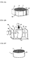
- Figs. 1A to 1C are each a drawing explaining a mode of the honeycomb structure.
- Fig. 1A is a perspective view of a honeycomb segment;
- Fig. 1B is a perspective view of a honeycomb structure;
- Fig. 1C is a plan view of a honeycomb structure.
- the honeycomb structure 1 of the present mode is produced by bonding, with a bonding material, a plurality of honeycomb segments 12 each comprising a cell structure 5 having a plurality of cells 3 divided by porous partition walls 2 and functioning as a fluid passage, and a porous outer wall 7 provided at the periphery of the cell structure 5, to each other at the outer walls 7 of the honeycomb segments 12 to obtain an integral body.
- the first structure of the present mode is a honeycomb structure obtained by bonding with a bonding material containing a heat-gelling organic binder having a thickening-initiating temperature of 75°C or lower.
- the second is a honeycomb structure obtained by bonding with a bonding material containing a thermosetting resin.
- Organic binder refers generally to an organic bonding material, and bonding material refers to a material which is used for bonding or fixing solids of same kind or different kinds to form a part, a product, etc.
- the organic binder means organic compounds which are added to enable molding of ceramic raw material powder and impart the strength necessary for maintenance of the shape of the molding obtained.
- the organic binder is methyl cellulose.
- Gelling refers generally to a phenomenon in which a sol is changes to a gel. It occurs when a sol is cooled, or when a solvent, a salt or the like is added to a sol, or when a mechanical impact is applied to a sol. For example, when an aqueous gelatin solution is cooled, there occurs a transition from sol to gel; and the gel returns to a sol when heated. As such an example, agarose (a main component of agar) is also known.
- an organic binder which shows a so-called heat-gelling phenomenon in which, contrary to the above gelling, an aqueous solution thereof becomes a gel when heated and, when cooled, the gel returns to the original aqueous solution.
- Heat-gelling refers generally to a phenomenon in which an aqueous alkyl cellulose or hydroxyalkyl cellulose solution becomes a gel when heated and, when cooled, the gel returns to the original aqueous solution.
- Such an aqueous solution showing heat-gelling which is reversible phenomenon, which solution has different viscosity restore temperatures when heating and cooling, that is, a hysteresis property.
- substances showing heat-gelling there can be generally mentioned hydroxyethyl methyl cellulose, hydroxyethyl ethyl cellulose, hydroxypropyl methyl cellulose, hydroxypropyl ethyl cellulose, hydroxybutyl methyl cellulose, etc.
- methyl cellulose is used as the organic binder.
- the organic binder there is used only an organic binder which gels upon heating and whose gelling temperature is 75°C or lower.
- the organic binder is methyl cellulose.
- Thickening agent refers generally to a material which is added to increase the viscosity of a fluid.
- Cellulose derivatives such as methyl cellulose, carboxymethyl cellulose and the like are a thickening agent dispersible in water.
- the thickening action of the organic binder suppresses the fluidity of the bonding material.
- methyl cellulose becomes a gel when heated and, when cooled, becomes a sol. It is considered that the crosslinking zone brought about by gelling is formed by a hydrophobic interaction.
- methyl cellulose products of different properties are being marketed by Sin-Etsu Chemical Co., Ltd. under the trade name of "Metolose”.
- the bonding material used in the present invention contains any of inorganic particles and a colloidal oxide.
- the inorganic particles there can be mentioned powders of ceramics such as cordierite, silicon carbide, silicon nitride, alumina, mullite, zirconia, zirconium phosphate, aluminum titanate, titania and the like; and powders obtained by combining two or more kinds of the above powders.
- the bonding material can have an improved affinity by being appropriately selected in view of the matching with the material of honeycomb segment (kind of ceramic) on which the bonding material is to be coated.
- a cordierite powder or a silicon carbide powder can be used preferably.
- colloidal oxide there can be mentioned, for example, silica sol, alumina sol, colloidal silica and colloidal alumina. They may be used singly or in combination of two or more kinds.
- the cell density of honeycomb segment (the number of cells per unit honeycomb sectional area intersecting the fluid passages of honeycomb segment at right angles), there is no particular restriction.
- too small a cell density results in an insufficient geometric surface area and a too large a cell density results in too large a pressure loss; therefore, none of them is preferred.
- the cell density is preferably 0.9 to 310 cells/cm 2 (6 to 2,000 cells/in 2 ).
- shape of cell section (cell section intersecting the fluid passage at right angles), there is no particular restriction, either.
- the cell sectional shape may be any selected from polygons such as triangle, tetragon and hexagon, circle, oval, corrugation, etc.; however, it is preferably a triangle, a tetragon or a hexagon from the standpoint of production.
- the thickness of partition wall there is no particular restriction, either. However, too small a partition wall thickness results in an insufficient strength of honeycomb segment and too large a thickness results in too large a pressure loss; therefore, none of them is preferred.
- the thickness of partition wall is preferably 50 to 2,000 ⁇ m.
- honeycomb segment there is no particular restriction, either, and any shape can be employed.
- a square pole shape such as shown in Fig. 1A is used as a basic shape, such basic shapes are bonded into one piece as shown in Fig. 1B , and the honeycomb segments 12 constituting the outer surface of honeycomb structure 1 are allowed to have shapes matching the peripheral shape of honeycomb structure 1.
- the section of each honeycomb segment intersecting the fluid passages of honeycomb segment at right angles has a fan shape.
- any shape can be selected from round shape such as true circle, oval, ellipse, or polygon such as triangle, tetragon or pentagon, amorphous shape, etc.
- a metal having a catalytic activity may be preferably loaded on the honeycomb structure.
- Representative metals having a catalytic activity include platinum (Pt), palladium (Pd), rhodium (Rd), etc. At least one kind of these is preferably loaded on the honeycomb structure.
- the honeycomb structure when used as a filter (e.g. DPF) for capture/removal of particulate substance (soot) present in exhaust gas, it is preferred that a given number of cells are plugged at one end face of the honeycomb structure, the remainder of cells are plugged at other end face, and neighboring cells, when seen at each end face, are plugged alternately (each end face looks checkerwise and each cell is plugged at either of the two ends).
- a soot-containing exhaust gas incoming from one end face of honeycomb structure passes through the partition walls and leaves from other end face of honeycomb structure.
- the porous partition walls function as a filter and can capture the soot.
- the captured soot accumulates on the partition walls, an increase in pressure loss appears; as a result, engine undergoes a load and there appears a reduction in fuel consumption and operability; therefore, it becomes necessary to periodically burn and remove the soot using a heating means such as heater and regenerate the function of the filter.
- a heating means such as heater and regenerate the function of the filter.
- the above-mentioned metal having a catalytic activity may be loaded on the honeycomb structure.
- the honeycomb structure obtained by bonding is subjected to hot-air drying or the like, to vaporize the water contained in the bonding material and allow the honeycomb structure to express a strength necessary for shape maintenance.
- the temperature in the vicinity of the bonding material shows no increase and remains stagnant at 75 to 100°C owing to the heat of vaporization of water.
- each bonded portion has strong areas and weak areas, which gives rise to the non-uniformity of shrinkage and the shifting of bonded portion, caused by vibration or self-weight.
- a heat-gelling organic binder having a thickening-initiating temperature of 75°C or lower a strength is imparted to each bonded portion prior to the stagnation of temperature rise.
- the effect of heat-gelling is larger as the addition amount of organic binder is larger and, when the addition amount is smaller than 0.1 mass %, the effect does not spread to all the particles of bonding material and no sufficient effect is expected.
- the effect is expectable when bonding is made with a bonding material containing the organic binder preferably in an amount of 1 mass % or more, and the effect is particularly striking when the content of organic binder is 5 mass % or more.
- the effect is further striking when the organic binder has a thickening-initiating temperature of 75°C or lower.
- the organic binder is methyl cellulose.
- thermosetting resin can show an effect as an accelerator for drying and curing, too.
- the thermosetting resin refers generally to a compound (e.g. a natural or synthetic resin) which can show the insolubility or non-fusibility exhibited by liquid or plastic substance when catalyzed, heated or given an energy (e.g. light).
- the thermosetting resin described herein when heated, gives rise to a crosslinking reaction between the molecules and is converted to a non-fusible, insoluble polymer having a three-dimensional network structure.
- urea resin, melamine resin, phenolic resin, epoxy resin, unsaturated polyester resin and acrylic resin can be mentioned, for example, urea resin, melamine resin, phenolic resin, epoxy resin, unsaturated polyester resin and acrylic resin.
- thermosetting resin can be used as an accelerator for drying and curing, and a phenolic resin, an epoxy resin, etc. are particularly preferred.
- thermosetting resin In using a bonding material containing a heat-gelling organic binder or a thermosetting resin, it is effective, for arrival at a thickening-initiating temperature or a thermosetting temperature in a short time, to conduct drying by applying a micro wave, or to conduct drying by dielectric heating, or to conduct drying by heating a honeycomb structure not only from outside but also from inside.
- the temperature elevation time up to thickening-initiating temperature or thermosetting temperature can be shortened by using heated honeycomb segments. It is also effective to conduct bonding using a bonding material and immediately subjecting the resulting body to an atmosphere of 100°C.
- drying of bonding material refers to that the liquid component in the bonding material is vaporized at a temperature at which the components in the bonding material causes no fusion or the like, that is, causes substantially no firing and, as a result, the bonding material is solidified (gelled).
- the honeycomb structure presently described is obtained by drying alone (no firing takes place) of bonding material, resultant formation of bonding layer, and subsequent bonding of honeycomb segments to each other at their outer walls; therefore, in the honeycomb structure, there hardly appear bonding defects such as cracking in bonding layer, peeling of bonding layer per se and the like, caused, for example, by differences in thermal expansion coefficient and shrinkage ratio between bonding layer and honeycomb segment.
- the bonding layer is formed by drying alone (no firing takes place) of bonding material and, thereby, honeycomb segments are bonded to each other at the outer walls; therefore, the effect that bonding defects hardly appear, is striking particularly when the honeycomb structure is large.
- At least part of the periphery of the honeycomb structure (bonded body) obtained by bonding of honeycomb segments may be removed as necessary.
- cells 3 are removed from the outer wall preferably by at least two cells, more preferably by two to four cells.
- removal of cells means that at least part of the partition walls forming each cell is removed and the four sides of the bonded body are made not to be completely surrounded by partition walls.
- the removal can be conducted, for example, by grinding a bonded body 36 from its periphery using a grinding means such as diamond tool 42 or the like, to remove removal portions 41 including a plurality of cells 3.
- a coating material 43 is coated on the removed portions to form an outer wall 50 of a honeycomb structure 1 as shown in Fig. 2B and Fig. 2C .
- the coating material 43 preferably contains at least one member selected from colloidal silica, colloidal alumina, ceramic fiber and ceramic particles.
- the ceramic particles include, for example, silicon carbide.
- a periphery-coating machine 48 such as shown in Fig. 2B is used, whereby an outer wall having a uniform thickness can be formed.
- the two end faces of the bonded body 36 in which part of the periphery has been removed are masked by an abutting jig 47 composed of nylon, polyvinyl chloride or the like, and the bonded body 36 is held and fixed by a shaft 45 fitted with a rotary handle 46 at one end. Then, the handle 46 is rotated and a coating material 43 can be uniformly coated on the periphery of the bonded body 36 with a leveling plate 44.
- the thickness of the outer wall can be set by appropriately adjusting the size of the abutting member 47 relative to the size of the bonded body 36.
- the bonding material used in the present invention forms a bonding layer by simply being dried without being fired and thereby can bond to-be-bonded bodies to each other; therefore, an effect that bonding defects hardly appear, appears strikingly particularly when each to-be-bonded body is large (the coating area by bonding material is large).
- the bonding material described herein is preferably used in mutual bonding of bonding surfaces (outer walls) of a plurality of porous honeycomb segments composed of ceramic.
- the ceramic constituting each porous honeycomb segment there can be mentioned, for example, cordierite, silicon carbide, silicon nitride, alumina, mullite, zirconia, zirconium phosphate, aluminum titanate, silicon carbide-silicon composite material, and titania.
- a silicon carbide powder and a silicon powder were mixed as raw materials for honeycomb segment, at a mass ratio of 80:20. Thereto were added, as pore formers, starch and a foamed resin. There were further added methyl cellulose, hydroxypropoxyl methyl cellulose, a surfactant and water to prepare plastic clay. The clay was subjected to extrusion and the extrudate was dried by a micro wave and hot air to obtain a honeycomb segment formed body having a partition wall thickness of 310 ⁇ m, a cell density of 46.5 cells/cm 2 (300 cells/in 2 ), a square sectional shape of 35 mm x 35 mm, and a length of 152 mm.
- the cell ends of the honeycomb segment formed body were plugged so that the two end faces of the formed body looked checkerwise. That is, the plugging was conducted so that each cell is plugged at one end and each two neighboring cells are plugged at different ends.
- the plugging agent the same materials as the raw materials for honeycomb segment were used. After the plugging of cell ends, drying was conducted; then, degreasing was conducted in the atmosphere at about 400°C; thereafter, firing was conducted in an Ar inert atmosphere at about 1,450°C to obtain a honeycomb segment of porous structure in which SiC crystal particles were bonded by Si.
- each of the bonding materials shown in Table 1 16 same honeycomb segments were bonded with a target bonding width of 1 mm; drying was conducted at 200°C for 2 hours; then, dispersion of bonding width and shifting of bonding were observed. The dispersion of bonding width was measured at various bonding sites (24 sites). The shifting of bonding was confirmed by counting the number of sites where the shifting by two cells or more was observed. Further, the periphery of each bonded body obtained was ground so that the bonded body after grinding had a cylindrical shape; a coating material was coated on the ground surface; and a heat treatment was applied at 500°C for 2 hours to obtain each honeycomb structure.
- honeycomb structures of the present invention each obtained by bonding with a bonding material containing 0.2 to 6 mass % of a heat-gelling organic binder having a thickening-initiating temperature of 75°C or lower, showed neither shifting of bonding nor after-test cracking.
- honeycomb structure process for production thereof and bonding material, according to the present invention, there can be suppressed the dispersion of bonding width and shifting of bonding, which have hitherto arisen in bonding materials having fluidity before drying; therefore, they can be suitably used, for example, in a carrier for catalyst loading, installed in internal combustion engine, boiler, chemical reactor, fuel cell reformer, etc., or in a filter for capture of particulates in exhaust gas.
Landscapes
- Chemical & Material Sciences (AREA)
- Engineering & Computer Science (AREA)
- Ceramic Engineering (AREA)
- Structural Engineering (AREA)
- Organic Chemistry (AREA)
- Materials Engineering (AREA)
- Chemical Kinetics & Catalysis (AREA)
- Manufacturing & Machinery (AREA)
- Inorganic Chemistry (AREA)
- Health & Medical Sciences (AREA)
- Toxicology (AREA)
- Combustion & Propulsion (AREA)
- Mechanical Engineering (AREA)
- General Engineering & Computer Science (AREA)
- Filtering Materials (AREA)
- Ceramic Products (AREA)
- Catalysts (AREA)
Claims (1)
- Verfahren zur Herstellung einer aus Keramik hergestellten Wabenstruktur (1), das einen Verbindungsschritt eines haftschlüssigen Verbindens einer Vielzahl von Wabensegmenten (12) mit einem Haftverbindungsmaterial, die jeweils eine Zellstruktur (5) mit einer Vielzahl von Zellen (3), die durch poröse Trennwände (2) unterteilt sind und als ein Fluiddurchlass fungieren, und eine poröse Außenwand (7), die am Randbereich der Zellstruktur (5) bereitgestellt ist, umfassen, miteinander an den Außenwänden (7) der Wabensegmente (12) umfasst, um einen einstückig ausgebildeten Körper zu erhalten, wobei in dem Verbindungsschritt ein Haftverbindungsmaterial, das 0,1 Masse-% oder mehr eines wärmegelierenden organischen Bindemittels enthält, das eine Verdickungsinitierungstemperatur von 75 °C oder weniger aufweist, auf jeder Außenwand (7) aufgetragen wird, das aufgetragene Haftverbindungsmaterial bei einer Temperatur von 100 °C oder mehr, bei der kein Brennen erfolgt, getrocknet wird, eine Flüssigkeitskomponente des Haftverbindungsmaterials verdampft und das Haftverbindungsmaterial sich verfestigt, um eine Haftverbindungsschicht (8) zu bilden, und die Außenwände (7) über die Haftverbindungsschicht (8) miteinander haftschlüssig verbunden werden;
wobei das organische Bindemittel Methylcellulose ist.
Applications Claiming Priority (2)
| Application Number | Priority Date | Filing Date | Title |
|---|---|---|---|
| JP2006081796 | 2006-03-23 | ||
| PCT/JP2007/056108 WO2007111281A1 (ja) | 2006-03-23 | 2007-03-23 | ハニカム構造体及びその製造方法、並びに接合材 |
Publications (3)
| Publication Number | Publication Date |
|---|---|
| EP2006266A1 EP2006266A1 (de) | 2008-12-24 |
| EP2006266A4 EP2006266A4 (de) | 2010-08-11 |
| EP2006266B1 true EP2006266B1 (de) | 2019-10-09 |
Family
ID=38541198
Family Applications (1)
| Application Number | Title | Priority Date | Filing Date |
|---|---|---|---|
| EP07739549.9A Ceased EP2006266B1 (de) | 2006-03-23 | 2007-03-23 | Herstellungsverfahren einer wabenstruktur |
Country Status (5)
| Country | Link |
|---|---|
| US (1) | US20090035512A1 (de) |
| EP (1) | EP2006266B1 (de) |
| JP (1) | JPWO2007111281A1 (de) |
| KR (1) | KR20090010170A (de) |
| WO (1) | WO2007111281A1 (de) |
Families Citing this family (9)
| Publication number | Priority date | Publication date | Assignee | Title |
|---|---|---|---|---|
| FR2902423B1 (fr) | 2006-06-19 | 2008-09-12 | Saint Gobain Ct Recherches | Ciment de jointoiement pour filtre a particules. |
| FR2902424B1 (fr) | 2006-06-19 | 2008-10-17 | Saint Gobain Ct Recherches | Ciment de jointoiement a spheres creuses pour filtre a particules. |
| US8613273B2 (en) * | 2011-06-08 | 2013-12-24 | Royce Walker & Co., Ltd | Fuel conditioning modules and methods |
| DE112013002164T5 (de) * | 2012-04-23 | 2015-01-29 | Dow Global Technologies Llc | Axial geschnittene keramische Wabeneinheiten |
| ITMI20122251A1 (it) * | 2012-12-28 | 2014-06-29 | Eni Spa | Reattore pluristrutturato per processi chimici con elevato scambio termico |
| JP6285234B2 (ja) * | 2014-03-25 | 2018-02-28 | 日本碍子株式会社 | ハニカム構造体の製造方法 |
| WO2018005350A1 (en) * | 2016-06-28 | 2018-01-04 | Dow Global Technologies Llc | Method for additive manufacturing porous inorganic structures and composites made therefrom |
| WO2019108918A1 (en) * | 2017-11-30 | 2019-06-06 | Corning Incorporated | Ceramic articles with bleed-through barrier and methods of manufacture thereof |
| EP3887019B1 (de) * | 2018-11-30 | 2022-12-21 | Corning Incorporated | Verfahren zur herstellung von zusammensteckbaren wabenkörpern mit zementplättchen |
Family Cites Families (11)
| Publication number | Priority date | Publication date | Assignee | Title |
|---|---|---|---|---|
| JPH0645500B2 (ja) * | 1989-07-03 | 1994-06-15 | 松下電器産業株式会社 | ハニカム状セラミックスの製造方法 |
| JP3227039B2 (ja) * | 1993-11-16 | 2001-11-12 | 日本碍子株式会社 | コージェライトハニカム構造体の製造方法 |
| JP3971027B2 (ja) | 1998-06-25 | 2007-09-05 | イビデン株式会社 | セラミックス構造体の接合装置及び接合方法 |
| US7309370B2 (en) * | 2002-02-05 | 2007-12-18 | Ibiden Co., Ltd. | Honeycomb filter for exhaust gas decontamination |
| EP1719881B1 (de) | 2002-02-05 | 2016-12-07 | Ibiden Co., Ltd. | Wabenfilter zur Abgasreinigung, Klebstoff, Beschichtungsmaterial und Verfahren zur Herstellung eines Wabenfilters zur Abgasreinigung |
| JP4382367B2 (ja) * | 2003-01-14 | 2009-12-09 | 日本碍子株式会社 | セラミックハニカム構造体の接合方法 |
| JP4331575B2 (ja) * | 2003-11-26 | 2009-09-16 | 日本碍子株式会社 | ハニカム構造体及びその製造方法、並びに接合材 |
| US7387829B2 (en) * | 2004-01-13 | 2008-06-17 | Ibiden Co., Ltd. | Honeycomb structure, porous body, pore forming material for the porous body, and methods for manufacturing the pore forming material, the porous body and the honeycomb structure |
| KR100796471B1 (ko) * | 2004-04-30 | 2008-01-21 | 니뽄 가이시 가부시키가이샤 | 허니컴 구조체 및 그 제조 방법 |
| JP2006062944A (ja) * | 2004-07-28 | 2006-03-09 | Kyocera Corp | セラミック焼結体の製造方法とこれにより得られた光通信用フェルール |
| US20060272306A1 (en) * | 2005-06-01 | 2006-12-07 | Kirk Brian S | Ceramic wall flow filter manufacture |
-
2007
- 2007-03-23 KR KR1020087025837A patent/KR20090010170A/ko not_active Ceased
- 2007-03-23 WO PCT/JP2007/056108 patent/WO2007111281A1/ja not_active Ceased
- 2007-03-23 JP JP2008507481A patent/JPWO2007111281A1/ja active Pending
- 2007-03-23 EP EP07739549.9A patent/EP2006266B1/de not_active Ceased
-
2008
- 2008-09-18 US US12/233,225 patent/US20090035512A1/en not_active Abandoned
Non-Patent Citations (1)
| Title |
|---|
| None * |
Also Published As
| Publication number | Publication date |
|---|---|
| WO2007111281A1 (ja) | 2007-10-04 |
| EP2006266A4 (de) | 2010-08-11 |
| JPWO2007111281A1 (ja) | 2009-08-13 |
| EP2006266A1 (de) | 2008-12-24 |
| US20090035512A1 (en) | 2009-02-05 |
| KR20090010170A (ko) | 2009-01-29 |
Similar Documents
| Publication | Publication Date | Title |
|---|---|---|
| EP1550494B1 (de) | Wabenstruktur | |
| US20090035512A1 (en) | Honeycomb structure, process for producing the same, and bonding material | |
| EP1452511B1 (de) | Verfahren zur herstellung eines wabenkörpers | |
| EP1741686B1 (de) | Wabenstruktur und herstellungsverfahren dafür | |
| EP2292902B1 (de) | Herstellungsverfahren für einen Wabenstrukturkörper | |
| EP1486243B1 (de) | Wabenfilter | |
| EP1780385B1 (de) | Wabenstruktur | |
| EP2119487B1 (de) | Wabenstruktur und herstellungsverfahren dafür | |
| US8039086B2 (en) | Bonding material, process for producing the same, and honeycomb structure made with the same | |
| EP2179977B1 (de) | Beschichtungsmaterial für eine wabenstruktur | |
| EP2174921B1 (de) | Klebematerial für eine wabenstruktur und dieses verwendende wabenstruktur | |
| EP2177253B1 (de) | Wabenstruktur | |
| EP2006264B1 (de) | Wabenstruktur und herstellungsverfahren dafür | |
| EP1375853B1 (de) | Wabenkonstruktion und deren zusammenbau | |
| EP2008987B1 (de) | Wabenstrukturkörper | |
| EP1600433B1 (de) | Wabenstruktur | |
| EP1860082B1 (de) | Wabenstruktur | |
| KR100762196B1 (ko) | 허니컴 구조체 | |
| US20090291828A1 (en) | Honeycomb structure | |
| EP2127720B1 (de) | Wabenstruktur |
Legal Events
| Date | Code | Title | Description |
|---|---|---|---|
| PUAI | Public reference made under article 153(3) epc to a published international application that has entered the european phase |
Free format text: ORIGINAL CODE: 0009012 |
|
| 17P | Request for examination filed |
Effective date: 20081007 |
|
| AK | Designated contracting states |
Kind code of ref document: A1 Designated state(s): DE FR PL |
|
| RBV | Designated contracting states (corrected) |
Designated state(s): DE FR PL |
|
| A4 | Supplementary search report drawn up and despatched |
Effective date: 20100713 |
|
| 17Q | First examination report despatched |
Effective date: 20120210 |
|
| DAX | Request for extension of the european patent (deleted) | ||
| GRAP | Despatch of communication of intention to grant a patent |
Free format text: ORIGINAL CODE: EPIDOSNIGR1 |
|
| INTG | Intention to grant announced |
Effective date: 20190425 |
|
| GRAS | Grant fee paid |
Free format text: ORIGINAL CODE: EPIDOSNIGR3 |
|
| GRAA | (expected) grant |
Free format text: ORIGINAL CODE: 0009210 |
|
| AK | Designated contracting states |
Kind code of ref document: B1 Designated state(s): DE FR PL |
|
| RIN1 | Information on inventor provided before grant (corrected) |
Inventor name: ICHIKAWA, SHUICHI Inventor name: WATANABE, ATSUSHI Inventor name: MASUKAWA, NAOSHI |
|
| REG | Reference to a national code |
Ref country code: DE Ref legal event code: R096 Ref document number: 602007059329 Country of ref document: DE |
|
| PG25 | Lapsed in a contracting state [announced via postgrant information from national office to epo] |
Ref country code: PL Free format text: LAPSE BECAUSE OF FAILURE TO SUBMIT A TRANSLATION OF THE DESCRIPTION OR TO PAY THE FEE WITHIN THE PRESCRIBED TIME-LIMIT Effective date: 20191009 |
|
| REG | Reference to a national code |
Ref country code: DE Ref legal event code: R097 Ref document number: 602007059329 Country of ref document: DE |
|
| PLBE | No opposition filed within time limit |
Free format text: ORIGINAL CODE: 0009261 |
|
| STAA | Information on the status of an ep patent application or granted ep patent |
Free format text: STATUS: NO OPPOSITION FILED WITHIN TIME LIMIT |
|
| 26N | No opposition filed |
Effective date: 20200710 |
|
| PG25 | Lapsed in a contracting state [announced via postgrant information from national office to epo] |
Ref country code: FR Free format text: LAPSE BECAUSE OF NON-PAYMENT OF DUE FEES Effective date: 20200331 |
|
| PGFP | Annual fee paid to national office [announced via postgrant information from national office to epo] |
Ref country code: DE Payment date: 20210310 Year of fee payment: 15 |
|
| REG | Reference to a national code |
Ref country code: DE Ref legal event code: R119 Ref document number: 602007059329 Country of ref document: DE |
|
| PG25 | Lapsed in a contracting state [announced via postgrant information from national office to epo] |
Ref country code: DE Free format text: LAPSE BECAUSE OF NON-PAYMENT OF DUE FEES Effective date: 20221001 |