EP2006267A1 - Procede et element de jonction de ceramique - Google Patents
Procede et element de jonction de ceramique Download PDFInfo
- Publication number
- EP2006267A1 EP2006267A1 EP07739852A EP07739852A EP2006267A1 EP 2006267 A1 EP2006267 A1 EP 2006267A1 EP 07739852 A EP07739852 A EP 07739852A EP 07739852 A EP07739852 A EP 07739852A EP 2006267 A1 EP2006267 A1 EP 2006267A1
- Authority
- EP
- European Patent Office
- Prior art keywords
- joined
- ceramic
- heating
- joining
- ceramics
- Prior art date
- Legal status (The legal status is an assumption and is not a legal conclusion. Google has not performed a legal analysis and makes no representation as to the accuracy of the status listed.)
- Withdrawn
Links
Images


Classifications
-
- C—CHEMISTRY; METALLURGY
- C04—CEMENTS; CONCRETE; ARTIFICIAL STONE; CERAMICS; REFRACTORIES
- C04B—LIME, MAGNESIA; SLAG; CEMENTS; COMPOSITIONS THEREOF, e.g. MORTARS, CONCRETE OR LIKE BUILDING MATERIALS; ARTIFICIAL STONE; CERAMICS; REFRACTORIES; TREATMENT OF NATURAL STONE
- C04B37/00—Joining burned ceramic articles with other burned ceramic articles or other articles by heating
- C04B37/001—Joining burned ceramic articles with other burned ceramic articles or other articles by heating directly with other burned ceramic articles
-
- C—CHEMISTRY; METALLURGY
- C04—CEMENTS; CONCRETE; ARTIFICIAL STONE; CERAMICS; REFRACTORIES
- C04B—LIME, MAGNESIA; SLAG; CEMENTS; COMPOSITIONS THEREOF, e.g. MORTARS, CONCRETE OR LIKE BUILDING MATERIALS; ARTIFICIAL STONE; CERAMICS; REFRACTORIES; TREATMENT OF NATURAL STONE
- C04B37/00—Joining burned ceramic articles with other burned ceramic articles or other articles by heating
- C04B37/003—Joining burned ceramic articles with other burned ceramic articles or other articles by heating by means of an interlayer consisting of a combination of materials selected from glass, or ceramic material with metals, metal oxides or metal salts
-
- C—CHEMISTRY; METALLURGY
- C04—CEMENTS; CONCRETE; ARTIFICIAL STONE; CERAMICS; REFRACTORIES
- C04B—LIME, MAGNESIA; SLAG; CEMENTS; COMPOSITIONS THEREOF, e.g. MORTARS, CONCRETE OR LIKE BUILDING MATERIALS; ARTIFICIAL STONE; CERAMICS; REFRACTORIES; TREATMENT OF NATURAL STONE
- C04B37/00—Joining burned ceramic articles with other burned ceramic articles or other articles by heating
- C04B37/02—Joining burned ceramic articles with other burned ceramic articles or other articles by heating with metallic articles
-
- C—CHEMISTRY; METALLURGY
- C04—CEMENTS; CONCRETE; ARTIFICIAL STONE; CERAMICS; REFRACTORIES
- C04B—LIME, MAGNESIA; SLAG; CEMENTS; COMPOSITIONS THEREOF, e.g. MORTARS, CONCRETE OR LIKE BUILDING MATERIALS; ARTIFICIAL STONE; CERAMICS; REFRACTORIES; TREATMENT OF NATURAL STONE
- C04B2237/00—Aspects relating to ceramic laminates or to joining of ceramic articles with other articles by heating
- C04B2237/02—Aspects relating to interlayers, e.g. used to join ceramic articles with other articles by heating
- C04B2237/04—Ceramic interlayers
- C04B2237/08—Non-oxidic interlayers
-
- C—CHEMISTRY; METALLURGY
- C04—CEMENTS; CONCRETE; ARTIFICIAL STONE; CERAMICS; REFRACTORIES
- C04B—LIME, MAGNESIA; SLAG; CEMENTS; COMPOSITIONS THEREOF, e.g. MORTARS, CONCRETE OR LIKE BUILDING MATERIALS; ARTIFICIAL STONE; CERAMICS; REFRACTORIES; TREATMENT OF NATURAL STONE
- C04B2237/00—Aspects relating to ceramic laminates or to joining of ceramic articles with other articles by heating
- C04B2237/30—Composition of layers of ceramic laminates or of ceramic or metallic articles to be joined by heating, e.g. Si substrates
- C04B2237/32—Ceramic
- C04B2237/34—Oxidic
- C04B2237/343—Alumina or aluminates
-
- C—CHEMISTRY; METALLURGY
- C04—CEMENTS; CONCRETE; ARTIFICIAL STONE; CERAMICS; REFRACTORIES
- C04B—LIME, MAGNESIA; SLAG; CEMENTS; COMPOSITIONS THEREOF, e.g. MORTARS, CONCRETE OR LIKE BUILDING MATERIALS; ARTIFICIAL STONE; CERAMICS; REFRACTORIES; TREATMENT OF NATURAL STONE
- C04B2237/00—Aspects relating to ceramic laminates or to joining of ceramic articles with other articles by heating
- C04B2237/30—Composition of layers of ceramic laminates or of ceramic or metallic articles to be joined by heating, e.g. Si substrates
- C04B2237/32—Ceramic
- C04B2237/34—Oxidic
- C04B2237/345—Refractory metal oxides
- C04B2237/348—Zirconia, hafnia, zirconates or hafnates
-
- C—CHEMISTRY; METALLURGY
- C04—CEMENTS; CONCRETE; ARTIFICIAL STONE; CERAMICS; REFRACTORIES
- C04B—LIME, MAGNESIA; SLAG; CEMENTS; COMPOSITIONS THEREOF, e.g. MORTARS, CONCRETE OR LIKE BUILDING MATERIALS; ARTIFICIAL STONE; CERAMICS; REFRACTORIES; TREATMENT OF NATURAL STONE
- C04B2237/00—Aspects relating to ceramic laminates or to joining of ceramic articles with other articles by heating
- C04B2237/30—Composition of layers of ceramic laminates or of ceramic or metallic articles to be joined by heating, e.g. Si substrates
- C04B2237/32—Ceramic
- C04B2237/36—Non-oxidic
- C04B2237/365—Silicon carbide
-
- C—CHEMISTRY; METALLURGY
- C04—CEMENTS; CONCRETE; ARTIFICIAL STONE; CERAMICS; REFRACTORIES
- C04B—LIME, MAGNESIA; SLAG; CEMENTS; COMPOSITIONS THEREOF, e.g. MORTARS, CONCRETE OR LIKE BUILDING MATERIALS; ARTIFICIAL STONE; CERAMICS; REFRACTORIES; TREATMENT OF NATURAL STONE
- C04B2237/00—Aspects relating to ceramic laminates or to joining of ceramic articles with other articles by heating
- C04B2237/30—Composition of layers of ceramic laminates or of ceramic or metallic articles to be joined by heating, e.g. Si substrates
- C04B2237/32—Ceramic
- C04B2237/36—Non-oxidic
- C04B2237/366—Aluminium nitride
-
- C—CHEMISTRY; METALLURGY
- C04—CEMENTS; CONCRETE; ARTIFICIAL STONE; CERAMICS; REFRACTORIES
- C04B—LIME, MAGNESIA; SLAG; CEMENTS; COMPOSITIONS THEREOF, e.g. MORTARS, CONCRETE OR LIKE BUILDING MATERIALS; ARTIFICIAL STONE; CERAMICS; REFRACTORIES; TREATMENT OF NATURAL STONE
- C04B2237/00—Aspects relating to ceramic laminates or to joining of ceramic articles with other articles by heating
- C04B2237/30—Composition of layers of ceramic laminates or of ceramic or metallic articles to be joined by heating, e.g. Si substrates
- C04B2237/32—Ceramic
- C04B2237/36—Non-oxidic
- C04B2237/368—Silicon nitride
Definitions
- the present invention relates to methods of joining ceramics and ceramic joined articles. More specifically, the present invention relates to methods of joining ceramics and ceramic joined articles using an electromagnetic wave such as a microwave.
- the heating method may be laser irradiation, microwave irradiation or the like.
- the method has problems that only ceramics of oxides can be joined, that a heat crack is easily generated unfortunately, and that a residual of an air bubble in a joined part and a coarse of a crystal grain occur in some cases unfortunately.
- JP-2-62516-B (Patent document 1) describes a method of joining ceramics using a ceramic joining apparatus comprising a resonance cavity, a microwave generating means, a pressurization means for pressurizing surfaces to be joined of the ceramics put in the microwave resonance cavity, and a temperature control means for controlling a temperature distribution in the ceramics.
- JP-2-62516-B describes that since only each surface to be joined of the ceramics is heated uniformly and rapidly by using the method, the ceramics can be joined efficiently and tightly.
- Patent document 1 is effective for a joining of a material such as alumina, silicon carbide, and silicon nitride.
- a material such as alumina, silicon carbide, and silicon nitride.
- ceramic having an extremely small dielectric loss factor such as aluminum nitride cannot be joined by the method.
- the present invention has been made in consideration of such conditions, and an object of the present invention is to provide a joining method that enables to join efficiently and tightly even ceramics having an extremely small dielectric loss factor such as aluminum nitride together.
- a method of joining ceramics of the present invention is a method of thermally joining ceramics of the same kind or different kinds by inducing self-heating of the ceramics by electromagnetic wave irradiation, and comprises preheating a surface to be joined of the ceramic by a heating means that comprises an auxiliary heating means other than the self-heating.
- the preheating is preferably carried out up to a temperature in which the rate of temperature increase of the ceramic due to the self-heating is 1°C per minute or higher in the vicinity of the surface to be joined of the ceramic.
- the preheating is preferably carried out up to a temperature in which the dielectric loss factor ( ⁇ r tan ⁇ ) of the ceramic is 0.005 or higher under the condition that the measuring frequency is 2.45 GHz in the vicinity of the surface to be joined of the ceramic.
- auxiliary heating means is a heating element placed around the surface to be joined of the ceramic.
- the heating element is a dielectric body made of a substance having a dielectric loss factor at room temperature (25°C) larger than that of the ceramic and self-heating of the dielectric body is induced by absorption of the electromagnetic wave. It is preferable that the dielectric body is made of a substance having a dielectric loss factor ( ⁇ r tan ⁇ ) of 0.003 or higher at room temperature (25°C) and a dielectric loss factor ( ⁇ r tan ⁇ ) of 0.5 or higher at 800°C, under the condition that the measuring frequency is 2.45 GHz.
- the heating element may be a resistance heating element.
- the auxiliary heating means may be a heating furnace.
- the frequency of the electromagnetic wave is preferably in the range of 0.2 to 30 GHz.
- the method of joining ceramics of the present invention enables to join ceramics having the following properties, together:
- a method of joining aluminum nitride bodies of the present invention comprises:
- a ceramic joined article of the present invention is formed by joining by the method as defined above.
- the surface to be joined of the ceramic is preheated in advance. Consequently, even when ceramic having an extremely small dielectric loss factor such as aluminum nitride is used, self-heating of the surface to be joined and an area in the vicinity thereof of the ceramic is induced by electromagnetic wave irradiation, and thereby the ceramics are efficiently and tightly joined together.
- the method of joining ceramics of the present invention is a method of heating ceramics of the same kind or different kinds by inducing self-heating of the ceramics by electromagnetic wave irradiation and thereby joining the ceramics together, and comprises preheating a surface to be joined of the ceramic by a heating means that comprises an auxiliary heating means other than the self-heating.
- the ceramic to be joined by the method of joining ceramics of the present invention may be alumina, silicon carbide, silicon nitride, aluminum nitride (AlN), aluminum oxynitride, silicon oxynitride, zirconia or the like.
- the ceramic having an extremely small dielectric loss factor is a ceramic having a dielectric loss factor ( ⁇ r tan ⁇ ) in the range of 0.0001 to 0.002 at room temperature (25°C) and a dielectric loss factor ( ⁇ r tan ⁇ ) in the range of 0.003 to 0.3 at 800°C, under the condition that the measuring frequency is 2.45 GHz, in particular, a ceramic having a dielectric loss factor ( ⁇ r tan ⁇ ) in the range of 0.0005 to 0.002 at room temperature (25°C) and a dielectric loss factor ( ⁇ r tan ⁇ ) in the range of 0.003 to 0.1 at 800°C, under the condition that the measuring frequency is 2.45 GHz.
- the dielectric loss factor ( ⁇ r tan ⁇ ) can be obtained by multiplying the relative dielectric constant ( ⁇ r ) of the ceramic by a dielectric loss tangent (tan ⁇ ) measured by an LCD meter.
- the ceramic having an extremely small dielectric loss factor examples include aluminum nitride (AlN), silicon nitride, and single crystal alumina. Table 1 shows values of the dielectric loss factor of aluminum nitride (AlN).
- the ceramics to be joined by the method of joining ceramics of the present invention may be ceramics of the same kind or ceramics of different kinds.
- the dielectric loss factor ( ⁇ r tan ⁇ ) is each in the range of 0.0001 to 0.002 at room temperature (25°C) and in the range of 0.003 to 0.3 at 800°C, under the condition that the measuring frequency is 2.45 GHz, and the difference in thermal expansion coefficient between the ceramics is within 5 ⁇ 10 -6 [K -1 ], preferably within 3 ⁇ 10 -6 [K -1 ].
- Examples of a combination of the ceramics of the different kinds include aluminum nitride (AlN) and silicon nitride, aluminum nitride (AlN) and single crystal alumina, and silicon nitride and single crystal alumina.
- ceramics of the same kind such as AlN and AlN are joined together.
- a shape of the ceramic to be joined is not restricted in particular.
- the shape of the ceramic to be joined may be a prism, a circular cylinder, or a block.
- the surfaces to be joined of the ceramics are made flat by an abrasive finishing or the like and a gap is prevented from being generated when ceramics are abutted to each other.
- the shape of the surface to be joined of the ceramic may be a plan shape as shown in Fig. 1(a) , a V-shape as shown in Fig. 1(b) , and a step-shape as shown in Fig. 1(c) .
- a number of the ceramics to be joined is not restricted in particular. For instance, two ceramics may be joined as shown in Fig. 2 (a) , three ceramics may be joined as shown in Fig. 2(b) , and more ceramics may be joined.
- the method of joining ceramics of the present invention is a method of heating ceramics of the same kind or different kinds by inducing self-heating of the ceramics by electromagnetic wave irradiation and thereby joining the ceramics, and comprises preheating a surface to be joined of the ceramic by a heating means that comprises an auxiliary heating means other than the self-heating.
- the temperature of the surface to be joined of the ceramic to be joined is increased by preheating up to a temperature in which heating based on the self-heating by electromagnetic wave irradiation becomes easy, that is, up to a temperature in which the self-heating is easily induced by absorption of the electromagnetic wave. Consequently, even ceramic such as aluminum nitride is used, self-heating of the ceramic can be induced by electromagnetic wave irradiation, and the ceramic can be heated and joined based on the self-heating.
- the temperature in which the self-heating of the ceramic to be joined is induced easily means a temperature in which a rate of temperature increase of the ceramic by the self-heating is 1°C per minute or higher for instance, preferably 3°C per minute or higher.
- the upper limit of the rate of temperature increase is 50°C per minute for instance, preferably 30°C per minute.
- the temperature depends on the kind of the ceramic and the frequency of the electromagnetic wave. For instance, if the frequency of the electromagnetic wave is 2.45 GHz, the self-heating of ceramic is easily induced at a temperature in which a dielectric loss factor ( ⁇ r tan ⁇ ) is 0.005 or higher.
- the self-heating of aluminum nitride is easily induced at a temperature of 1000°C or higher for instance, preferably at a temperature of 1200°C or higher.
- the surface to be joined of the ceramic is heated by a heating means that comprises an auxiliary heating means other than the self-heating of the ceramics to be joined.
- auxiliary heating means include a heating element placed around the surface to be joined of the ceramic.
- a preheating step using the heating element as the auxiliary heating means as shown in Fig. 5 , a shaped body made of a substance having a dielectric loss factor at around room temperature larger than that of the ceramics is placed around surface to be joined of the ceramic, self-heating of the substance is induced by electromagnetic wave irradiation. The temperature of the ceramics at an area in the vicinity of the surface to be joined is increased by the heat.
- the heating element is a shaped body of a substance having a dielectric loss factor larger than that of the ceramic to be joined.
- the substance having a large dielectric loss factor is, for instance, a substance in which the dielectric loss factor ( ⁇ r tan ⁇ ) is in the range of 0.003 to 2 at room temperature (25°C) and is in the range of 0.5 to 5 at 800°C, under the condition that the measuring frequency is 2.45 GHz, preferably a substance in which the dielectric loss factor ( ⁇ r tan ⁇ ) is in the range of 0.003 to 1 at room temperature (25°C) and is in the range of 0.5 to 2.5 at 800°C, under the condition that the measuring frequency is 2.45 GHz.
- Examples of the substance having a large dielectric loss factor include silicon carbide (SiC), zirconia (ZrO 2 ), and steatite. Table 2 shows values of the dielectric loss factor of these substances.
- the electromagnetic wave to be used is preferably an electromagnetic wave having a frequency in the range of 0.2 to 30 GHz (a microwave or a millimeter wave). For instance, and an electromagnetic wave of 2.45 GHz may be used.
- electromagnetic wave irradiation is carried out while at least an area in the vicinity of the surface to be joined of the ceramic is housed in a container that does not leak the electromagnetic wave to the outside thereof.
- a cavity resonator may also be used.
- the preheating is carried out up to a temperature in which the self-heating of one of these ceramics is induced easily and, by the self-heating, the other ceramic is heated.
- the preheating is carried out while ceramics to be joined are arranged on the position where the main heating will be carried out after the preheating and are made come into contact with each other. In doing so, it is not necessary to change the arrangement of the ceramics for the main heating, and the step of joining ceramics is simplified.
- the preheating is carried out without bringing the ceramics to be joined into contact with each other and, immediately after the preheating, the ceramics to be joined are brought into contact with each other to carry out the main heating.
- the heating element as the auxiliary heating means may be a resistance heating element.
- the heating element generates heat by not electromagnetic wave irradiation (the self-heating due to the electromagnetic wave absorption) but applying an electric current thereto.
- auxiliary heating means include a heating furnace and the like.
- ceramics to be joined are heated up to at least a temperature in which the self-heating can be induced easily by a heating furnace such as an electric heating furnace, and the self-heating of the ceramics is induced by electromagnetic wave irradiation to the surfaces to be joined immediately after the heating, thereby enabling joining the ceramics together.
- the preheating may be carried out by only the auxiliary heating means, and may also be carried out by using the auxiliary heating means together with inducing self-heating of the ceramic to be joined.
- the auxiliary heating means is a heating element that generates heat by an electromagnetic wave absorption as described above
- the ceramic to be joined is a substance having an extremely small dielectric loss factor such as aluminum nitride
- self-heating of only the heating element is induced in practice at room temperature when the heating element and the ceramic to be joined are irradiated with an electromagnetic wave. Consequently, the preheating is carried out by only the auxiliary heating means.
- the ceramic to be joined is a substance having a large dielectric loss factor such as silicon carbide
- self-heating of both the heating element and the ceramic to be joined are induced by electromagnetic wave irradiation thereto. Consequently, the preheating is carried out by using the auxiliary heating means together with induced self-heating of the ceramic to be joined.
- the ceramic to be joined is a substance having an extremely small dielectric loss factor such as aluminum nitride, both the heating element and the ceramic to be joined are heated by self-heating thereof induced by electromagnetic wave irradiation thereto at a high temperature.
- the surface to be joined and an area in the vicinity thereof of the ceramic heated by the auxiliary heating means up to a temperature in which the self-heating is induced easily are further heated (hereafter this further heating is referred to as "main heating") by electromagnetic wave irradiation to the surface to be joined (that is, by self-heating due to an electromagnetic wave absorption) while surfaces to be joined of the ceramics to be joined are made come into contact with each other, to join the ceramics together.
- a temperature of only the surface to be joined and an area in the vicinity thereof is locally increased by the preheating as described above, and thereby a value of a dielectric loss factor is increased. Consequently, in the main heating, only the surface to be joined and an area in the vicinity thereof can be efficiently heated by electromagnetic wave irradiation up to a temperature in which the joining can be carried out.
- the main heating is carried out while a temperature of the surface to be joined of ceramic is maintained to the temperature in which the self-heating is induced easily.
- the heating element When the heating element is used as the auxiliary heating means during the preheating, the heating element (the auxiliary heating means) may be removed in the main heating (may be moved to a position where the heating element makes little or no impact on the main heating). Moreover, the heating element can be used together as a heating means in the main heating. It is preferable to carry out the main heating after removing the heating element because a component of the heating element does not come to be mixed in the ceramic to be joined, and a heating efficiency to the ceramic to be joined is increased.
- the surfaces to be joined of the ceramics are pressurized by pressing the ceramics to each other in order to join the ceramics more tightly.
- a publicly known pressurizing means as shown in Fig. 3 (i.e., Fig. 17 of Patent document 1) comprising a symmetric concentric chucks 21 for holding an end opposite to the surface 11 to be joined of the ceramic 1 to be joined, an air cylinder 22 that can pressurize the chucks, and a table for moving 23 that can move the chucks while the chucks are pressurized may be used.
- the surfaces to be joined of ceramics are made come into direct contact with each other as described above.
- ceramic powder or a paste containing the powder may be placed between the surfaces to be joined.
- the ceramic powder powder of a ceramic having the same composition as that of the ceramic to be joined is used in normal. To heat the surface to be joined more efficiently, powder of ceramic having a dielectric loss factor larger than that of the ceramic to be joined may be used. An average particle diameter of the powder may be in the range of 0.1 to 15 ⁇ m for instance.
- the ratio of the ceramic powder and the sintering aid is in the above range, a sintering temperature of the ceramic powder is sufficiently decreased, the sintering aid is sufficiently volatilized or is sufficiently diffused in a ceramic joined article, and thereby the sintering aid is prevented from remaining locally in the vicinity of the joining surface.
- the sintering aid may be, for instance, an oxide, a nitride, a chloride, a nitrate, a carbonate, and a fluoride of a rare earth metal or an alkali earth metal, preferably Y 2 O 3 , CaO, and Yb 2 O 3 .
- a particle diameter of the ceramic powder and the sintering aid is in the range of 0.1 to 3 ⁇ m.
- the particle diameter, in particular the particle diameter of the ceramic is in the range of 0.1 to 3 ⁇ m, a ratio of a volume of the ceramic in a volume of the entire paste is large, and thereby a density after sintering is enlarged.
- Carbon powder may be contained in the paste. Containing the carbon powder is preferable from the viewpoint that volatilizing of the sintering aid can be accelerated during heating described later.
- volatilizing of the sintering aid can be preferably accelerated during sintering.
- a particle size of the carbon powder is preferably in the range of 0.1 to 10 ⁇ m. In the case in which a particle size of the carbon powder is in the range of 0.1 to 10 ⁇ m, a distribution of carbon in the paste can be uniformed.
- a solvent contained in the paste may be ethyl cellulose or terpineol.
- the content of the solvent in the paste may be in the range of 10 to 50 % by mass at room temperature (25°C).
- an electromagnetic wave having a frequency in the range of 0.2 to 30 GHz (a microwave or a millimeter wave) is preferably used, and an electromagnetic wave of 2.45 GHz may be used for instance.
- electromagnetic wave irradiation is carried out while at least an area in the vicinity of the surface to be joined of the ceramic is housed in a container that does not leak the electromagnetic wave to the outside thereof.
- the joining method of the present invention it is required to heat by electromagnetic wave irradiation only at least the surface to be joined and an area in the vicinity thereof of the ceramics. Consequently, a large ceramic joined article can be formed using a compact electromagnetic wave irradiation apparatus (a microwave sintering furnace or the like).
- a publicly known apparatus such as an apparatus disclosed in Patent document 1 may be used.
- the ceramic joined article of the present invention is formed by joining ceramics together by the method of joining ceramics of the present invention.
- the strength of the ceramic joined article of the present invention is satisfactory.
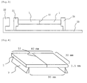
- the flexural strength in a three point flexural test at room temperature according to the flexural test method of fine ceramics at room temperature (JIS C2141) with a direct load applied to the joining part is 70% or higher and preferably 80% or higher of that of the base material, that is, the ceramic before joining. As shown in Fig.
- the value is a value measured according to the following procedure: setting a distance between supporting points to 30 mm, preparing a test piece having a length of 40 mm, a width of 30 mm, and a thickness of 1.5 mm, and provided with a joining part 12 (joining surface 11) at the center in a length direction, placing the test piece in such a manner that the joining part 12 is located at the center between the supporting points, and measuring the value with applying a load from the upper side of the joining part.
- a microwave sintering furnace (model number: MW-Master) (hereafter also referred to as a "jointing apparatus") manufactured by MINO CERAMIC CO., LTD. was used.
- the measurement of a temperature was carried out by using an infrared radiometer thermometer attached to the microwave sintering furnace.
- AlN aluminum nitride
- a three point flexural test was carried out according to the flexural test method of fine ceramics at room temperature (JIS C2141 specification). The distance between supporting points was set to 30 mm.
- the ceramic joined article was formed to be a sample material piece having a total length of 40 mm and a thickness of 1.5 mm, the test piece was placed in such a manner that the joining part is located at the center between the supporting points, and a load was applied to the joining part.
- Aluminum nitride sinters of 30 mm x 30 mm and a thickness of 2 mm were joined together as described in the following.
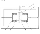
- two aluminum nitride (AlN) sinters 1 were placed in such a manner that the aluminum nitride (AlN) sinters 1 come into contact with each other at the center of the chassis of the joining apparatus 6.
- the surfaces to be joined (surfaces of 30 mm x 2 mm) of the aluminum nitride sinters 1 were flattened in order to prevent gap formation.
- the aluminum nitride sinters 1 were pressed to each other using a jig 3 to apply a pressure of 1 kgf/cm 2 (0.098 MPa) to the surfaces 11 to be joined.
- a pair of sinters 2 made of silicon carbide of 40 mm x 10 mm and a thickness of 2 mm was used as the preheating means. As shown in Fig. 5 , the pair of sinters 2 was placed around the surface to be joined of the aluminum nitride sinters 1 in such a manner that the pair of sinters 2 was apart from the aluminum nitride sinters 1 at a distance of 0.5 mm.
- the silicon carbide sinters 2 were irradiated with an electromagnetic wave (frequency: 2.45 GHz) from a microwave transmitter 5 to carry out the preheating.
- the preheating and the main heating were carried out in an atmosphere of nitrogen, and the preheating was started at room temperature.
- the output of the microwave was increased to 3000 W at a constant rate in 120 minutes.
- the self-heating of the silicon carbide sinters 2 was induced by electromagnetic wave irradiation, and a temperature of the surfaces 11 to be joined of the aluminum nitride sinters 1 were increased by this heat.
- the surface temperature of the preheating heating element (silicon carbide sinter 2) becomes 1300°C 60 minutes after the start of electromagnetic wave irradiation. Consequently, it was judged that the self-heating of the two aluminum nitride sinters 1 facing to each other had been induced at an area in the vicinity of the surfaces to be joined.
- the preheating heating element silicon carbide sinter 2
- silicon carbide sinter 2 was removed while electromagnetic wave irradiation was continued.
- the surface 11 to be joined of the aluminum nitride sinters 1 was further heated for 60 minutes to complete the joining of the two aluminum nitride sinters 1.
- the temperature of the joining part was 1700°C when the joining was completed.
- the electromagnetic wave irradiation was terminated and, then, the aluminum nitride joined article obtained was allowed to cool in the joining apparatus for 60 minutes and was taken out from the apparatus.
- a three point flexural test of the joined aluminum nitride sinters (aluminum nitride joined article) was carried out.
- the strength of the joined aluminum nitride sinters was the same as that of the aluminum nitride sinter before the joining.
Landscapes
- Chemical & Material Sciences (AREA)
- Engineering & Computer Science (AREA)
- Ceramic Engineering (AREA)
- Materials Engineering (AREA)
- Structural Engineering (AREA)
- Organic Chemistry (AREA)
- Ceramic Products (AREA)
Applications Claiming Priority (2)
| Application Number | Priority Date | Filing Date | Title |
|---|---|---|---|
| JP2006092289A JP2007261916A (ja) | 2006-03-29 | 2006-03-29 | セラミックスの接合方法およびセラミックス接合体 |
| PCT/JP2007/056414 WO2007116742A1 (fr) | 2006-03-29 | 2007-03-27 | Procede et element de jonction de ceramique |
Publications (2)
| Publication Number | Publication Date |
|---|---|
| EP2006267A1 true EP2006267A1 (fr) | 2008-12-24 |
| EP2006267A4 EP2006267A4 (fr) | 2009-09-02 |
Family
ID=38581040
Family Applications (1)
| Application Number | Title | Priority Date | Filing Date |
|---|---|---|---|
| EP07739852A Withdrawn EP2006267A4 (fr) | 2006-03-29 | 2007-03-27 | Procede et element de jonction de ceramique |
Country Status (6)
| Country | Link |
|---|---|
| US (1) | US20090173437A1 (fr) |
| EP (1) | EP2006267A4 (fr) |
| JP (1) | JP2007261916A (fr) |
| KR (1) | KR20080105117A (fr) |
| CN (1) | CN101415657A (fr) |
| WO (1) | WO2007116742A1 (fr) |
Families Citing this family (5)
| Publication number | Priority date | Publication date | Assignee | Title |
|---|---|---|---|---|
| US7988804B2 (en) * | 2008-05-02 | 2011-08-02 | Corning Incorporated | Material and method for bonding zircon blocks |
| JP5565772B2 (ja) * | 2009-06-29 | 2014-08-06 | 独立行政法人産業技術総合研究所 | 電磁波照射を用いた材料の接合方法及び接合装置 |
| JP5466439B2 (ja) * | 2009-06-30 | 2014-04-09 | 太平洋セメント株式会社 | セラミックス接合体並びにセラミックスヒータ、静電チャック及びサセプタ |
| CN105422946B (zh) * | 2015-12-20 | 2017-11-03 | 重庆市万通仪器仪表有限公司 | 陶瓷阀壳体 |
| JP7128393B2 (ja) * | 2020-09-16 | 2022-08-31 | 株式会社プラウド | 半導体結晶体の加工方法および半導体結晶体の加工装置 |
Family Cites Families (10)
| Publication number | Priority date | Publication date | Assignee | Title |
|---|---|---|---|---|
| JPS6311580A (ja) * | 1986-06-30 | 1988-01-19 | 株式会社豊田中央研究所 | セラミツクスの接合装置 |
| CA1313230C (fr) * | 1988-10-06 | 1993-01-26 | Raymond Roy | Procede de chauffage de materiaux par hyperfrequences |
| CA2001062A1 (fr) * | 1989-10-19 | 1991-04-19 | Prasad Shrikrishna Apte | Methode de traitement thermique aux micro-ondes de ceramiques instables; les materiaux interactifs ainsi utilises |
| CA2124093C (fr) * | 1994-03-31 | 2001-04-17 | Prasad S. Apte | Procede de frittage aux micro-ondes |
| US5847355A (en) * | 1996-01-05 | 1998-12-08 | California Institute Of Technology | Plasma-assisted microwave processing of materials |
| JPH09301783A (ja) * | 1996-05-14 | 1997-11-25 | Maruwa Ceramic:Kk | 金属とセラミックスの直接接合方法 |
| JPH10233294A (ja) * | 1997-02-17 | 1998-09-02 | Tokyo Electron Ltd | プラズマ処理装置 |
| JP2005506260A (ja) * | 2000-12-29 | 2005-03-03 | コーニング インコーポレイテッド | 電磁エネルギーを用いるセラミック処理方法 |
| DE112004001032T5 (de) * | 2003-06-13 | 2006-05-18 | Han, Joo-Hwan, Kyungsan | Verfahren zum Verbinden von Keramik: Reaktions-Diffusionsbinden |
| JP2005154169A (ja) * | 2003-11-21 | 2005-06-16 | Saint-Gobain Tm Kk | マイクロ波焼成炉用発熱体 |
-
2006
- 2006-03-29 JP JP2006092289A patent/JP2007261916A/ja active Pending
-
2007
- 2007-03-27 US US12/225,660 patent/US20090173437A1/en not_active Abandoned
- 2007-03-27 CN CNA2007800123885A patent/CN101415657A/zh active Pending
- 2007-03-27 KR KR1020087023577A patent/KR20080105117A/ko not_active Ceased
- 2007-03-27 EP EP07739852A patent/EP2006267A4/fr not_active Withdrawn
- 2007-03-27 WO PCT/JP2007/056414 patent/WO2007116742A1/fr not_active Ceased
Also Published As
| Publication number | Publication date |
|---|---|
| CN101415657A (zh) | 2009-04-22 |
| WO2007116742A1 (fr) | 2007-10-18 |
| US20090173437A1 (en) | 2009-07-09 |
| KR20080105117A (ko) | 2008-12-03 |
| EP2006267A4 (fr) | 2009-09-02 |
| JP2007261916A (ja) | 2007-10-11 |
Similar Documents
| Publication | Publication Date | Title |
|---|---|---|
| JPS6311580A (ja) | セラミツクスの接合装置 | |
| EP2006267A1 (fr) | Procede et element de jonction de ceramique | |
| US6444957B1 (en) | Heating apparatus | |
| US7800029B2 (en) | Heating device | |
| EP0699643A2 (fr) | Articles liés et procédé de leur fabrication | |
| JP3608185B2 (ja) | プレートヒータ及びその製造方法 | |
| JP2003124299A (ja) | 電極内蔵型サセプタ及びその製造方法 | |
| JP3685962B2 (ja) | サセプタ及びその製造方法 | |
| US20050215415A1 (en) | Aluminum nitride substrate and production method | |
| JP3746935B2 (ja) | サセプタ及びその製造方法 | |
| EP2006268A1 (fr) | Procede pour joindre un corps fritte de nitrure d'aluminium et corps joint de nitrure d'aluminium | |
| JP2001313157A (ja) | 加熱装置 | |
| Fukushima et al. | Microwave heating of ceramics and its application to joining | |
| JP3720757B2 (ja) | セラミック接合装置及びこれを用いたセラミック接合体の製造方法。 | |
| KR101224381B1 (ko) | 세라믹히터의 히팅플레이트 수리방법 | |
| JP4651240B2 (ja) | セラミック接合装置及びこれを用いたセラミック接合体の製造方法。 | |
| JPH07185853A (ja) | レーザ光によるSi含有セラミックスの接合方法 | |
| JP2006228633A (ja) | 基板加熱装置の製造方法及び基板加熱装置 | |
| JP3688156B2 (ja) | セラミック接合体とその製造方法 | |
| JP4652255B2 (ja) | セラミックス焼結体の補修方法 | |
| JP2005056759A (ja) | 加熱装置 | |
| JP2002047067A (ja) | 電極内蔵セラミックス及びその製造方法 | |
| JPH06298575A (ja) | 長尺セラミックスパイプの形成方法 | |
| JP2001261458A (ja) | 炭化珪素接合体および炭化珪素接合体の製造方法 | |
| JPS59227777A (ja) | セラミツクスの製造方法 |
Legal Events
| Date | Code | Title | Description |
|---|---|---|---|
| PUAI | Public reference made under article 153(3) epc to a published international application that has entered the european phase |
Free format text: ORIGINAL CODE: 0009012 |
|
| 17P | Request for examination filed |
Effective date: 20081021 |
|
| AK | Designated contracting states |
Kind code of ref document: A1 Designated state(s): DE FR GB |
|
| RBV | Designated contracting states (corrected) |
Designated state(s): DE FR GB |
|
| A4 | Supplementary search report drawn up and despatched |
Effective date: 20090730 |
|
| 17Q | First examination report despatched |
Effective date: 20091014 |
|
| STAA | Information on the status of an ep patent application or granted ep patent |
Free format text: STATUS: THE APPLICATION IS DEEMED TO BE WITHDRAWN |
|
| 18D | Application deemed to be withdrawn |
Effective date: 20100225 |