EP2006465A2 - Corps multicouche, dispositif de fixation, procédé de fabrication du dispositif de fixation et élément de fixation - Google Patents
Corps multicouche, dispositif de fixation, procédé de fabrication du dispositif de fixation et élément de fixation Download PDFInfo
- Publication number
- EP2006465A2 EP2006465A2 EP08010404A EP08010404A EP2006465A2 EP 2006465 A2 EP2006465 A2 EP 2006465A2 EP 08010404 A EP08010404 A EP 08010404A EP 08010404 A EP08010404 A EP 08010404A EP 2006465 A2 EP2006465 A2 EP 2006465A2
- Authority
- EP
- European Patent Office
- Prior art keywords
- layer
- bore
- connecting sleeve
- fastening
- intermediate layer
- Prior art date
- Legal status (The legal status is an assumption and is not a legal conclusion. Google has not performed a legal analysis and makes no representation as to the accuracy of the status listed.)
- Withdrawn
Links
- 238000000034 method Methods 0.000 title claims abstract description 7
- 239000004033 plastic Substances 0.000 claims abstract description 19
- 229920003023 plastic Polymers 0.000 claims abstract description 19
- 150000001875 compounds Chemical class 0.000 claims description 12
- 239000005336 safety glass Substances 0.000 claims description 5
- 238000010438 heat treatment Methods 0.000 claims description 4
- 238000003892 spreading Methods 0.000 claims description 4
- 239000000463 material Substances 0.000 claims description 3
- 239000012815 thermoplastic material Substances 0.000 claims description 3
- 238000004519 manufacturing process Methods 0.000 abstract description 7
- 229920001169 thermoplastic Polymers 0.000 abstract 1
- 239000010410 layer Substances 0.000 description 125
- 239000000853 adhesive Substances 0.000 description 9
- 230000001070 adhesive effect Effects 0.000 description 9
- 230000005540 biological transmission Effects 0.000 description 5
- 239000012634 fragment Substances 0.000 description 5
- 238000003780 insertion Methods 0.000 description 4
- 230000037431 insertion Effects 0.000 description 4
- 238000003475 lamination Methods 0.000 description 4
- TVTJUIAKQFIXCE-HUKYDQBMSA-N 2-amino-9-[(2R,3S,4S,5R)-4-fluoro-3-hydroxy-5-(hydroxymethyl)oxolan-2-yl]-7-prop-2-ynyl-1H-purine-6,8-dione Chemical compound NC=1NC(C=2N(C(N(C=2N=1)[C@@H]1O[C@@H]([C@H]([C@H]1O)F)CO)=O)CC#C)=O TVTJUIAKQFIXCE-HUKYDQBMSA-N 0.000 description 2
- 238000004026 adhesive bonding Methods 0.000 description 2
- 229940125851 compound 27 Drugs 0.000 description 2
- 239000011521 glass Substances 0.000 description 2
- 238000002347 injection Methods 0.000 description 2
- 239000007924 injection Substances 0.000 description 2
- UAOUIVVJBYDFKD-XKCDOFEDSA-N (1R,9R,10S,11R,12R,15S,18S,21R)-10,11,21-trihydroxy-8,8-dimethyl-14-methylidene-4-(prop-2-enylamino)-20-oxa-5-thia-3-azahexacyclo[9.7.2.112,15.01,9.02,6.012,18]henicosa-2(6),3-dien-13-one Chemical compound C([C@@H]1[C@@H](O)[C@@]23C(C1=C)=O)C[C@H]2[C@]12C(N=C(NCC=C)S4)=C4CC(C)(C)[C@H]1[C@H](O)[C@]3(O)OC2 UAOUIVVJBYDFKD-XKCDOFEDSA-N 0.000 description 1
- 239000002131 composite material Substances 0.000 description 1
- 229920006332 epoxy adhesive Polymers 0.000 description 1
- 239000011888 foil Substances 0.000 description 1
- 239000011229 interlayer Substances 0.000 description 1
- 239000005340 laminated glass Substances 0.000 description 1
- 238000010030 laminating Methods 0.000 description 1
- 238000002386 leaching Methods 0.000 description 1
- 230000000149 penetrating effect Effects 0.000 description 1
- 239000002985 plastic film Substances 0.000 description 1
- 229920006255 plastic film Polymers 0.000 description 1
- 238000003825 pressing Methods 0.000 description 1
- 230000000284 resting effect Effects 0.000 description 1
- 239000004575 stone Substances 0.000 description 1
- 239000005341 toughened glass Substances 0.000 description 1
Images

Classifications
-
- B—PERFORMING OPERATIONS; TRANSPORTING
- B32—LAYERED PRODUCTS
- B32B—LAYERED PRODUCTS, i.e. PRODUCTS BUILT-UP OF STRATA OF FLAT OR NON-FLAT, e.g. CELLULAR OR HONEYCOMB, FORM
- B32B17/00—Layered products essentially comprising sheet glass, or glass, slag, or like fibres
- B32B17/06—Layered products essentially comprising sheet glass, or glass, slag, or like fibres comprising glass as the main or only constituent of a layer, next to another layer of a specific material
- B32B17/10—Layered products essentially comprising sheet glass, or glass, slag, or like fibres comprising glass as the main or only constituent of a layer, next to another layer of a specific material of synthetic resin
- B32B17/10005—Layered products essentially comprising sheet glass, or glass, slag, or like fibres comprising glass as the main or only constituent of a layer, next to another layer of a specific material of synthetic resin laminated safety glass or glazing
- B32B17/10009—Layered products essentially comprising sheet glass, or glass, slag, or like fibres comprising glass as the main or only constituent of a layer, next to another layer of a specific material of synthetic resin laminated safety glass or glazing characterized by the number, the constitution or treatment of glass sheets
- B32B17/10036—Layered products essentially comprising sheet glass, or glass, slag, or like fibres comprising glass as the main or only constituent of a layer, next to another layer of a specific material of synthetic resin laminated safety glass or glazing characterized by the number, the constitution or treatment of glass sheets comprising two outer glass sheets
-
- B—PERFORMING OPERATIONS; TRANSPORTING
- B32—LAYERED PRODUCTS
- B32B—LAYERED PRODUCTS, i.e. PRODUCTS BUILT-UP OF STRATA OF FLAT OR NON-FLAT, e.g. CELLULAR OR HONEYCOMB, FORM
- B32B17/00—Layered products essentially comprising sheet glass, or glass, slag, or like fibres
- B32B17/06—Layered products essentially comprising sheet glass, or glass, slag, or like fibres comprising glass as the main or only constituent of a layer, next to another layer of a specific material
- B32B17/10—Layered products essentially comprising sheet glass, or glass, slag, or like fibres comprising glass as the main or only constituent of a layer, next to another layer of a specific material of synthetic resin
- B32B17/10005—Layered products essentially comprising sheet glass, or glass, slag, or like fibres comprising glass as the main or only constituent of a layer, next to another layer of a specific material of synthetic resin laminated safety glass or glazing
- B32B17/10165—Functional features of the laminated safety glass or glazing
- B32B17/10293—Edge features, e.g. inserts or holes
-
- E—FIXED CONSTRUCTIONS
- E04—BUILDING
- E04F—FINISHING WORK ON BUILDINGS, e.g. STAIRS, FLOORS
- E04F13/00—Coverings or linings, e.g. for walls or ceilings
- E04F13/07—Coverings or linings, e.g. for walls or ceilings composed of covering or lining elements; Sub-structures therefor; Fastening means therefor
- E04F13/08—Coverings or linings, e.g. for walls or ceilings composed of covering or lining elements; Sub-structures therefor; Fastening means therefor composed of a plurality of similar covering or lining elements
- E04F13/0801—Separate fastening elements
- E04F13/0832—Separate fastening elements without load-supporting elongated furring elements between wall and covering elements
- E04F13/0833—Separate fastening elements without load-supporting elongated furring elements between wall and covering elements not adjustable
- E04F13/0835—Separate fastening elements without load-supporting elongated furring elements between wall and covering elements not adjustable the fastening elements extending into the back side of the covering elements
-
- E—FIXED CONSTRUCTIONS
- E04—BUILDING
- E04F—FINISHING WORK ON BUILDINGS, e.g. STAIRS, FLOORS
- E04F13/00—Coverings or linings, e.g. for walls or ceilings
- E04F13/07—Coverings or linings, e.g. for walls or ceilings composed of covering or lining elements; Sub-structures therefor; Fastening means therefor
- E04F13/08—Coverings or linings, e.g. for walls or ceilings composed of covering or lining elements; Sub-structures therefor; Fastening means therefor composed of a plurality of similar covering or lining elements
- E04F13/14—Coverings or linings, e.g. for walls or ceilings composed of covering or lining elements; Sub-structures therefor; Fastening means therefor composed of a plurality of similar covering or lining elements stone or stone-like materials, e.g. ceramics concrete; of glass or with an outer layer of stone or stone-like materials or glass
- E04F13/145—Coverings or linings, e.g. for walls or ceilings composed of covering or lining elements; Sub-structures therefor; Fastening means therefor composed of a plurality of similar covering or lining elements stone or stone-like materials, e.g. ceramics concrete; of glass or with an outer layer of stone or stone-like materials or glass with an outer layer of glass
-
- E—FIXED CONSTRUCTIONS
- E06—DOORS, WINDOWS, SHUTTERS, OR ROLLER BLINDS IN GENERAL; LADDERS
- E06B—FIXED OR MOVABLE CLOSURES FOR OPENINGS IN BUILDINGS, VEHICLES, FENCES OR LIKE ENCLOSURES IN GENERAL, e.g. DOORS, WINDOWS, BLINDS, GATES
- E06B3/00—Window sashes, door leaves, or like elements for closing wall or like openings; Layout of fixed or moving closures, e.g. windows in wall or like openings; Features of rigidly-mounted outer frames relating to the mounting of wing frames
- E06B3/54—Fixing of glass panes or like plates
- E06B3/5436—Fixing of glass panes or like plates involving holes or indentations in the pane
-
- F—MECHANICAL ENGINEERING; LIGHTING; HEATING; WEAPONS; BLASTING
- F16—ENGINEERING ELEMENTS AND UNITS; GENERAL MEASURES FOR PRODUCING AND MAINTAINING EFFECTIVE FUNCTIONING OF MACHINES OR INSTALLATIONS; THERMAL INSULATION IN GENERAL
- F16B—DEVICES FOR FASTENING OR SECURING CONSTRUCTIONAL ELEMENTS OR MACHINE PARTS TOGETHER, e.g. NAILS, BOLTS, CIRCLIPS, CLAMPS, CLIPS OR WEDGES; JOINTS OR JOINTING
- F16B13/00—Dowels or other devices fastened in walls or the like by inserting them in holes made therein for that purpose
- F16B13/04—Dowels or other devices fastened in walls or the like by inserting them in holes made therein for that purpose with parts gripping in the hole or behind the reverse side of the wall after inserting from the front
- F16B13/08—Dowels or other devices fastened in walls or the like by inserting them in holes made therein for that purpose with parts gripping in the hole or behind the reverse side of the wall after inserting from the front with separate or non-separate gripping parts moved into their final position in relation to the body of the device without further manual operation
- F16B13/0858—Dowels or other devices fastened in walls or the like by inserting them in holes made therein for that purpose with parts gripping in the hole or behind the reverse side of the wall after inserting from the front with separate or non-separate gripping parts moved into their final position in relation to the body of the device without further manual operation with an expansible sleeve or dowel body driven against a tapered or spherical expander plug
Definitions
- the invention relates to a multilayer body having the features of the preamble of claim 1, a fastening arrangement having the features of the preamble of claim 10, a method for producing the fastening arrangement having the features of the preamble of claim 15 and a fastening element having the features of the preamble of claim 16 ,
- Multilayer bodies in particular multilayer glass, which consist of at least two layers and are connected to one another via an intermediate layer, are known.
- laminated safety glass is produced, the layers of which consist of tempered or partially toughened glass, with an intermediate layer of a plastic film or an adhesive.
- the layers of the multi-layered body are joined, for example, by lamination with the intermediate layer and thus with each other.
- multi-layer bodies are known which are made of natural stone slabs in conjunction with glass. The list of known multilayer bodies is not meant to be exhaustive.
- Such multilayer bodies are used in particular when it is intended to prevent the fragments from falling out and causing damage to persons or objects when a layer breaks. If a layer or even both layers of a multilayer body is destroyed, the intermediate layer holds the fragments of the two layers together and gives them a certain residual capacity. However, the multilayer body is easily deformed after fracture.
- the multi-layer bodies have fastening areas with fastening elements, for example with so-called point brackets.
- a fastening arrangement shows the document WO 01/88305 A1 .
- the publication is a laminated body of laminated safety glass described with a first disc and a second disc, which are connected by an intermediate layer, wherein the first disc has a through hole and the second disc has an undercut bore.
- an undercut anchor is used, which is secured in the undercut bore of the second disc.
- the first bore is designed with a significantly larger diameter than the undercut bore, whereby an annular gap arises between the borehole wall of the first bore and a washer of the undercut anchor, which can be subsequently filled with an injection compound for tolerance compensation.
- the fastening element has a bolt with a load engagement in the form of an external thread, with which the laminated safety glass can be attached to a substructure.
- point holder known, for example from the document EP 619 435 in which the second bore is a through hole, and the fastener completely penetrates the multi-layer body.
- the multi-layer body is held by arranged on the fastening element Auflegemaschine, each resting on the outside of the outermost layer of the multi-layer body.
- a disadvantage of these multilayer bodies is that when the two layers of the multilayer body break, dimensional stability of the layers is no longer guaranteed. In particular, in the attachment area, in which forces are transferred between the point holders and the layers, this can lead to the bores deforming in such a way that the point holders break out of the multilayer body.
- the object of the invention is to improve the known multilayer body in such a way that a leaching of the fastener from the multi-layer body in the event of breakage of one or more layers of the multi-layer body is prevented.
- the fastening arrangement is produced by a method having the features of claim 15.
- the multilayer body according to the invention in particular of laminated safety glass, with a first layer and a second layer and an intermediate layer for bonding the layers has a mounting area. In the attachment area is a first hole in the first layer.
- the fastening region has a connecting sleeve, which is fixedly connected to the intermediate layer and the wall of the first bore, for example by gluing.
- the bonding takes place in particular with the material of the connecting sleeve itself, for example by heating and pressing, or by an additional adhesive mass.
- the multi-layer body can be fixed in this case by a fastener such that a power transmission takes place only between the first layer and the fastener. Forces acting on the second layer are transferred to the first layer via the intermediate layer. It is ensured by the connecting sleeve that when one or both layers of the multilayer body break, the fastening region, or at least the shape of the first bore in the first layer, remains stable. Stable here means that the hole changes its shape only slightly, but not so that it comes to a Ausknüpfen a fastener.
- the connecting sleeve holds the fragments of the first layer together, so that further a force transmission between the fastening element and the intermediate layer is ensured.
- the connecting sleeve may consist of a body, for example a foil, or else of an adhesive mass, for example an epoxy adhesive.
- an adhesive mass for example an epoxy adhesive.
- the shape of the sleeve is produced only when introduced into the bore.
- a preferred embodiment of the multilayer body according to the invention has a first bore penetrating the first layer and a second bore in the second layer.
- the intermediate layer is usually penetrated by a third hole.
- forces acting on the second layer can be introduced directly into a fastener via the second bore.
- the connecting sleeve extends into the second bore.
- this also applies to a multilayer body with more than two layers.
- the connecting sleeve made of the same plastic as the intermediate layer.
- the connecting sleeve and the intermediate layer may in particular consist of a thermoplastic material. It is advantageous if, when connecting the first layer to the second layer through the intermediate layer, the connecting sleeve is also connected to the intermediate layer and / or wall of the first bore. This is possible, for example, when laminating the layers. It is also conceivable that the sleeve is produced by an adhesive mass only after the insertion of the fastener.
- the intermediate layer consists of a first plastic and the connecting sleeve of a second plastic, wherein the first plastic and the second plastic, in particular by heating, are connectable to each other. It is advantageous if the connection of the connecting sleeve with the intermediate layer takes place in a process with the connection of the first and the second layer through the intermediate layer.
- the two plastics can also be bonded together by gluing or similar methods, wherein it is further conceivable that the connecting sleeve itself is formed by an adhesive mass, for example, only after the introduction of a fastener in the mounting area.
- a fastening element is arranged in the attachment region of the multilayer body, which can be connected to the connection sleeve.
- Connectable means that the fastening element is in engagement with the connecting sleeve, for example, or is connected by means of a filling compound.
- the filling compound can also be the adhesive mass that forms the connection sleeve at the same time. Also, any other positive, frictional or cohesive connection is conceivable.
- a further preferred embodiment has a connecting sleeve, in which a groove-like depression, for example in the form of a thread or annular, is arranged on the inside of the connecting sleeve.
- a groove-like depression for example in the form of a thread or annular.
- the first or the second bore is designed as an undercut bore.
- a fastener may be inserted, which has a spreading region which engages in the undercut bore.
- This can be, for example, an undercut anchor with a spreading region, which mechanically engages in the undercut bore, or else a composite anchor, which is anchored in the undercut by an injection compound, which can simultaneously be filling compound and / or adhesive compound.
- the second bore is designed as a through-hole, so that a fastening element can be passed through the second bore and penetrates the layers.
- this embodiment has the advantage that a power transmission between the fastener and the multi-layer body on the intermediate layer in the first and / or in the second bore is possible, so that the cross section of the laying parts can be significantly reduced, which is optically advantageous is.
- a fastening element according to the invention with a bolt and a load application means has a washer with a collar and a sleeve-shaped collar, wherein the sleeve-shaped collar has an elevation on its outer circumference. This elevation extends in particular in the circumferential direction and is designed such that it is in engagement with the connection sleeve and / or with the filling compound.
- the fastening element can also have an internally threaded sleeve.
- the fastener and the connecting sleeve is inserted into the holes and connected to each other. This results in a simple and inexpensive form of production. It is particularly advantageous if during the lamination process Connecting sleeve connected to the intermediate layer and after the lamination, the fastener is set in a further step.
- the first bore has a larger diameter than the second bore.
- the annular gap between the fastening element and the wall of the first bore can be subsequently filled with the filling compound, which simultaneously establishes a connection between the fastening element and the connecting sleeve, in particular between the elevation of the sleeve-shaped collar of the washer of the fastening element and the groove-like depression on the inside of the connecting sleeve.
- the filling compound may also be adhesive mass for producing the connecting sleeve at the same time.
- FIG. 1 shows a multilayer body 1, for example a laminated glass pane, which has a first layer 2 and a second layer 3 and an intermediate layer 4 for connecting the first layer 2 to the second layer 3.
- the multi-layer body 1 has a fastening region 5, which is for receiving a Not shown fastener is provided.
- a first bore 6 is introduced into the first layer 2, which penetrates them.
- a second bore 7 is introduced with an undercut 8.
- the intermediate layer 4 is connected to a connecting sleeve 9.
- the connecting sleeve 9 is also connected to the wall 10 of the first bore 6 by a bond.
- the connecting sleeve 9, like the intermediate layer 4, preferably consists of a thermoplastic material.
- the intermediate layer 4 may be made of the same material as the intermediate layer 4.
- the intermediate layer 4 consists of a first plastic and the connecting sleeve 9 of a second plastic, wherein the first plastic and the second plastic are interconnected. It is advantageous if the first plastic and the second plastic can be connected to one another by heating, and thus connecting the connecting sleeve 9 with the intermediate layer 4 simultaneously with the bonding of the first layer 2 and the second layer 3 with the intermediate layer 4 during lamination of the layers 2, 3 can take place, which favors a simple and cost-effective production of the multilayer body 1.
- the connecting sleeve 9 has 11 groove-like depressions 12 on its inner side. These groove-like depressions 12 are arranged in the form of a thread.
- the groove-like recesses 12 on the inside of the connecting sleeve 9 may also be arranged annularly, for example, circumferential in the circumferential direction. If, in the event of damage, the first layer 2 and / or the second layer 3 fracture, the connecting sleeve 9 stabilizes the geometry of the fastening region 5, which changes only minimally even after the fracture of both layers.
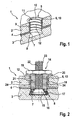
- FIG. 2 shows a mounting assembly 13 with the multi-layer body 1 from FIG. 1 and a fastening element 14.
- the fastening element 14 in the form of an undercut anchor, has a spreading region 15 at its front end in the direction of insertion, which engages in the undercut 8 in a stiffened state and fixes the fastening element 14 in the second bore 7 of the second layer 3.
- the fastening element has an expansion sleeve 16, which is pressed with an elastic cover 17 by means of a washer 18 in the undercut 8, in which the washer 18 is moved in the direction of forward, for example by screwing a nut 19.
- the washer 18 is made a collar 20, which rests on the outer side of the first layer 2 and covers the first bore 6, and a sleeve-shaped collar 21, which surrounds a bolt 22 with an external thread as load engagement means 23.
- On the bolt 22 is the mother 19 screwed.
- On the sleeve-shaped collar 21 elevations 24 are arranged, which correspond to the groove-like depressions 12 of the connecting sleeve 9 and are in engagement therewith.
- the elevations 24 have the shape of an external thread. Depending on the design of the groove-like depressions 12, their shape may deviate from this. Due to the connection between the connection sleeve 9 and the collar 21, the fastening element 14 is anchored in the first layer 2 on the one hand.
- FIG. 3 shows a variant of in FIG. 2 described mounting arrangement. To avoid repetition, the following is just to the differences to the in FIG. 2 received mounting arrangement.
- fastening assembly 13 ' has a multi-layer body 1 with a first bore 6 in the first layer 2, whose diameter is greater than the diameter of a second bore 7 in the second layer 3.
- the diameter of the second bore 7 corresponds to the outer diameter of the fastener 14th '. Due to the enlarged diameter of the first holes 6 dimensional tolerances resulting from the position of the holes 6, 7 and the borehole diameter can be compensated by the between the fastening element 14 and the wall 10 of the first bore 6 resulting annular gap 25.
- the fastening element 14 ' has a filling opening 26, which is arranged laterally on the collar 20' of the washer 18 'and extends radially therefrom. Through this filling opening 26, a filling compound 27 can be introduced into the annular gap 25, so that it is completely filled. By the filling compound 27, the connecting sleeve 9 is also connected to the sleeve-shaped collar 21 of the fastening element 14.
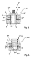
- FIG. 4 is a further mounting assembly 13 "shown with a multi-layer body 1", which differs from that in the FIGS. 1 3 is distinguished by the fact that the second bore 7 "penetrates the second layer 3.
- the second bore 7" is, however, furthermore designed with an undercut 8 "
- the fastening element 14" is an undercut anchor which penetrates through the multilayer body 1 "and the latter in the direction of insertion, the front end terminates flush with the outside of the second layer 3.
- the cylindrical part of the sleeve-shaped collar 21 is adjoined by a part with an enlarged diameter. This conical part fills the undercut 8 "in a form-fitting manner, so that the fastening element 14" is fastened in the fastening region 5 ".
- FIG. 5 a fastening arrangement 13 "'with a multilayer body 1'", the second layer 3 of which has a second bore 7 "', which is designed as a cylindrical through-hole
- the fastening element 14"' completely penetrates through the multilayer body 1 "'and becomes integral with the multilayer body 1 '' connected by the fact that the collar 20 '' and a Tarlegeteil 28, which is located in the insertion direction front end of the fastener 14 '', respectively on the outer sides of the first layer 2 and the second layer 3 rests.
- Both the collar 20 '''and the Auflegeteil 28 has a diameter which is greater than the diameter of the bores 6, 7''.
- FIG. 6 shows a fastening assembly according to the invention 13 "" during manufacture.
- the multilayer body 1 "" consists of a first layer 2, a second layer 3 and an intermediate layer 4, wherein each of the layers has a bore 6, 7 "", 29.
- the method for producing the fastening arrangement 13 “” provides that, in a first step, the first bore 6 of the first layer 2 is aligned with the second bore 7 "" of the second layer 3 and the third bore 29 of the intermediate layer 4. In a second step, the first layer 2 and the second layer 3 are then joined together by the intermediate layer 4. During or after these steps, the fastener 14 "" and the connecting sleeve 9 "" in the holes 6, 7 “", 29 introduced and connected to each other and with the multi-layer body 1 "".
- the connecting sleeve 9 "" can consist of several segments 30, which fill a gap between the wall 10 of the first bore 6 and the fastening element 14 "".
- the individual segments 30 of the connecting sleeve 9 "” are connected to each other, with the wall 10 of the first bore 6 and with the intermediate layer 4, wherein the Fastening element 14 "" with elevations 24 "” in the connecting sleeve 9 "” engages.
- a fastening arrangement 13 "" is provided, with which a breakage of the multilayer body 1 "", a Ausknüpfen the fastener 14 "" from the mounting portion 5 "” is prevented.
- Multi-layer body fastening arrangement, method for producing the fastening arrangement and fastening element
Landscapes
- Engineering & Computer Science (AREA)
- Architecture (AREA)
- Civil Engineering (AREA)
- Structural Engineering (AREA)
- Chemical & Material Sciences (AREA)
- Ceramic Engineering (AREA)
- Connection Of Plates (AREA)
Applications Claiming Priority (1)
| Application Number | Priority Date | Filing Date | Title |
|---|---|---|---|
| ITPD20070214 ITPD20070214A1 (it) | 2007-06-22 | 2007-06-22 | Pannello in vetro multistrato particolarmente del tipo vetro strutturale di sicurezza |
Publications (2)
| Publication Number | Publication Date |
|---|---|
| EP2006465A2 true EP2006465A2 (fr) | 2008-12-24 |
| EP2006465A3 EP2006465A3 (fr) | 2009-04-01 |
Family
ID=39775116
Family Applications (1)
| Application Number | Title | Priority Date | Filing Date |
|---|---|---|---|
| EP08010404A Withdrawn EP2006465A3 (fr) | 2007-06-22 | 2008-06-07 | Corps multicouche, dispositif de fixation, procédé de fabrication du dispositif de fixation et élément de fixation |
Country Status (2)
| Country | Link |
|---|---|
| EP (1) | EP2006465A3 (fr) |
| IT (1) | ITPD20070214A1 (fr) |
Cited By (9)
| Publication number | Priority date | Publication date | Assignee | Title |
|---|---|---|---|---|
| EP2075121A1 (fr) * | 2007-12-19 | 2009-07-01 | fischerwerke GmbH & Co. KG | Plaque améliorée en verre multicouche, notamment en verre de sécurité stratifié, et procédé de fabrication de celle-ci |
| DE202015105298U1 (de) * | 2015-10-07 | 2016-10-12 | Bergfelder Grundbesitz Gmbh & Co. Kg | Befestigungssystem und Befestigungsanker |
| US10148217B2 (en) | 2016-12-14 | 2018-12-04 | Solsera, Inc. | Structural attachment sealing system |
| US10562274B1 (en) * | 2016-02-22 | 2020-02-18 | Apple Inc. | Glass fastening and sealing systems |
| US10767684B1 (en) | 2019-04-26 | 2020-09-08 | Solsera, Inc. | Flat roof mounting device |
| US10781587B2 (en) | 2016-12-14 | 2020-09-22 | Solsera, Inc. | Structural attachment sealing system |
| US20220228425A1 (en) * | 2021-01-20 | 2022-07-21 | La Tecnica Nel Vetro S.P.A. | Structural, glass-aluminum facade component |
| US11746821B2 (en) | 2019-04-26 | 2023-09-05 | Solsera, Inc. | Flat roof mounting device |
| US11962137B2 (en) | 2020-04-21 | 2024-04-16 | Unirac Inc. | Electric junction box mount apparatus |
Citations (2)
| Publication number | Priority date | Publication date | Assignee | Title |
|---|---|---|---|---|
| EP0619435A1 (fr) | 1993-04-07 | 1994-10-12 | Saint-Gobain Vitrage | Fixation vissée d'un élément de retenue ou de fixation sur un vitrage feuilleté |
| WO2001088305A1 (fr) | 2000-05-13 | 2001-11-22 | Fischerwerke Arthur Fischer Gmbh & Co. Kg | Element de fixation pour un verre feuillete et agencement comportant l'element de fixation ancre dans un corps multicouche en forme de plaque |
Family Cites Families (2)
| Publication number | Priority date | Publication date | Assignee | Title |
|---|---|---|---|---|
| DE4223694C2 (de) * | 1992-07-21 | 1994-05-26 | Danz Robert | Konstruktions-Bauelement für die Verglasung von Bauten |
| DE29720458U1 (de) * | 1997-11-19 | 1998-01-22 | Wendker & Selders GmbH & Co Naturstein-Glas-Verbund KG, 45701 Herten | Stein- und/oder Glas-Verbundelement mit Hinterschnittdübel |
-
2007
- 2007-06-22 IT ITPD20070214 patent/ITPD20070214A1/it unknown
-
2008
- 2008-06-07 EP EP08010404A patent/EP2006465A3/fr not_active Withdrawn
Patent Citations (2)
| Publication number | Priority date | Publication date | Assignee | Title |
|---|---|---|---|---|
| EP0619435A1 (fr) | 1993-04-07 | 1994-10-12 | Saint-Gobain Vitrage | Fixation vissée d'un élément de retenue ou de fixation sur un vitrage feuilleté |
| WO2001088305A1 (fr) | 2000-05-13 | 2001-11-22 | Fischerwerke Arthur Fischer Gmbh & Co. Kg | Element de fixation pour un verre feuillete et agencement comportant l'element de fixation ancre dans un corps multicouche en forme de plaque |
Cited By (22)
| Publication number | Priority date | Publication date | Assignee | Title |
|---|---|---|---|---|
| EP2075121A1 (fr) * | 2007-12-19 | 2009-07-01 | fischerwerke GmbH & Co. KG | Plaque améliorée en verre multicouche, notamment en verre de sécurité stratifié, et procédé de fabrication de celle-ci |
| DE202015105298U1 (de) * | 2015-10-07 | 2016-10-12 | Bergfelder Grundbesitz Gmbh & Co. Kg | Befestigungssystem und Befestigungsanker |
| US11141950B1 (en) | 2016-02-22 | 2021-10-12 | Apple Inc. | Glass fastening and sealing systems |
| US11772354B1 (en) | 2016-02-22 | 2023-10-03 | Apple Inc. | Glass fastening and sealing systems |
| US10562274B1 (en) * | 2016-02-22 | 2020-02-18 | Apple Inc. | Glass fastening and sealing systems |
| US11486134B2 (en) | 2016-12-14 | 2022-11-01 | Unirac Inc. | Structural attachment sealing system |
| US12000137B2 (en) | 2016-12-14 | 2024-06-04 | Unirac Inc. | Structural attachment sealing system |
| US10781587B2 (en) | 2016-12-14 | 2020-09-22 | Solsera, Inc. | Structural attachment sealing system |
| US10982430B2 (en) | 2016-12-14 | 2021-04-20 | Solsera, Inc. | Structural attachment sealing system |
| US11486133B2 (en) | 2016-12-14 | 2022-11-01 | Unirac Inc. | Structural attachment sealing system |
| US12024880B2 (en) | 2016-12-14 | 2024-07-02 | Unirac Inc. | Structural attachment sealing system |
| US11572690B2 (en) | 2016-12-14 | 2023-02-07 | Unirac Inc. | Structural attachment sealing system |
| US12018476B2 (en) | 2016-12-14 | 2024-06-25 | Unirac Inc. | Structural attachment sealing system |
| US10148217B2 (en) | 2016-12-14 | 2018-12-04 | Solsera, Inc. | Structural attachment sealing system |
| US12085112B2 (en) | 2019-04-26 | 2024-09-10 | Solsera, Inc. | Flat roof mounting device |
| US11746821B2 (en) | 2019-04-26 | 2023-09-05 | Solsera, Inc. | Flat roof mounting device |
| US10767684B1 (en) | 2019-04-26 | 2020-09-08 | Solsera, Inc. | Flat roof mounting device |
| US12163552B2 (en) | 2019-04-26 | 2024-12-10 | Solsera, Inc. | Flat roof mounting device |
| US11962137B2 (en) | 2020-04-21 | 2024-04-16 | Unirac Inc. | Electric junction box mount apparatus |
| US12494627B2 (en) | 2020-04-21 | 2025-12-09 | Unirac, Inc. | Electric junction box mount apparatus |
| US20220228425A1 (en) * | 2021-01-20 | 2022-07-21 | La Tecnica Nel Vetro S.P.A. | Structural, glass-aluminum facade component |
| US12534952B2 (en) * | 2021-01-20 | 2026-01-27 | La Tecnica Nel Vetro S.P.A. | Structural, glass-aluminum facade component |
Also Published As
| Publication number | Publication date |
|---|---|
| ITPD20070214A1 (it) | 2008-12-23 |
| EP2006465A3 (fr) | 2009-04-01 |
Similar Documents
| Publication | Publication Date | Title |
|---|---|---|
| EP2006465A2 (fr) | Corps multicouche, dispositif de fixation, procédé de fabrication du dispositif de fixation et élément de fixation | |
| EP2802487B1 (fr) | Structure porteuse absorbant l'énergie et procédé de fabrication de ladite structure | |
| EP1283931B1 (fr) | Elément de fixation pour un corps multicouche en forme de plaque, en particulier un verre feuilleté ou un panneau solaire, et agencement comportant cet élément de fixation ancré dans un tel corps | |
| EP2082143B1 (fr) | Association composée d'une vis, d'une rondelle et d'une douille, et procédé de production d'une telle combinaison | |
| DE102012001086A1 (de) | Bolzenelement und Verfahren zur Anbringung eines Bolzenelements an einem Bauteil aus einem Verbundwerkstoff | |
| EP2283231A1 (fr) | Procédé de fabrication d'un raccord de pale de rotor, raccord de pale et élément de fixation pour un raccord de pale | |
| DE102014204449A1 (de) | Verfahren zum Verbinden von Bauteilen von denen eines aus einem faserverstärkten Kunststoff besteht | |
| WO2016015969A1 (fr) | Dispositif de fixation d'un élément structural en sandwich | |
| EP2484924A1 (fr) | Liaison bout à bout et procédé de développement d'une liaison bout à bout | |
| EP0534001B1 (fr) | Assemblage à vis pour assembler deux pièces de construction, qui ont vue distance, notamment des plaques de métal | |
| EP3228879B1 (fr) | Ferrure d'assemblage, système et procédé d'assemblage de deux panneaux de construction légers | |
| EP3599385B1 (fr) | Boulon de verrouillage à billes à blocage au voisinage de la tête | |
| DE102009053848A1 (de) | Nagel zum Eintreiben in mindestens ein nicht vorgelochtes Bauteil | |
| DE102012001943B4 (de) | Verfahren zum Herstellen eines rohrförmigen rotationssymmetrischen Kfz-Fahrwerkbauteils wie einer Kolbenstange, und zusammengesetzte Kolbenstange | |
| EP2083179B1 (fr) | Elément de liaison | |
| WO2016202876A1 (fr) | Élément de liaison à friction thermoplastique | |
| EP4040927A1 (fr) | Module comprenant une platine et une partie de base | |
| WO2014108240A1 (fr) | Procédé de fabrication d'un composant structurel d'un véhicule | |
| DE102012202331A1 (de) | Buchse zur Lochverstärkung in einem Bauteil | |
| DE102009044770A1 (de) | Befestigungselement und Befestigungsanordnung | |
| EP3839271B1 (fr) | Goujon destiné à être agencé dans des plaques de construction légère, procédé de fixation et un agencement. | |
| DE202004001980U1 (de) | Vorrichtung zum Verbinden von Bauelementen | |
| DE10063547C1 (de) | Verbundscheibe, insbesondere für eine Glasbonstruktion | |
| DE102017126056A1 (de) | Verfahren zum Befestigen eines Dämmstoffelements und Dämmstoffdübel | |
| EP3865719A1 (fr) | Unité comprenant un élément de fixation et une pièce d'insert et procédé de fabrication d'un élément pourvu de l'unité |
Legal Events
| Date | Code | Title | Description |
|---|---|---|---|
| PUAI | Public reference made under article 153(3) epc to a published international application that has entered the european phase |
Free format text: ORIGINAL CODE: 0009012 |
|
| AK | Designated contracting states |
Kind code of ref document: A2 Designated state(s): AT BE BG CH CY CZ DE DK EE ES FI FR GB GR HR HU IE IS IT LI LT LU LV MC MT NL NO PL PT RO SE SI SK TR |
|
| AX | Request for extension of the european patent |
Extension state: AL BA MK RS |
|
| PUAL | Search report despatched |
Free format text: ORIGINAL CODE: 0009013 |
|
| AK | Designated contracting states |
Kind code of ref document: A3 Designated state(s): AT BE BG CH CY CZ DE DK EE ES FI FR GB GR HR HU IE IS IT LI LT LU LV MC MT NL NO PL PT RO SE SI SK TR |
|
| AX | Request for extension of the european patent |
Extension state: AL BA MK RS |
|
| 17Q | First examination report despatched |
Effective date: 20090925 |
|
| 17P | Request for examination filed |
Effective date: 20090831 |
|
| AKX | Designation fees paid |
Designated state(s): AT BE BG CH CY CZ DE DK EE ES FI FR GB GR HR HU IE IS IT LI LT LU LV MC MT NL NO PL PT RO SE SI SK TR |
|
| GRAP | Despatch of communication of intention to grant a patent |
Free format text: ORIGINAL CODE: EPIDOSNIGR1 |
|
| STAA | Information on the status of an ep patent application or granted ep patent |
Free format text: STATUS: THE APPLICATION IS DEEMED TO BE WITHDRAWN |
|
| 18D | Application deemed to be withdrawn |
Effective date: 20130625 |