EP3865719A1 - Unité comprenant un élément de fixation et une pièce d'insert et procédé de fabrication d'un élément pourvu de l'unité - Google Patents
Unité comprenant un élément de fixation et une pièce d'insert et procédé de fabrication d'un élément pourvu de l'unité Download PDFInfo
- Publication number
- EP3865719A1 EP3865719A1 EP20210583.9A EP20210583A EP3865719A1 EP 3865719 A1 EP3865719 A1 EP 3865719A1 EP 20210583 A EP20210583 A EP 20210583A EP 3865719 A1 EP3865719 A1 EP 3865719A1
- Authority
- EP
- European Patent Office
- Prior art keywords
- blind hole
- fixing element
- insert
- assembly
- component
- Prior art date
- Legal status (The legal status is an assumption and is not a legal conclusion. Google has not performed a legal analysis and makes no representation as to the accuracy of the status listed.)
- Withdrawn
Links
- 238000004519 manufacturing process Methods 0.000 title claims description 8
- 239000000463 material Substances 0.000 claims description 24
- 238000000034 method Methods 0.000 claims description 13
- 239000000853 adhesive Substances 0.000 claims description 11
- 230000001070 adhesive effect Effects 0.000 claims description 11
- 239000002184 metal Substances 0.000 claims description 8
- 238000001746 injection moulding Methods 0.000 claims description 5
- 239000000155 melt Substances 0.000 description 10
- 238000003466 welding Methods 0.000 description 6
- 230000007704 transition Effects 0.000 description 5
- 238000011161 development Methods 0.000 description 4
- 230000018109 developmental process Effects 0.000 description 4
- 230000000694 effects Effects 0.000 description 4
- 239000012530 fluid Substances 0.000 description 3
- 238000003780 insertion Methods 0.000 description 3
- 230000037431 insertion Effects 0.000 description 3
- 238000002604 ultrasonography Methods 0.000 description 3
- 238000007711 solidification Methods 0.000 description 2
- 230000008023 solidification Effects 0.000 description 2
- 238000004026 adhesive bonding Methods 0.000 description 1
- 229920005601 base polymer Polymers 0.000 description 1
- 238000010586 diagram Methods 0.000 description 1
- 238000007765 extrusion coating Methods 0.000 description 1
- 230000002349 favourable effect Effects 0.000 description 1
- 239000007789 gas Substances 0.000 description 1
- 230000000717 retained effect Effects 0.000 description 1
- 239000013589 supplement Substances 0.000 description 1
Images
Classifications
-
- F—MECHANICAL ENGINEERING; LIGHTING; HEATING; WEAPONS; BLASTING
- F16—ENGINEERING ELEMENTS AND UNITS; GENERAL MEASURES FOR PRODUCING AND MAINTAINING EFFECTIVE FUNCTIONING OF MACHINES OR INSTALLATIONS; THERMAL INSULATION IN GENERAL
- F16B—DEVICES FOR FASTENING OR SECURING CONSTRUCTIONAL ELEMENTS OR MACHINE PARTS TOGETHER, e.g. NAILS, BOLTS, CIRCLIPS, CLAMPS, CLIPS OR WEDGES; JOINTS OR JOINTING
- F16B37/00—Nuts or like thread-engaging members
- F16B37/12—Nuts or like thread-engaging members with thread-engaging surfaces formed by inserted coil-springs, discs, or the like; Independent pieces of wound wire used as nuts; Threaded inserts for holes
- F16B37/122—Threaded inserts, e.g. "rampa bolts"
-
- B—PERFORMING OPERATIONS; TRANSPORTING
- B29—WORKING OF PLASTICS; WORKING OF SUBSTANCES IN A PLASTIC STATE IN GENERAL
- B29C—SHAPING OR JOINING OF PLASTICS; SHAPING OF MATERIAL IN A PLASTIC STATE, NOT OTHERWISE PROVIDED FOR; AFTER-TREATMENT OF THE SHAPED PRODUCTS, e.g. REPAIRING
- B29C65/00—Joining or sealing of preformed parts, e.g. welding of plastics materials; Apparatus therefor
- B29C65/02—Joining or sealing of preformed parts, e.g. welding of plastics materials; Apparatus therefor by heating, with or without pressure
-
- B—PERFORMING OPERATIONS; TRANSPORTING
- B29—WORKING OF PLASTICS; WORKING OF SUBSTANCES IN A PLASTIC STATE IN GENERAL
- B29C—SHAPING OR JOINING OF PLASTICS; SHAPING OF MATERIAL IN A PLASTIC STATE, NOT OTHERWISE PROVIDED FOR; AFTER-TREATMENT OF THE SHAPED PRODUCTS, e.g. REPAIRING
- B29C65/00—Joining or sealing of preformed parts, e.g. welding of plastics materials; Apparatus therefor
- B29C65/02—Joining or sealing of preformed parts, e.g. welding of plastics materials; Apparatus therefor by heating, with or without pressure
- B29C65/06—Joining or sealing of preformed parts, e.g. welding of plastics materials; Apparatus therefor by heating, with or without pressure using friction, e.g. spin welding
-
- B—PERFORMING OPERATIONS; TRANSPORTING
- B29—WORKING OF PLASTICS; WORKING OF SUBSTANCES IN A PLASTIC STATE IN GENERAL
- B29C—SHAPING OR JOINING OF PLASTICS; SHAPING OF MATERIAL IN A PLASTIC STATE, NOT OTHERWISE PROVIDED FOR; AFTER-TREATMENT OF THE SHAPED PRODUCTS, e.g. REPAIRING
- B29C65/00—Joining or sealing of preformed parts, e.g. welding of plastics materials; Apparatus therefor
- B29C65/02—Joining or sealing of preformed parts, e.g. welding of plastics materials; Apparatus therefor by heating, with or without pressure
- B29C65/08—Joining or sealing of preformed parts, e.g. welding of plastics materials; Apparatus therefor by heating, with or without pressure using ultrasonic vibrations
-
- B—PERFORMING OPERATIONS; TRANSPORTING
- B29—WORKING OF PLASTICS; WORKING OF SUBSTANCES IN A PLASTIC STATE IN GENERAL
- B29C—SHAPING OR JOINING OF PLASTICS; SHAPING OF MATERIAL IN A PLASTIC STATE, NOT OTHERWISE PROVIDED FOR; AFTER-TREATMENT OF THE SHAPED PRODUCTS, e.g. REPAIRING
- B29C66/00—General aspects of processes or apparatus for joining preformed parts
- B29C66/01—General aspects dealing with the joint area or with the area to be joined
- B29C66/05—Particular design of joint configurations
- B29C66/10—Particular design of joint configurations particular design of the joint cross-sections
- B29C66/11—Joint cross-sections comprising a single joint-segment, i.e. one of the parts to be joined comprising a single joint-segment in the joint cross-section
- B29C66/112—Single lapped joints
- B29C66/1122—Single lap to lap joints, i.e. overlap joints
-
- B—PERFORMING OPERATIONS; TRANSPORTING
- B29—WORKING OF PLASTICS; WORKING OF SUBSTANCES IN A PLASTIC STATE IN GENERAL
- B29C—SHAPING OR JOINING OF PLASTICS; SHAPING OF MATERIAL IN A PLASTIC STATE, NOT OTHERWISE PROVIDED FOR; AFTER-TREATMENT OF THE SHAPED PRODUCTS, e.g. REPAIRING
- B29C66/00—General aspects of processes or apparatus for joining preformed parts
- B29C66/01—General aspects dealing with the joint area or with the area to be joined
- B29C66/05—Particular design of joint configurations
- B29C66/10—Particular design of joint configurations particular design of the joint cross-sections
- B29C66/12—Joint cross-sections combining only two joint-segments; Tongue and groove joints; Tenon and mortise joints; Stepped joint cross-sections
- B29C66/122—Joint cross-sections combining only two joint-segments, i.e. one of the parts to be joined comprising only two joint-segments in the joint cross-section
- B29C66/1222—Joint cross-sections combining only two joint-segments, i.e. one of the parts to be joined comprising only two joint-segments in the joint cross-section comprising at least a lapped joint-segment
-
- B—PERFORMING OPERATIONS; TRANSPORTING
- B29—WORKING OF PLASTICS; WORKING OF SUBSTANCES IN A PLASTIC STATE IN GENERAL
- B29C—SHAPING OR JOINING OF PLASTICS; SHAPING OF MATERIAL IN A PLASTIC STATE, NOT OTHERWISE PROVIDED FOR; AFTER-TREATMENT OF THE SHAPED PRODUCTS, e.g. REPAIRING
- B29C66/00—General aspects of processes or apparatus for joining preformed parts
- B29C66/01—General aspects dealing with the joint area or with the area to be joined
- B29C66/05—Particular design of joint configurations
- B29C66/10—Particular design of joint configurations particular design of the joint cross-sections
- B29C66/12—Joint cross-sections combining only two joint-segments; Tongue and groove joints; Tenon and mortise joints; Stepped joint cross-sections
- B29C66/122—Joint cross-sections combining only two joint-segments, i.e. one of the parts to be joined comprising only two joint-segments in the joint cross-section
- B29C66/1224—Joint cross-sections combining only two joint-segments, i.e. one of the parts to be joined comprising only two joint-segments in the joint cross-section comprising at least a butt joint-segment
-
- B—PERFORMING OPERATIONS; TRANSPORTING
- B29—WORKING OF PLASTICS; WORKING OF SUBSTANCES IN A PLASTIC STATE IN GENERAL
- B29C—SHAPING OR JOINING OF PLASTICS; SHAPING OF MATERIAL IN A PLASTIC STATE, NOT OTHERWISE PROVIDED FOR; AFTER-TREATMENT OF THE SHAPED PRODUCTS, e.g. REPAIRING
- B29C66/00—General aspects of processes or apparatus for joining preformed parts
- B29C66/01—General aspects dealing with the joint area or with the area to be joined
- B29C66/05—Particular design of joint configurations
- B29C66/10—Particular design of joint configurations particular design of the joint cross-sections
- B29C66/12—Joint cross-sections combining only two joint-segments; Tongue and groove joints; Tenon and mortise joints; Stepped joint cross-sections
- B29C66/128—Stepped joint cross-sections
- B29C66/1282—Stepped joint cross-sections comprising at least one overlap joint-segment
- B29C66/12821—Stepped joint cross-sections comprising at least one overlap joint-segment comprising at least two overlap joint-segments
-
- B—PERFORMING OPERATIONS; TRANSPORTING
- B29—WORKING OF PLASTICS; WORKING OF SUBSTANCES IN A PLASTIC STATE IN GENERAL
- B29C—SHAPING OR JOINING OF PLASTICS; SHAPING OF MATERIAL IN A PLASTIC STATE, NOT OTHERWISE PROVIDED FOR; AFTER-TREATMENT OF THE SHAPED PRODUCTS, e.g. REPAIRING
- B29C66/00—General aspects of processes or apparatus for joining preformed parts
- B29C66/01—General aspects dealing with the joint area or with the area to be joined
- B29C66/05—Particular design of joint configurations
- B29C66/10—Particular design of joint configurations particular design of the joint cross-sections
- B29C66/12—Joint cross-sections combining only two joint-segments; Tongue and groove joints; Tenon and mortise joints; Stepped joint cross-sections
- B29C66/128—Stepped joint cross-sections
- B29C66/1284—Stepped joint cross-sections comprising at least one butt joint-segment
-
- B—PERFORMING OPERATIONS; TRANSPORTING
- B29—WORKING OF PLASTICS; WORKING OF SUBSTANCES IN A PLASTIC STATE IN GENERAL
- B29C—SHAPING OR JOINING OF PLASTICS; SHAPING OF MATERIAL IN A PLASTIC STATE, NOT OTHERWISE PROVIDED FOR; AFTER-TREATMENT OF THE SHAPED PRODUCTS, e.g. REPAIRING
- B29C66/00—General aspects of processes or apparatus for joining preformed parts
- B29C66/01—General aspects dealing with the joint area or with the area to be joined
- B29C66/05—Particular design of joint configurations
- B29C66/302—Particular design of joint configurations the area to be joined comprising melt initiators
- B29C66/3022—Particular design of joint configurations the area to be joined comprising melt initiators said melt initiators being integral with at least one of the parts to be joined
- B29C66/30223—Particular design of joint configurations the area to be joined comprising melt initiators said melt initiators being integral with at least one of the parts to be joined said melt initiators being rib-like
-
- B—PERFORMING OPERATIONS; TRANSPORTING
- B29—WORKING OF PLASTICS; WORKING OF SUBSTANCES IN A PLASTIC STATE IN GENERAL
- B29C—SHAPING OR JOINING OF PLASTICS; SHAPING OF MATERIAL IN A PLASTIC STATE, NOT OTHERWISE PROVIDED FOR; AFTER-TREATMENT OF THE SHAPED PRODUCTS, e.g. REPAIRING
- B29C66/00—General aspects of processes or apparatus for joining preformed parts
- B29C66/40—General aspects of joining substantially flat articles, e.g. plates, sheets or web-like materials; Making flat seams in tubular or hollow articles; Joining single elements to substantially flat surfaces
- B29C66/47—Joining single elements to sheets, plates or other substantially flat surfaces
- B29C66/474—Joining single elements to sheets, plates or other substantially flat surfaces said single elements being substantially non-flat
-
- B—PERFORMING OPERATIONS; TRANSPORTING
- B29—WORKING OF PLASTICS; WORKING OF SUBSTANCES IN A PLASTIC STATE IN GENERAL
- B29C—SHAPING OR JOINING OF PLASTICS; SHAPING OF MATERIAL IN A PLASTIC STATE, NOT OTHERWISE PROVIDED FOR; AFTER-TREATMENT OF THE SHAPED PRODUCTS, e.g. REPAIRING
- B29C66/00—General aspects of processes or apparatus for joining preformed parts
- B29C66/50—General aspects of joining tubular articles; General aspects of joining long products, i.e. bars or profiled elements; General aspects of joining single elements to tubular articles, hollow articles or bars; General aspects of joining several hollow-preforms to form hollow or tubular articles
- B29C66/51—Joining tubular articles, profiled elements or bars; Joining single elements to tubular articles, hollow articles or bars; Joining several hollow-preforms to form hollow or tubular articles
- B29C66/53—Joining single elements to tubular articles, hollow articles or bars
- B29C66/532—Joining single elements to the wall of tubular articles, hollow articles or bars
- B29C66/5324—Joining single elements to the wall of tubular articles, hollow articles or bars said single elements being substantially annular, i.e. of finite length
-
- B—PERFORMING OPERATIONS; TRANSPORTING
- B29—WORKING OF PLASTICS; WORKING OF SUBSTANCES IN A PLASTIC STATE IN GENERAL
- B29C—SHAPING OR JOINING OF PLASTICS; SHAPING OF MATERIAL IN A PLASTIC STATE, NOT OTHERWISE PROVIDED FOR; AFTER-TREATMENT OF THE SHAPED PRODUCTS, e.g. REPAIRING
- B29C66/00—General aspects of processes or apparatus for joining preformed parts
- B29C66/50—General aspects of joining tubular articles; General aspects of joining long products, i.e. bars or profiled elements; General aspects of joining single elements to tubular articles, hollow articles or bars; General aspects of joining several hollow-preforms to form hollow or tubular articles
- B29C66/51—Joining tubular articles, profiled elements or bars; Joining single elements to tubular articles, hollow articles or bars; Joining several hollow-preforms to form hollow or tubular articles
- B29C66/53—Joining single elements to tubular articles, hollow articles or bars
- B29C66/534—Joining single elements to open ends of tubular or hollow articles or to the ends of bars
- B29C66/5344—Joining single elements to open ends of tubular or hollow articles or to the ends of bars said single elements being substantially annular, i.e. of finite length, e.g. joining flanges to tube ends
-
- B—PERFORMING OPERATIONS; TRANSPORTING
- B29—WORKING OF PLASTICS; WORKING OF SUBSTANCES IN A PLASTIC STATE IN GENERAL
- B29C—SHAPING OR JOINING OF PLASTICS; SHAPING OF MATERIAL IN A PLASTIC STATE, NOT OTHERWISE PROVIDED FOR; AFTER-TREATMENT OF THE SHAPED PRODUCTS, e.g. REPAIRING
- B29C66/00—General aspects of processes or apparatus for joining preformed parts
- B29C66/70—General aspects of processes or apparatus for joining preformed parts characterised by the composition, physical properties or the structure of the material of the parts to be joined; Joining with non-plastics material
- B29C66/71—General aspects of processes or apparatus for joining preformed parts characterised by the composition, physical properties or the structure of the material of the parts to be joined; Joining with non-plastics material characterised by the composition of the plastics material of the parts to be joined
-
- B—PERFORMING OPERATIONS; TRANSPORTING
- B29—WORKING OF PLASTICS; WORKING OF SUBSTANCES IN A PLASTIC STATE IN GENERAL
- B29C—SHAPING OR JOINING OF PLASTICS; SHAPING OF MATERIAL IN A PLASTIC STATE, NOT OTHERWISE PROVIDED FOR; AFTER-TREATMENT OF THE SHAPED PRODUCTS, e.g. REPAIRING
- B29C66/00—General aspects of processes or apparatus for joining preformed parts
- B29C66/70—General aspects of processes or apparatus for joining preformed parts characterised by the composition, physical properties or the structure of the material of the parts to be joined; Joining with non-plastics material
- B29C66/72—General aspects of processes or apparatus for joining preformed parts characterised by the composition, physical properties or the structure of the material of the parts to be joined; Joining with non-plastics material characterised by the structure of the material of the parts to be joined
- B29C66/721—Fibre-reinforced materials
- B29C66/7212—Fibre-reinforced materials characterised by the composition of the fibres
-
- B—PERFORMING OPERATIONS; TRANSPORTING
- B29—WORKING OF PLASTICS; WORKING OF SUBSTANCES IN A PLASTIC STATE IN GENERAL
- B29C—SHAPING OR JOINING OF PLASTICS; SHAPING OF MATERIAL IN A PLASTIC STATE, NOT OTHERWISE PROVIDED FOR; AFTER-TREATMENT OF THE SHAPED PRODUCTS, e.g. REPAIRING
- B29C66/00—General aspects of processes or apparatus for joining preformed parts
- B29C66/70—General aspects of processes or apparatus for joining preformed parts characterised by the composition, physical properties or the structure of the material of the parts to be joined; Joining with non-plastics material
- B29C66/72—General aspects of processes or apparatus for joining preformed parts characterised by the composition, physical properties or the structure of the material of the parts to be joined; Joining with non-plastics material characterised by the structure of the material of the parts to be joined
- B29C66/721—Fibre-reinforced materials
- B29C66/7214—Fibre-reinforced materials characterised by the length of the fibres
- B29C66/72143—Fibres of discontinuous lengths
-
- B—PERFORMING OPERATIONS; TRANSPORTING
- B29—WORKING OF PLASTICS; WORKING OF SUBSTANCES IN A PLASTIC STATE IN GENERAL
- B29C—SHAPING OR JOINING OF PLASTICS; SHAPING OF MATERIAL IN A PLASTIC STATE, NOT OTHERWISE PROVIDED FOR; AFTER-TREATMENT OF THE SHAPED PRODUCTS, e.g. REPAIRING
- B29C66/00—General aspects of processes or apparatus for joining preformed parts
- B29C66/70—General aspects of processes or apparatus for joining preformed parts characterised by the composition, physical properties or the structure of the material of the parts to be joined; Joining with non-plastics material
- B29C66/73—General aspects of processes or apparatus for joining preformed parts characterised by the composition, physical properties or the structure of the material of the parts to be joined; Joining with non-plastics material characterised by the intensive physical properties of the material of the parts to be joined, by the optical properties of the material of the parts to be joined, by the extensive physical properties of the parts to be joined, by the state of the material of the parts to be joined or by the material of the parts to be joined being a thermoplastic or a thermoset
- B29C66/739—General aspects of processes or apparatus for joining preformed parts characterised by the composition, physical properties or the structure of the material of the parts to be joined; Joining with non-plastics material characterised by the intensive physical properties of the material of the parts to be joined, by the optical properties of the material of the parts to be joined, by the extensive physical properties of the parts to be joined, by the state of the material of the parts to be joined or by the material of the parts to be joined being a thermoplastic or a thermoset characterised by the material of the parts to be joined being a thermoplastic or a thermoset
- B29C66/7392—General aspects of processes or apparatus for joining preformed parts characterised by the composition, physical properties or the structure of the material of the parts to be joined; Joining with non-plastics material characterised by the intensive physical properties of the material of the parts to be joined, by the optical properties of the material of the parts to be joined, by the extensive physical properties of the parts to be joined, by the state of the material of the parts to be joined or by the material of the parts to be joined being a thermoplastic or a thermoset characterised by the material of the parts to be joined being a thermoplastic or a thermoset characterised by the material of at least one of the parts being a thermoplastic
-
- B—PERFORMING OPERATIONS; TRANSPORTING
- B29—WORKING OF PLASTICS; WORKING OF SUBSTANCES IN A PLASTIC STATE IN GENERAL
- B29C—SHAPING OR JOINING OF PLASTICS; SHAPING OF MATERIAL IN A PLASTIC STATE, NOT OTHERWISE PROVIDED FOR; AFTER-TREATMENT OF THE SHAPED PRODUCTS, e.g. REPAIRING
- B29C66/00—General aspects of processes or apparatus for joining preformed parts
- B29C66/70—General aspects of processes or apparatus for joining preformed parts characterised by the composition, physical properties or the structure of the material of the parts to be joined; Joining with non-plastics material
- B29C66/73—General aspects of processes or apparatus for joining preformed parts characterised by the composition, physical properties or the structure of the material of the parts to be joined; Joining with non-plastics material characterised by the intensive physical properties of the material of the parts to be joined, by the optical properties of the material of the parts to be joined, by the extensive physical properties of the parts to be joined, by the state of the material of the parts to be joined or by the material of the parts to be joined being a thermoplastic or a thermoset
- B29C66/739—General aspects of processes or apparatus for joining preformed parts characterised by the composition, physical properties or the structure of the material of the parts to be joined; Joining with non-plastics material characterised by the intensive physical properties of the material of the parts to be joined, by the optical properties of the material of the parts to be joined, by the extensive physical properties of the parts to be joined, by the state of the material of the parts to be joined or by the material of the parts to be joined being a thermoplastic or a thermoset characterised by the material of the parts to be joined being a thermoplastic or a thermoset
- B29C66/7392—General aspects of processes or apparatus for joining preformed parts characterised by the composition, physical properties or the structure of the material of the parts to be joined; Joining with non-plastics material characterised by the intensive physical properties of the material of the parts to be joined, by the optical properties of the material of the parts to be joined, by the extensive physical properties of the parts to be joined, by the state of the material of the parts to be joined or by the material of the parts to be joined being a thermoplastic or a thermoset characterised by the material of the parts to be joined being a thermoplastic or a thermoset characterised by the material of at least one of the parts being a thermoplastic
- B29C66/73921—General aspects of processes or apparatus for joining preformed parts characterised by the composition, physical properties or the structure of the material of the parts to be joined; Joining with non-plastics material characterised by the intensive physical properties of the material of the parts to be joined, by the optical properties of the material of the parts to be joined, by the extensive physical properties of the parts to be joined, by the state of the material of the parts to be joined or by the material of the parts to be joined being a thermoplastic or a thermoset characterised by the material of the parts to be joined being a thermoplastic or a thermoset characterised by the material of at least one of the parts being a thermoplastic characterised by the materials of both parts being thermoplastics
-
- B—PERFORMING OPERATIONS; TRANSPORTING
- B29—WORKING OF PLASTICS; WORKING OF SUBSTANCES IN A PLASTIC STATE IN GENERAL
- B29C—SHAPING OR JOINING OF PLASTICS; SHAPING OF MATERIAL IN A PLASTIC STATE, NOT OTHERWISE PROVIDED FOR; AFTER-TREATMENT OF THE SHAPED PRODUCTS, e.g. REPAIRING
- B29C66/00—General aspects of processes or apparatus for joining preformed parts
- B29C66/70—General aspects of processes or apparatus for joining preformed parts characterised by the composition, physical properties or the structure of the material of the parts to be joined; Joining with non-plastics material
- B29C66/74—Joining plastics material to non-plastics material
- B29C66/742—Joining plastics material to non-plastics material to metals or their alloys
-
- F—MECHANICAL ENGINEERING; LIGHTING; HEATING; WEAPONS; BLASTING
- F16—ENGINEERING ELEMENTS AND UNITS; GENERAL MEASURES FOR PRODUCING AND MAINTAINING EFFECTIVE FUNCTIONING OF MACHINES OR INSTALLATIONS; THERMAL INSULATION IN GENERAL
- F16B—DEVICES FOR FASTENING OR SECURING CONSTRUCTIONAL ELEMENTS OR MACHINE PARTS TOGETHER, e.g. NAILS, BOLTS, CIRCLIPS, CLAMPS, CLIPS OR WEDGES; JOINTS OR JOINTING
- F16B37/00—Nuts or like thread-engaging members
- F16B37/04—Devices for fastening nuts to surfaces, e.g. sheets, plates
- F16B37/06—Devices for fastening nuts to surfaces, e.g. sheets, plates by means of welding or riveting
- F16B37/061—Devices for fastening nuts to surfaces, e.g. sheets, plates by means of welding or riveting by means of welding
-
- B—PERFORMING OPERATIONS; TRANSPORTING
- B29—WORKING OF PLASTICS; WORKING OF SUBSTANCES IN A PLASTIC STATE IN GENERAL
- B29L—INDEXING SCHEME ASSOCIATED WITH SUBCLASS B29C, RELATING TO PARTICULAR ARTICLES
- B29L2001/00—Articles provided with screw threads
- B29L2001/005—Nuts
-
- F—MECHANICAL ENGINEERING; LIGHTING; HEATING; WEAPONS; BLASTING
- F16—ENGINEERING ELEMENTS AND UNITS; GENERAL MEASURES FOR PRODUCING AND MAINTAINING EFFECTIVE FUNCTIONING OF MACHINES OR INSTALLATIONS; THERMAL INSULATION IN GENERAL
- F16B—DEVICES FOR FASTENING OR SECURING CONSTRUCTIONAL ELEMENTS OR MACHINE PARTS TOGETHER, e.g. NAILS, BOLTS, CIRCLIPS, CLAMPS, CLIPS OR WEDGES; JOINTS OR JOINTING
- F16B33/00—Features common to bolt and nut
- F16B33/002—Means for preventing rotation of screw-threaded elements
Definitions
- the invention relates to an assembly comprising a fixing element and an insert and a method for producing a component with the assembly.
- Components that are intended for use with fluids have chambers and cavities in which the fluids are stored or flow.
- Such components can be, for example, air spring volumes which influence the spring characteristics of an air spring.
- Fluids can in particular gases, such as. B. air.
- through openings can be made through the walls of the components to attach these components to other components in order to insert metal inserts for fasteners.
- the metal insert can also have through openings, so that there can be a leakage between the fastening means and the metal insert.
- the threaded insert has a collar with an adhesive device.
- the collar is connected to a countersink in the opening by means of the adhesive device in order to seal the area between the threaded insert and the oil pan.
- this is associated with a great deal of effort.
- the object of the invention can therefore be to provide an improved device which creates a tensile and gas-tight connection between a component and an insert with little effort.
- an assembly comprising a fixing element and an insert piece
- the fixing element comprising a receiving area extending between an inner side and an outer side of the fixing element for receiving an insert piece, the inner side being designed to be arranged in a blind hole
- the Insert has a contact area which extends along a longitudinal axis of the receiving area along the receiving area, the insert having a collar element connected to the contact area, at least partially extending around the longitudinal axis, arranged on the inside and having a first diameter which is larger than a second diameter of the receiving area and forms a form fit with the fixing element in the direction of the longitudinal axis
- the fixing element has a connection area for connecting to a component, which extends around the longitudinal axis along an outer En surface of the fixing element extends.
- the invention provides an assembly in which a fixing element supplements an insert piece, which has a collar element, to such an extent that the insert piece can be fastened in a blind hole of a component.
- the collar element is secured against being torn out of the component by the fixing element.
- the fixing element has a receiving area which is designed to receive the insert.
- the receiving area extends between an inner side and an outer side of the fixing element and can, for example, be a through opening.
- the inside is designed so that it can be arranged inside a blind hole.
- the insert piece is arranged with a contact area in the receiving area, the contact area extending along a longitudinal axis of the receiving area.
- the insert piece comprises a collar element which is arranged on the inside of the insert piece and which is itself at least partially around the longitudinal axis.
- the collar element has a form fit with the fixing element in the direction of the longitudinal axis. That is to say that the collar element, which is arranged on the inside, blocks a movement of the insert piece in the direction of the outside.
- the fixing element also has a connection area with which the entire assembly can be connected to the component material within a blind hole of a component.
- the blind hole can be formed in one piece with the rest of the assembly, for example milled into it or preferably formed off-tool by means of injection molding within the assembly.
- the connection area extends along an outer surface of the fixing element.
- the fixing element thus connects the insert piece to the component, the collar element of the insert piece being able to be arranged within a blind hole so that the fixing element forms a form fit with the collar element.
- the collar element is thus attached within the blind hole.
- the contact area is embedded in a plastic melt that is arranged in the receiving area and is connected to the fixing element in a form-fitting manner and that was formed during the embedding, preferably by means of ultrasonic embedding, and then solidified.
- the plastic melt which is arranged between the fixing element and the insert piece on the receiving area, a connection between the fixing element and the insert piece is brought about, which can be established without great effort. If the connection is created by means of ultrasonic embedding, this further simplifies the connection of the insert to the fixing element.
- the plastic melt can consist of the material of the fixing element and can first be melted during the connection process in order to flow into the contact area of the insert. After solidification, the plastic melt connects the contact area with the receiving area by means of a form fit and fixes the insert on the fixing element.
- the contact area can be pressed or plugged into the receiving area, the contact area having a third diameter that is greater than the second diameter or equal to the second diameter.
- the contact area thus has at least the same diameter as the receiving area. If the contact area has a larger third diameter on average than the receiving area, then the third diameter is selected so that the contact area is retained in the receiving area after insertion. The third diameter is therefore not so large that the introduction of the contact area into the receiving area is blocked. With the third diameter, which is at least as large as the second diameter, the contact area can be fixed in the receiving area in a simple manner.
- the insert piece can have a through opening which extends along the longitudinal axis.
- the insert piece can thus have a through opening over its entire length, into which, for example, a fastening means can be inserted.
- Fastening means can thus be used with the insert, which can utilize the full length of the blind hole of a component.
- the insert has a threaded insert with an internal thread or an outwardly protruding threaded bolt with an external thread, wherein the insert and the threaded bolt can be made in one piece in an advantageous embodiment.
- the insert can be made of metal, for example.
- an insert piece made of metal can be provided, which can be connected to a plastic component by means of a form fit by means of the fixing element.
- the assembly can, for example, have an anti-rotation element to prevent rotation between the insert and the fixing element.
- the anti-rotation element can be designed as a recess or as a projection transversely to the longitudinal direction.
- the anti-rotation element can be designed as a recess or projection arranged on the inside of the fixing element.
- the fixing element has a matching counterpart to the anti-rotation element, which provides a form fit against rotation of the insert.
- the collar element can have a non-circular geometry around the longitudinal axis, which is received in a suitable receiving geometry on the fixing element in order to provide a rotation lock.
- the anti-rotation element can be arranged, for example, on the collar element and / or on the contact area.
- the anti-rotation element can have at least one projection which extends away from the insert piece in the direction of the fixing element and is designed to be connected to the fixing element.
- the projection can be pressed into the material of the fixing element and in this way provide a form fit in the circumferential direction about the longitudinal axis.
- the anti-rotation device has a first securing partner on the insert and a second securing partner, which cooperates with the first securing partner, on the fixing element.
- the first securing partner can, for example, form an outer circumference of the collar element, the outer circumference having a non-round shape, the second securing partner having a shape that accommodates the first securing partner.
- the first backup partner can, for. B. be square, z. B. as 4-sided or 6-sided.
- the second securing partner has a suitable counter geometry in which the first securing partner can be accommodated.
- the invention further relates to a component with at least one blind hole and an assembly according to the preceding description, the blind hole having an outer blind hole section with a fourth diameter and an inner blind hole section with a fifth diameter, which are at least partially materially connected to the connection area of the fixing element, wherein the assembly is arranged in the blind hole that the form fit is formed out of the blind hole in the direction of the longitudinal axis.
- the fourth diameter is larger than the fifth diameter.
- the fifth diameter is larger than the first diameter.
- an energy director can be arranged, preferably along the longitudinal axis, centrally between the outer and inner blind hole sections.
- the energy director is a section in which a finely tapered geometry initially comes into contact with the assembly.
- Energy brought in, e.g. B. by means of friction or Ultrasound means that the tapered geometry melts relatively easily.
- the resulting melt generates further melt and so the increasingly thicker energy director melts further and further with the introduction of further energy and finally forms a melt depot that flows between the connection area and the outer and inner blind hole sections.
- the energy director is not arranged on the component, but on the corresponding surface of the fixing element. This simplifies the manufacture of the energy director.
- the outer blind hole section and the inner blind hole section can have a conical shape, for example, which increases in size along the longitudinal axis in a direction out of the blind hole. This simplifies positioning of the fixing element in the blind hole.
- the conical angle should not be too large for this.
- the angle of the conical shape in this case has an amount in the range between 0.5 ° and 20 °, preferably 1 ° to 3 °.
- the fixing element is connected to the component by means of an adhesive process, a sufficiently high contact pressure must be generated for a firm connection in the connection area.
- the conical angle should be rather large for this.
- the angle of the conical shape has an amount in the range between 2 ° and 45 °, preferably 5 ° to 15 °.
- the outer blind hole section and the inner blind hole section thus form draft angles for the production of the component by means of plastic injection molding.
- the fourth and fifth diameters are the minimum diameters in this case, the fourth diameter then being greater than a maximum diameter of the inner blind hole section.
- Large slopes in the conical area lead to good self-centering during the insertion of the fixing element into the blind hole of the component.
- they advantageously lead to the fact that there is still a large gap in the area of the energy director for the melt to evade during the first contact.
- the gap becomes smaller with increasing sinking of the fixing element into the blind hole.
- the melt is initially well distributed upwards and downwards, but at the end of the sinking / welding process, a high pressure is generated, which has a favorable effect on the strength of the welded joint.
- an insert piece with a collar element can thus be arranged in a component without a through opening having to be created for the insert piece.
- the collar element can be held in a form-fitting manner within a blind hole of the component with the fixing element.
- the fixing element and the component can each be produced from a plastic material that can be welded to one another.
- the fixing element and the component can thus be connected to one another in a simple manner by means of ultrasonic welding or friction welding.
- connection area can, for. B. have an adhesive connection.
- An adhesive connection between the fixing element and the component can be produced in a simple manner.
- an adhesive material can be arranged on the connection area and / or on the outer blind hole section or on the inner blind hole section. When there is contact between the connection area and the outer blind hole section or the inner blind hole section, the adhesive connection can then be established. If the connection between the fixing element and the component is made by gluing, no energy direction transmitter is to be provided.
- the outer blind hole section and the inner blind hole section can also merge seamlessly into one another.
- the component can be an air spring cup or part of an air spring cup with an interior space, the blind hole being arranged outside the interior space.
- the air spring cup can thus be connected to a body component of a vehicle.
- the insert is attached to the outside of the component in a blind hole. Due to the collar element, which is held within the blind hole by the fixing element, the insert piece is fixed to the component with a form fit.
- the contact area can be designed to be cylindrical, so that the insert piece can only be fixed in the receiving area by means of a press fit can.
- the contact area can also be designed in such a way that it forms a form fit in the axial direction and / or against torsional movements.
- the contact area can have different diameters that form undercuts in the axial direction into which the melt that forms during the lowering of the insert into the fixing element, for example by means of ultrasound, can flow and thus form a form fit against pulling out or twisting after solidification.
- longitudinal ribs and / or knurling and / or ribs set at an angle can form a form fit against twisting and / or pulling out.
- the assembly can, for example, furthermore have an anti-rotation device with a first securing partner on the insert and a second securing partner cooperating with the first securing partner on the blind hole.
- the first securing partner can, for example, form an outer circumference of the collar element, the outer circumference having a non-round shape, the second securing partner having a shape that accommodates the first securing partner.
- the invention further relates to a method for producing a component according to the preceding description, the method having the following steps: producing a blind hole in the component; Connecting the contact area of the insert to the receiving area of the fixing element, preferably by means of ultrasonic embedding or extrusion coating of the contact area with plastic, until the collar element forms a form fit with the fixing element along the longitudinal axis, for producing an assembly; Inserting the assembly into the blind hole, the collar element being arranged in the blind hole; and creating a material connection between the connection area and the outer blind hole section or the inner blind hole section.
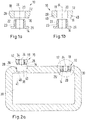
- the assembly 10 comprises a fixing element 12 and an insert 14.
- the fixing element 12 has an outer side 18 and an inner side 16, the inner side 16 being designed to be arranged within a blind hole 36.
- the outer side 18 can accordingly be arranged on an outer surface of a component 30, for example flush.
- a receiving area 20 extends between the outer side 18 and the inner side 16 and is designed to receive the insert 14.
- the receiving area 20 extends along a longitudinal axis 24.
- the insert 14 comprises a contact area 22 which can be arranged in the receiving area 20.
- the contact area 22 extends along the longitudinal axis 24.
- the insert piece 14 further comprises a collar element 26 which is connected to the contact area 22.
- the collar element 26 extends at least partially around the longitudinal axis 24.
- the contact area 22 can furthermore have knurling on its surface. When the contact area 22 is inserted into the receiving area 20, the knurling displaces material and thus creates undercuts between the contact area 22 and the receiving area 20.
- the contact area 22 can have ribs that are formed in a direction parallel to the longitudinal axis 24.
- the contact area 22 can have intersecting ribs which have an angle of 30 ° to 60 °, preferably 45 °, to a direction parallel to the longitudinal axis.
- the contact area can also have a change in diameter along the longitudinal axis that forms undercuts.
- the collar element 26 further has a first diameter that is greater than a second diameter of the receiving area 20. Furthermore, the first diameter is larger than an average diameter of the contact area 22.
- the collar element 26 can therefore be designed as a flange which extends away from the longitudinal axis 24 and the contact area 22.
- the contact area 22 can be plugged into the receiving area 20.
- the insert 14 has a base cylinder 23 extending along the longitudinal axis 24.
- the contact area 22 protrudes from the basic cylinder 23.
- a connection between the contact area 22 and the receiving area 20 is made by embedding the insert 14 in the fixing element 12 by means of ultrasound or alternatively by means of a connection by overmolding the insert 14 with plastic in the injection molding machine. If the fixing element 12 consists of a plastic material, the plastic material of the fixing element 12 is melted on during ultrasonic embedding. The melted plastic material wraps around the contact area 22 and thereby connects the contact area 22 to the receiving area 20. After the plastic material has solidified, the plastic material fixes the contact area 22 in the receiving area 20 and thus the insert 14 in the fixing element 12.
- the contact area 22 can have a third diameter that is greater than or at least equal to the second diameter of the receiving area 20; the contact area 22 will widen the receiving area 20 when it is inserted into the receiving area 20.
- a press connection is established between the contact area 22 and the receiving area 20. After the insertion, the contact area 22 is therefore fixed in the receiving area 20 in this case by the press connection.
- an adhesive connection can be provided between the contact area 22 and the receiving area 20.
- the adhesive connection is designed in such a way that the material of the fixing element 12 is glued to the material of the insert 14.
- the fixing element 12 further comprises a connection area 28 for connection to a component 30.
- Figure 1b shows an example in which the assembly 10 has an energy director 40 on the fixing element 12.
- the energy director 40 is arranged on the connecting area 28.
- the connection area 28 has a larger diameter than on the inside 16.
- the energy director 40 can be arranged, preferably centrally along the longitudinal axis 24, between the outside 18 and the inside 16 and form a transition between the two diameters.
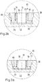
- Figure 2a shows a component 30 with an interior 38.
- the component 30 can be made of a plastic material.
- Two blind holes 36 are formed in a wall of the component 30 on the opposite side to the interior 38.
- the blind holes 36 each have an outer blind hole section 39 and an inner sachlock section 41.
- the outer blind lock section 39 has a fourth diameter.
- the inner sack block section 41 comprises a fifth diameter which is at least as large as the first diameter of the collar element 26.
- the energy director 40 is provided between the outer sack block section 39 and the inner sack block section 41, preferably on a shoulder, the fourth diameter being greater than the fifth diameter.
- the energy director 40 By means of the energy director 40, a melt that forms when the assembly 10 is connected to the blind hole 36 is pressed both into the outer blind hole section 39 and into the inner blind block section 41.
- the energy director 40 forms a material depot for the melt when the assembly 10 is embedded, the blind hole 36.
- the blind hole 36 On the left-hand side, the blind hole 36 is empty and the assembly 10 with the fixing element 12 and the insert 14 has not yet been inserted into the blind hole 36.
- connection area 28 of the fixing element 12 can be connected to the component 30, for example, within a blind hole of the component 30, as in FIG Figure 2a shown on the right.
- shape of the connecting region 28 is adapted to the shape of the blind hole 36 with the outer and inner blind hole sections 39, 41.
- the connecting region 28 thus has an upper section and a lower section which is narrower than the upper section. A step is arranged between the two sections.
- connection area 28 is connected to the outer blind hole section 39 and the inner sachlock section 41 in a materially bonded manner.
- This can be done, for example, by means of ultrasonic embedding or another welding process.
- the material depot which is provided by the energy director 40, is melted in order to generate a plastic melt.
- the plastic melt is pressed between the outer blind hole section 39 and the connecting area 28 or between the inner sachlock section 41 and the connecting area 28. In the process, the plastic melt melts further material both on the outer and inner blind hole sections 39, 41 and on the connection area 28, so that a connection is created.
- the fixing element 12 and the component 30 can consist of a weldable plastic pairing.
- the base polymer of the weldable plastic pairing can be identical, e.g. B. PA66 GF50 with PA66 CF40.
- Figure 2b shows an enlargement of the in Figure 2a Blind holes 36 shown on the right with the subassembly 10 firmly connected therewith. After the plastic melt has solidified, the plastic melt forms a material connection 46 between the outer blind hole section 39 or the inner bag lock section 41 and the first connection area 28.
- the insert 14 is now arranged with its collar element 26 in the blind hole 36 and secured in a form-fitting manner against being torn out along the longitudinal axis 24 in the direction of the outside 18 by the fixing element 12.
- the insert 14 can, for example, have a through opening 34 in order to receive a fastening means over its entire length.
- the through opening 34 can for example be provided with an internal thread 42 so that a screw can be screwed into the insert 14.
- the insert 14 can have a blind hole (not shown).
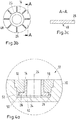
- the Figures 3a and 3c show a schematic view of an assembly 10 with an anti-rotation element which is designed as a plurality of projections 48 which protrude from the collar element 26.
- the basic cylinder 23 can have a smaller diameter than the receiving area 20, so that there is a slight play between the contact area 22 and the receiving area 20.
- the basic cylinder 23 can be designed in such a way that there is a transition fit or a press fit between the receiving region 20 and the transition region 22.
- the projections 48 protrude from a side facing the fixing element 12, the collar element 26, as in FIG Figure 3a shown.
- Figure 3b shows a view of the collar element 26 along the longitudinal axis 24 as seen from the fixing element 12.
- the projections 48 are arranged in a star shape around the longitudinal axis 24, ie they extend in the radial direction away from the longitudinal axis 24 along the collar element 26.
- the projections are in accordance with this Figure 3c , which shows a section along a chord through the collar element 26 according to FIG Figure 3b shows, formed with a sharp edge, so that when connecting the insert 14 to the fixing element 12 or when tightening a Cut, stamp or press the screw in the insert 14 into the material of the fixing element 12. In doing so, they form an anti-twist device.
- the material of the fixing element 12 surrounds the projections 48 in the circumferential direction around the longitudinal axis 24, so that a form fit is created in this direction.
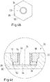
- FIGS. 4a to 4c show a schematic sectional view of an assembly 10 with alternative anti-rotation elements.
- the anti-rotation element has a first securing partner 50 and a second securing partner 52.
- the first securing partner 50 is arranged on the collar element 26 and forms an outer circumference of the collar element 26.
- the first securing partner 50 forms an angular, outer circumference, for example a square or a hexagon, such as in FIG Figure 4b shown.
- the second securing partner 52 is a recess on the fixing element 12 which receives the collar element 26 and is designed to match the first securing partner 50.
- a form fit is provided between the collar element 26 and the fixing element 12, which prevents rotation about the longitudinal axis 24.
- play can also be provided between the basic cylinder 23 and the receiving area 20.
- Figure 4a shows a close uptake of the basic cylinder 23 and play between the collar element 26 or the first securing partner 50 and the second securing partner 52 on the fixing element 18.
- FIG 4c an alternative embodiment is shown.
- the second securing partner 52 is arranged on the blind hole 36 of the component 30.
- the second securing partner 52 picks up the collar element 26 after the assembly 10 has been inserted into the blind hole 36 and secures the insert 14 against rotation about the longitudinal axis 24.
- This figure shows a play between the basic cylinder 23 and the receiving area 20. No play is shown between the first security partner 50 and the second security partner 52. However, it is conceivable that, alternatively or in addition, play is provided between the first securing partner 50 and the second securing partner 52, as long as securing against rotation about the longitudinal axis 24 is guaranteed.
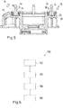
- Figure 5 shows a further embodiment of the component 30, the component 30 being designed as part of an air spring cup.
- the air spring cup is made of a plastic material.
- the insert pieces 14 have threaded bolts 44 in this embodiment, which extend away from the collar element 26 of the insert piece along the longitudinal axis 24.
- the threaded bolts 44 are arranged on the outside 18 of the fixing element 12.
- FIG. 10 shows a flow diagram of a method 100 for producing a component.
- a blind hole is produced in the component.
- the blind hole is produced on an outer surface of the component and has an outer blind hole section with a fourth diameter and an inner blind hole section with a fifth diameter which is at least as large as the first diameter of the collar element.
- the fourth diameter is larger than the fifth diameter.
- a transition area between the fourth and fifth diameter is designed to accommodate an energy director.
- a further step 104 the assembly is manufactured.
- a contact area of the insert is guided into the receiving area of the fixing element.
- the collar element is arranged on an inside of the fixing element. The inside is defined as the side which is arranged in the blind hole after the assembly has been inserted into the blind hole.
- the collar element then forms a form fit with the fixing element along the longitudinal axis.
- the first diameter of the collar element is larger than the second diameter of the receiving area.
- the contact area and the receiving area are connected to one another. This can be done, for example, by means of ultrasonic embedding or another welding process. Alternatively or additionally, an adhesive connection can be provided between the contact area and the receiving area. As an alternative or in addition, the contact area has a larger diameter than the receiving area, so that the contact area can be pressed into the receiving area in order to be fixed therein.
- the insert piece can be encapsulated by means of plastic injection molding, the plastic forming the fixing element.
- the fixing element and insert are connected to one another in a non-positive and / or positive manner.
- the frictional connection is created by the fact that the plastic is shrunk onto the metal, since the plastic has a greater coefficient of thermal expansion than the metallic insert.
- the assembly is inserted into the blind hole.
- the inside is arranged inside the blind hole.
- the outside of the fixing element points away from the blind hole.
- the collar element is arranged inside the blind hole.
- a melt is generated by means of an energy director arranged between the outer blind hole section with a fourth diameter and the inner blind hole section with the fifth diameter, which by a pressure that presses the assembly into the component, between the connecting section and the outer blind hole section or the inner Blind hole section is pressed.
- the fourth diameter is larger than the fifth diameter.
Landscapes
- Engineering & Computer Science (AREA)
- Mechanical Engineering (AREA)
- General Engineering & Computer Science (AREA)
- Connection Of Plates (AREA)
- Standing Axle, Rod, Or Tube Structures Coupled By Welding, Adhesion, Or Deposition (AREA)
Applications Claiming Priority (1)
| Application Number | Priority Date | Filing Date | Title |
|---|---|---|---|
| DE102020103835.6A DE102020103835A1 (de) | 2020-02-13 | 2020-02-13 | Baugruppe umfassend ein Fixierelement und ein Einsatzstück und Verfahren zum Herstellen eines Bauteils mit der Baugruppe |
Publications (1)
| Publication Number | Publication Date |
|---|---|
| EP3865719A1 true EP3865719A1 (fr) | 2021-08-18 |
Family
ID=74184341
Family Applications (1)
| Application Number | Title | Priority Date | Filing Date |
|---|---|---|---|
| EP20210583.9A Withdrawn EP3865719A1 (fr) | 2020-02-13 | 2020-11-30 | Unité comprenant un élément de fixation et une pièce d'insert et procédé de fabrication d'un élément pourvu de l'unité |
Country Status (2)
| Country | Link |
|---|---|
| EP (1) | EP3865719A1 (fr) |
| DE (1) | DE102020103835A1 (fr) |
Citations (8)
| Publication number | Priority date | Publication date | Assignee | Title |
|---|---|---|---|---|
| US3547741A (en) * | 1966-02-25 | 1970-12-15 | Uniroyal Inc | Friction welding tool |
| GB1453190A (en) * | 1972-12-11 | 1976-10-20 | Crawley Mouldings Ltd | Method of securing inserts into plastics bodies |
| US4846612A (en) * | 1987-10-19 | 1989-07-11 | Shur-Lok Corporation | Sandwich panel fastener |
| DE3831308C1 (fr) | 1988-09-15 | 1990-01-18 | Dr.Ing.H.C. F. Porsche Ag, 7000 Stuttgart, De | |
| AT11594U1 (de) * | 2009-10-02 | 2011-01-15 | Maag Automotive Gmbh | Einsatz für aus einem verbundwerkstoff aufgebaute sportgeräte |
| DE102013202583B3 (de) * | 2013-02-18 | 2014-07-03 | Böllhoff Verbindungstechnik GmbH | Reibschweißelement, Gehäuse und Verbindungsverfahren für das Reibschweißelement mit einem Gehäuse |
| DE102016211442A1 (de) * | 2016-06-27 | 2017-12-28 | Bayerische Motoren Werke Aktiengesellschaft | Verfahren zum Herstellen eines Fahrzeugbauteils und Fahrzeugbauteil |
| WO2018135996A1 (fr) * | 2017-01-19 | 2018-07-26 | Ikea Supply Ag | Procédé d'ancrage d'élément raccord, machine permettant la mise en œuvre dudit procédé et kit d'ancrage d'élément raccord |
-
2020
- 2020-02-13 DE DE102020103835.6A patent/DE102020103835A1/de active Pending
- 2020-11-30 EP EP20210583.9A patent/EP3865719A1/fr not_active Withdrawn
Patent Citations (8)
| Publication number | Priority date | Publication date | Assignee | Title |
|---|---|---|---|---|
| US3547741A (en) * | 1966-02-25 | 1970-12-15 | Uniroyal Inc | Friction welding tool |
| GB1453190A (en) * | 1972-12-11 | 1976-10-20 | Crawley Mouldings Ltd | Method of securing inserts into plastics bodies |
| US4846612A (en) * | 1987-10-19 | 1989-07-11 | Shur-Lok Corporation | Sandwich panel fastener |
| DE3831308C1 (fr) | 1988-09-15 | 1990-01-18 | Dr.Ing.H.C. F. Porsche Ag, 7000 Stuttgart, De | |
| AT11594U1 (de) * | 2009-10-02 | 2011-01-15 | Maag Automotive Gmbh | Einsatz für aus einem verbundwerkstoff aufgebaute sportgeräte |
| DE102013202583B3 (de) * | 2013-02-18 | 2014-07-03 | Böllhoff Verbindungstechnik GmbH | Reibschweißelement, Gehäuse und Verbindungsverfahren für das Reibschweißelement mit einem Gehäuse |
| DE102016211442A1 (de) * | 2016-06-27 | 2017-12-28 | Bayerische Motoren Werke Aktiengesellschaft | Verfahren zum Herstellen eines Fahrzeugbauteils und Fahrzeugbauteil |
| WO2018135996A1 (fr) * | 2017-01-19 | 2018-07-26 | Ikea Supply Ag | Procédé d'ancrage d'élément raccord, machine permettant la mise en œuvre dudit procédé et kit d'ancrage d'élément raccord |
Also Published As
| Publication number | Publication date |
|---|---|
| DE102020103835A1 (de) | 2021-08-19 |
Similar Documents
| Publication | Publication Date | Title |
|---|---|---|
| DE102008029236B3 (de) | Verbindungselement mit einer Schraube und einer daran unverlierbar angeordneten Hülse | |
| WO2014124841A1 (fr) | Élément de soudage par friction et procédé de liaison de cet élément de soudage par friction à un boîtier | |
| EP2268472A1 (fr) | Procédé de fabrication d'une pièce moulée dotée d'une section transversale annulaire et pièce moulée fabriquée selon un procédé de ce type | |
| DE102010010651A1 (de) | Schraubteil | |
| EP2184525A1 (fr) | Raccordement de tuyau avec un tuyau et procédé de fabrication d'une section de raccordement d'un raccordement de tuyau | |
| WO2019149695A1 (fr) | Composant comprenant une fonction de compensation de tolérance | |
| EP3042090A1 (fr) | Insert d'assemblage ainsi que procédé d'inclusion et procédé de fabrication correspondant | |
| DE3838935A1 (de) | Kupplungsstueck | |
| EP2857699A1 (fr) | Douille taraudée à visser | |
| DE19755020A1 (de) | Axialgelenk | |
| DE102014014296A1 (de) | Hohlprofilbauteil aus einem faserverstärkten thermoplastischen Kunststoff | |
| EP4264065B1 (fr) | Pièce de vis à section transversale annulaire | |
| EP0534001A1 (fr) | Assemblage à vis pour assembler deux pièces de construction, qui ont vue distance, notamment des plaques de métal | |
| EP3894711B1 (fr) | Cheville à expansion | |
| DE10334898B4 (de) | Halteelement zur Fixierung wenigstens eines Lagers | |
| DE102011109130A1 (de) | Flansch, Verbindungsanordnung und Verfahren zur axialen Anbindung eines Zug- und/oder Druckstabes | |
| DE102011011215B4 (de) | Verfahren zum Verbinden und Verbindung eines ersten Werkstückes mit einem zweiten Werkstück | |
| DE10020218B4 (de) | Montageeinheit aus einem Bauteil und mindestens einer gewindeformenden Schraube | |
| DE10322595B4 (de) | Kolbenpumpe, sowie Verfahren zu ihrer Herstellung | |
| EP3865719A1 (fr) | Unité comprenant un élément de fixation et une pièce d'insert et procédé de fabrication d'un élément pourvu de l'unité | |
| EP2143178A1 (fr) | Dispositif d'accouplement de boîtier hf et procédé de fabrication dudit dispositif | |
| DE102009032083A1 (de) | Verfahren zum Einpressen eines hülsenförmigen Einpresselements in eine Fügeöffnung eines Bauteils | |
| DE102018102934A1 (de) | Axialkugelzapfen | |
| DE102004010603B4 (de) | Klemmvorrichtung | |
| EP4040927A1 (fr) | Module comprenant une platine et une partie de base |
Legal Events
| Date | Code | Title | Description |
|---|---|---|---|
| PUAI | Public reference made under article 153(3) epc to a published international application that has entered the european phase |
Free format text: ORIGINAL CODE: 0009012 |
|
| STAA | Information on the status of an ep patent application or granted ep patent |
Free format text: STATUS: THE APPLICATION HAS BEEN PUBLISHED |
|
| AK | Designated contracting states |
Kind code of ref document: A1 Designated state(s): AL AT BE BG CH CY CZ DE DK EE ES FI FR GB GR HR HU IE IS IT LI LT LU LV MC MK MT NL NO PL PT RO RS SE SI SK SM TR |
|
| STAA | Information on the status of an ep patent application or granted ep patent |
Free format text: STATUS: THE APPLICATION IS DEEMED TO BE WITHDRAWN |
|
| 18D | Application deemed to be withdrawn |
Effective date: 20220219 |