EP2006470A2 - Mécanisme d'entraînement pour un revêtement de piscine - Google Patents
Mécanisme d'entraînement pour un revêtement de piscine Download PDFInfo
- Publication number
- EP2006470A2 EP2006470A2 EP20080450092 EP08450092A EP2006470A2 EP 2006470 A2 EP2006470 A2 EP 2006470A2 EP 20080450092 EP20080450092 EP 20080450092 EP 08450092 A EP08450092 A EP 08450092A EP 2006470 A2 EP2006470 A2 EP 2006470A2
- Authority
- EP
- European Patent Office
- Prior art keywords
- drive
- locking element
- drive according
- shaft
- motor
- Prior art date
- Legal status (The legal status is an assumption and is not a legal conclusion. Google has not performed a legal analysis and makes no representation as to the accuracy of the status listed.)
- Withdrawn
Links
- 230000009182 swimming Effects 0.000 title claims abstract description 15
- 238000000034 method Methods 0.000 claims abstract description 6
- 238000004146 energy storage Methods 0.000 claims description 12
- 230000005611 electricity Effects 0.000 claims description 2
- 230000007257 malfunction Effects 0.000 description 2
- 238000004519 manufacturing process Methods 0.000 description 2
- 241001465754 Metazoa Species 0.000 description 1
- 238000013459 approach Methods 0.000 description 1
- 238000011109 contamination Methods 0.000 description 1
- 230000001419 dependent effect Effects 0.000 description 1
- 238000013461 design Methods 0.000 description 1
- 238000011161 development Methods 0.000 description 1
- 238000006073 displacement reaction Methods 0.000 description 1
- 238000003780 insertion Methods 0.000 description 1
- 230000037431 insertion Effects 0.000 description 1
- 238000005259 measurement Methods 0.000 description 1
- 230000003287 optical effect Effects 0.000 description 1
- 230000001681 protective effect Effects 0.000 description 1
Images
Classifications
-
- E—FIXED CONSTRUCTIONS
- E04—BUILDING
- E04H—BUILDINGS OR LIKE STRUCTURES FOR PARTICULAR PURPOSES; SWIMMING OR SPLASH BATHS OR POOLS; MASTS; FENCING; TENTS OR CANOPIES, IN GENERAL
- E04H4/00—Swimming or splash baths or pools
- E04H4/06—Safety devices; Coverings for baths
- E04H4/08—Coverings consisting of rigid elements, e.g. coverings composed of separate or connected elements
- E04H4/082—Coverings consisting of rigid elements, e.g. coverings composed of separate or connected elements composed of flexibly or hingedly-connected slat-like elements, which may or may not be wound-up on a fixed axis
-
- E—FIXED CONSTRUCTIONS
- E04—BUILDING
- E04H—BUILDINGS OR LIKE STRUCTURES FOR PARTICULAR PURPOSES; SWIMMING OR SPLASH BATHS OR POOLS; MASTS; FENCING; TENTS OR CANOPIES, IN GENERAL
- E04H4/00—Swimming or splash baths or pools
- E04H4/06—Safety devices; Coverings for baths
- E04H4/10—Coverings of flexible material
- E04H4/101—Coverings of flexible material wound-up on a fixed axis
Definitions
- the invention relates to a drive of an element of a swimming pool cover, which is slidable on rails along a swimming pool, with a drive wheel, a motor for driving the drive wheel and a controller for the motor.
- the invention further relates to a method for opening and / or closing an element of a swimming pool cover in which the element with a drive wheel, which is driven by an electric motor, is displaced on rails along a swimming pool.
- Pool covers of the type involved here usually consist of at least two, but usually more elements, which can be moved to arranged next to the pool rails and telescoped into each other, so that a large part of the swimming pool is no longer covered by the pool cover.
- swimming pool covers in which all elements in the pushed together state can be pushed completely out of the pool area.
- swimming pool cover If such a swimming pool cover is electrically driven to open and close, it must be ensured that the elements of the pool cover can not be moved in the non-functioning state of the drive. This is particularly important in the closed state of the pool cover so that the pool cover is not unintentionally, for example, by wind or by small children opened, and then objects, animals or children can fall into the pool.
- the invention is therefore based on the object to remedy this situation.
- a simple but reliable embodiment of the invention is characterized in that an electromagnet is provided for driving the locking element. Since it is preferred in the invention that the locking element is pressed by the force of a spring in the locking position and moved by its drive in the unlocked position, both functions can be met in a simple manner by a one-sided spring-loaded solenoid.
- the locking element when the locking element is pivotable about a shaft.
- one of a preferred embodiment of the invention is provided with a mechanically connected to the locking element attack point for a release tool.
- the point of application can be formed by a 3-, 4- or 6-Kant, to which a correspondingly shaped tool, a so-called 3-, 4- or 6-wrench can be applied , with the help of which the shaft can be twisted and thus the locking element can be unlocked.
- the locking element is a lever which can be pivoted about the shaft.
- the engagement area can be set very easily by changing the setting angle of the lever.
- two spaced-apart levers can be arranged on the shaft. This is preferred for the reason that then in each case a locking element, namely that which is closest to the respective end of the rail, can be used to lock the drive to the rail, so that the corresponding recesses or other locking parts on the rail are arranged, as far as possible at the end of the rail can be mounted. It is understood that the last-mentioned advantage also comes into play, if two differently designed locking elements are used, which also must not be pivotable on a shaft, but can be pivoted or moved in other ways.
- the invention can be improved by the Shaft is slidable in the direction of its axis of rotation against the force of a spring. In this way, too tight a concern of the locking element is avoided on the corresponding locking parts on the rail, which on the one hand helps to avoid damage, and on the other hand prevents excessive jamming.
- the method according to the invention may be characterized in that an electrically actuable locking element which cooperates with a locking device on a rail, is moved into and out of its operative position that both the motor and the locking element driven by a common control and that the motor is briefly and / or repeatedly driven in one and / or other direction before and / or during actuation of the locking element.
- an electrical energy store is arranged on the drive for the power supply of the electrically actuatable locking element.
- This energy storage can be a conventional battery or a rechargeable battery.
- the Drive has a housing, the solar cells are arranged within the housing and the housing in the solar cells is transparent, then not only a visually appealing but also the solar cells protective design of the drive can be realized.
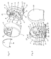
- a mounting plate 3 is accommodated on which all the essential parts of Drive are attached.
- a shaft 4 is arranged, which leads through an opening in the mounting plate 3 to a holder 5 on the back of the mounting plate 3.
- an electrical energy storage device for example, a battery or a battery is inserted via which a part or all electrical components such as a drive motor 6 and the control electronics, not shown, of the drive are supplied with electrical energy.
- a plate 7 is fixed to the mounting plate 3, to which four switches 8 to 11 and a row of LED lamps 12 are arranged.
- the switch 8 is a main switch for switching on and off the drive, the switch 9 is used to specify the left-right run of the drive, the switch 10 is a reset switch to the travel of the drive To reprogram the driven element of the swimming pool cover, and the switch 11 is free and can be assigned with additional programmable functions.
- the LED lamps 12 indicate the state of charge of the electrical energy storage.
- an opening 12 is attached to the front of the housing 1 and next to it a further opening 13, through which the switches 8 to 11 accessible and the LED lamps 12 are visible.
- the openings 12 and 13 are closed with the housing cover 2a.
- a drive wheel 16 is driven via a gear 14 and a shaft 15, which engages on a rail, not shown in the drawing, on which the elements of the swimming pool cover are slidable over rollers.
- the drive motor 6 together with gear 14, shaft 15 and drive wheel 16 as a structural unit or module 17 executed, which is displaceable in a recess 37 in the mounting plate 3 in the direction of the double arrow 19 against the force of a spring, not shown.
- the drive according to the invention characterized in that the module 17 via a push rod 18 in the central region of a bar 19th supported, which is pivotally mounted at one end 20.
- an adjusting screw 22 is mounted, via which the beam 19 is supported on a dial 23.
- the dial 23 is mounted eccentrically or has adjustment surfaces 25, 26, which have different sizes of the rotation axis 24.
- Level setting surfaces 25, 26, the number of which be arbitrarily large in the context of spatial conditions can, have the advantage that an unintentional rotation of the dial 23 under load, that is, when the adjustment screw 22 is pressed by the wheel 16 against a setting surface, can be easily avoided, since the force vector passes through the axis of rotation 24 of the dial 23.
- a round dial 23 is conceivable, which is mounted eccentrically. The dial 23 is clamped firmly after setting.
- a mounting bar 27 is provided, which can be attached to one of two mounting brackets 28 or 29.
- the mounting brackets 28 and 29 are in turn attached to the mounting plate 3.
- the two mounting brackets 28 and 29 are provided to allow the possibility of being able to fix the drive according to the invention both on the left and on the right side of an element of the pool cover.
- only the mounting bar 27 must be attached to the respective mounting bracket 28 or 29 and the switch 9 are switched to the corresponding position for left or right-handed rotation.
- a measuring wheel any other measuring device can be used with which the path and / or the speed with which the drive according to the invention moves relative to the rail can be detected.
- the module 17 thus forms a common carrier for the counting wheel 30 and the drive wheel 16. A separate storage would also be possible.
- the counting wheel 30 or the sensors detecting the rotation of the counting wheel are connected via a control line (not shown in the drawing) to the control (not shown) for the drive motor 6.
- the counting wheel 30 constantly knows the current position of the drive, this information can be used to reduce or increase the motor drive speed continuously or stepwise during startup and deceleration of the drive in the region of the end positions of the driven element of the swimming pool cover. Furthermore, by the counting wheel 30th the safety in the operation of the drive can be increased because the speed specifications can be compared by the control of the drive with the actual, measurable by the counter 30 speed. If an obstacle, for example a body part of a person or another object, is located in the guideway and also hampers the displacement of the element only slightly, the actual travel speed is reduced compared to the setpoint speed so that the drive is stopped immediately and, if necessary, a return movement is initiated can. Additionally or alternatively, a disability can also be detected by a motor current measurement.
- an obstacle for example a body part of a person or another object
- levers 32 and 33 which serve to set the drive and thus the driven element of the pool cover in the end positions.
- corresponding locking devices such as depressions or obstacles of other types are attached, for example by recesses in the rails or by attaching one or more elevations on the rails, in or on which the levers 32, 33 can attack.
- the levers 32, 33 are driven via the shaft 31 by an electric drive 34, for example a lifting magnet, which is connected to the shaft 31 via a linkage.
- the electric drive 34 of the shaft 31 is also powered by the electrical energy storage.
- This drive 34 for the levers 32, 33 is designed so that the levers 32, 33, preferably by a spring, constantly in the underlying (in Fig. 1 and 2 is the upper position shown) locking position are pressed when the drive is out of action. This is a safety issue, since the pool cover can not inadvertently be opened by children, for example, when the drive is inoperative.
- the use of two locking elements 32 and 33 is therefore preferred, because then each one locking element 32 and 33, namely that which is closest to the respective end of the rail, can be used to lock the drive to the rail, so that the corresponding recesses or other locking parts which are arranged on the rail, as far as possible on End of the rail can be attached. The spaced in the respective end position from the end of the rail locking element 32 and 33 is then always inoperative. Of course, only a single locking element 32 or 33 can be used.
- the controller can control the motor 6 so that this briefly or once in multiple travels in one and / or other direction, so that the clamping force dissolved or loosened and the levers 32 and 33 can be unlocked.
- the shaft 31 in the axial direction in both directions against the force of springs can be slightly displaced, which on the one hand reduces the clamping forces and on the other hand reduces the risk of damage to the drive and / or the devices on the rail by jerky opening and / or closing.
- solar cells may be provided which charge the energy storage.
- a voltage monitor of the energy storage the charging process terminate when a target voltage is reached.
- the solar cells can be attached to almost anywhere on the drive or on the element of the pool cover. However, in the context of the invention, it is preferred if these are mounted on or within the housing 1 of the drive. It is preferred if the solar cells are mounted on panels, not shown, which are fastened within the housing 1 in the region of chamfers 35 and 36 at the upper edge of the mounting plate 3. In this case, the housing 1 must be translucent, at least in the area of the solar cells, but offers good protection against damage and / or contamination of the solar cells.
Landscapes
- Engineering & Computer Science (AREA)
- Architecture (AREA)
- Civil Engineering (AREA)
- Structural Engineering (AREA)
- Toys (AREA)
- Power-Operated Mechanisms For Wings (AREA)
Applications Claiming Priority (1)
| Application Number | Priority Date | Filing Date | Title |
|---|---|---|---|
| AT9752007A AT505423B1 (de) | 2007-06-21 | 2007-06-21 | Antrieb für eine schwimmbadabdeckung |
Publications (1)
| Publication Number | Publication Date |
|---|---|
| EP2006470A2 true EP2006470A2 (fr) | 2008-12-24 |
Family
ID=39708824
Family Applications (1)
| Application Number | Title | Priority Date | Filing Date |
|---|---|---|---|
| EP20080450092 Withdrawn EP2006470A2 (fr) | 2007-06-21 | 2008-06-23 | Mécanisme d'entraînement pour un revêtement de piscine |
Country Status (2)
| Country | Link |
|---|---|
| EP (1) | EP2006470A2 (fr) |
| AT (1) | AT505423B1 (fr) |
Family Cites Families (2)
| Publication number | Priority date | Publication date | Assignee | Title |
|---|---|---|---|---|
| DE7921794U1 (de) * | 1979-07-31 | 1980-01-03 | Deutsche Mcgregor Gmbh, 2800 Bremen | Rollhalle fuer schwimmbaeder |
| FR2738584B1 (fr) * | 1995-09-11 | 1998-04-03 | Charbonnel Paul | Abri de protection amovible d'une aire d'activite ou de loisir |
-
2007
- 2007-06-21 AT AT9752007A patent/AT505423B1/de not_active IP Right Cessation
-
2008
- 2008-06-23 EP EP20080450092 patent/EP2006470A2/fr not_active Withdrawn
Also Published As
| Publication number | Publication date |
|---|---|
| AT505423B1 (de) | 2009-03-15 |
| AT505423A1 (de) | 2009-01-15 |
Similar Documents
| Publication | Publication Date | Title |
|---|---|---|
| EP2293392B1 (fr) | Dispositif et procédé de verrouillage d'un connecteur dans une prise | |
| EP2910321B1 (fr) | Appareil de pose de rivets aveugles | |
| EP2648935B1 (fr) | Dispositif de charge avec détection de verrouillage | |
| DE3709688A1 (de) | Automatische tuer mit automatischem verriegelungssystem | |
| WO2020212064A1 (fr) | Dispositif de fermeture pour une porte de véhicule d'un véhicule automobile | |
| WO2017041790A1 (fr) | Dispositif de prise d'une poignée de porte d'un véhicule automobile | |
| EP3243984A1 (fr) | Dispositif de verrou de porte pour une porte anti-panique | |
| EP3543439B1 (fr) | Procédé pour un ensemble serrure | |
| DE102009001851B4 (de) | Kraftfahrzeug mit Notverriegelungseinrichtungen mit Schaltnüssen für mechanische Aussenverriegelungen | |
| DE102015108739A1 (de) | Verfahren zur Steuerung eines Kraftfahrzeugtürverschlusses | |
| DE102013105429B4 (de) | Elektrische Lenkradschlosseinrichtung | |
| DE3218112C2 (de) | Verschlußeinrichtung | |
| DE102014104128B4 (de) | Zuhaltung | |
| EP2381055B1 (fr) | Serrure pour un élément de fermeture | |
| DE19916733A1 (de) | Schließanlage für Fahrzeuge | |
| EP2486207A1 (fr) | Dispositif de déverrouillage | |
| DE102013212508B4 (de) | Türanlage | |
| AT505423B1 (de) | Antrieb für eine schwimmbadabdeckung | |
| EP2605257B1 (fr) | Entraînement par moteur pour un disjoncteur | |
| DE102013212514B4 (de) | Türanlage mit einer Verriegelungseinrichtung zur Verriegelung eines Türflügels | |
| AT10530U1 (de) | Antrieb für eine schwimmbadabdeckung | |
| DE69803021T2 (de) | Motorbetriebene Verriegelungsvorrichtung eines Türflügels, Tür mit solch einer Vorrichtung und damit ausgerüstetes Schienenfahrzeug | |
| EP4238798A2 (fr) | Unité multifonction pour un hayon de véhicule, ensemble de hayon et procédé d'actionnement de l'unité multifonction | |
| WO2016150431A1 (fr) | Dispositif d'actionnement électrique avec alimentation électrique de secours pour une serrure électrique de véhicule à moteur et procédé associé | |
| DE102007031144A1 (de) | Torantrieb |
Legal Events
| Date | Code | Title | Description |
|---|---|---|---|
| PUAI | Public reference made under article 153(3) epc to a published international application that has entered the european phase |
Free format text: ORIGINAL CODE: 0009012 |
|
| AK | Designated contracting states |
Kind code of ref document: A2 Designated state(s): AT BE BG CH CY CZ DE DK EE ES FI FR GB GR HR HU IE IS IT LI LT LU LV MC MT NL NO PL PT RO SE SI SK TR |
|
| AX | Request for extension of the european patent |
Extension state: AL BA MK RS |
|
| STAA | Information on the status of an ep patent application or granted ep patent |
Free format text: STATUS: THE APPLICATION IS DEEMED TO BE WITHDRAWN |
|
| 18D | Application deemed to be withdrawn |
Effective date: 20120103 |