EP2006582A2 - Dichtungsstruktur für eine kühlbehandlungsvorrichtung oder eine mehrkammer-wärmbehandlungsvorrichtung, und für die dichtungsstruktur druckregelverfahren und betriebsverfahren - Google Patents
Dichtungsstruktur für eine kühlbehandlungsvorrichtung oder eine mehrkammer-wärmbehandlungsvorrichtung, und für die dichtungsstruktur druckregelverfahren und betriebsverfahren Download PDFInfo
- Publication number
- EP2006582A2 EP2006582A2 EP06731307A EP06731307A EP2006582A2 EP 2006582 A2 EP2006582 A2 EP 2006582A2 EP 06731307 A EP06731307 A EP 06731307A EP 06731307 A EP06731307 A EP 06731307A EP 2006582 A2 EP2006582 A2 EP 2006582A2
- Authority
- EP
- European Patent Office
- Prior art keywords
- pressure
- grease
- seal structure
- cooling
- chamber
- Prior art date
- Legal status (The legal status is an assumption and is not a legal conclusion. Google has not performed a legal analysis and makes no representation as to the accuracy of the status listed.)
- Granted
Links
Images

Classifications
-
- F—MECHANICAL ENGINEERING; LIGHTING; HEATING; WEAPONS; BLASTING
- F16—ENGINEERING ELEMENTS AND UNITS; GENERAL MEASURES FOR PRODUCING AND MAINTAINING EFFECTIVE FUNCTIONING OF MACHINES OR INSTALLATIONS; THERMAL INSULATION IN GENERAL
- F16J—PISTONS; CYLINDERS; SEALINGS
- F16J15/00—Sealings
- F16J15/16—Sealings between relatively-moving surfaces
- F16J15/40—Sealings between relatively-moving surfaces by means of fluid
- F16J15/406—Sealings between relatively-moving surfaces by means of fluid by at least one pump
-
- F—MECHANICAL ENGINEERING; LIGHTING; HEATING; WEAPONS; BLASTING
- F27—FURNACES; KILNS; OVENS; RETORTS
- F27B—FURNACES, KILNS, OVENS OR RETORTS IN GENERAL; OPEN SINTERING OR LIKE APPARATUS
- F27B17/00—Furnaces of a kind not covered by any of groups F27B1/00 - F27B15/00
- F27B17/0016—Chamber type furnaces
-
- F—MECHANICAL ENGINEERING; LIGHTING; HEATING; WEAPONS; BLASTING
- F27—FURNACES; KILNS; OVENS; RETORTS
- F27D—DETAILS OR ACCESSORIES OF FURNACES, KILNS, OVENS OR RETORTS, IN SO FAR AS THEY ARE OF KINDS OCCURRING IN MORE THAN ONE KIND OF FURNACE
- F27D7/00—Forming, maintaining or circulating atmospheres in heating chambers
- F27D7/06—Forming or maintaining special atmospheres or vacuum within heating chambers
-
- F—MECHANICAL ENGINEERING; LIGHTING; HEATING; WEAPONS; BLASTING
- F27—FURNACES; KILNS; OVENS; RETORTS
- F27D—DETAILS OR ACCESSORIES OF FURNACES, KILNS, OVENS OR RETORTS, IN SO FAR AS THEY ARE OF KINDS OCCURRING IN MORE THAN ONE KIND OF FURNACE
- F27D9/00—Cooling of furnaces or of charges therein
-
- F—MECHANICAL ENGINEERING; LIGHTING; HEATING; WEAPONS; BLASTING
- F27—FURNACES; KILNS; OVENS; RETORTS
- F27D—DETAILS OR ACCESSORIES OF FURNACES, KILNS, OVENS OR RETORTS, IN SO FAR AS THEY ARE OF KINDS OCCURRING IN MORE THAN ONE KIND OF FURNACE
- F27D99/00—Subject matter not provided for in other groups of this subclass
- F27D99/0073—Seals
-
- Y—GENERAL TAGGING OF NEW TECHNOLOGICAL DEVELOPMENTS; GENERAL TAGGING OF CROSS-SECTIONAL TECHNOLOGIES SPANNING OVER SEVERAL SECTIONS OF THE IPC; TECHNICAL SUBJECTS COVERED BY FORMER USPC CROSS-REFERENCE ART COLLECTIONS [XRACs] AND DIGESTS
- Y10—TECHNICAL SUBJECTS COVERED BY FORMER USPC
- Y10T—TECHNICAL SUBJECTS COVERED BY FORMER US CLASSIFICATION
- Y10T137/00—Fluid handling
- Y10T137/0318—Processes
- Y10T137/0396—Involving pressure control
Definitions
- the present invention relates to a seal structure, a cooling treatment apparatus, a multi-chamber heat treatment apparatus, a pressure regulating method, and an operating method.
- a heat treating apparatus that performs so-called tempering by heating and cooling a metal member that is a treatment object conventionally performs cooling treatment by placing the treatment object that has been heat treated midway in a flow path of a cooling gas that circulates in a heat treating furnace.
- the treatment object is placed in a cooling chamber that is formed within the heat treating furnace, and by supplying a coolant gas to this cooling chamber and rotating a fan, the coolant gas is circulated (refer to Patent Document 1).
- the cooling chamber is constituted by a pressurized container.
- the motor that rotates the fan is arranged inside of the pressurized container that serves as the cooling chamber.
- a motor that can be used inside of a pressurized container is costly due to its special features, so using a moderately priced general-purpose motor has been desired.
- a general-purpose motor in order to transmit the rotation of the general-purpose motor that is arranged outside of the pressurized container, it is necessary to pass the output shaft of the general-purpose motor or the rotating shaft that is connected thereto through the container wall of the pressurized container and arrange a shaft seal structure between the output shaft or rotating shaft and the container wall.
- a magnetic seal for example, has been proposed as the shaft seal structure that can be used in the container wall of the pressurized container.
- the present invention was achieved in view of the above circumstances, and has as its object to provide a shaft seal structure that is capable of being suitably applied to a rotating shaft that passes through a container wall of a pressurized container, a cooling treatment apparatus that is provided with this shaft seal structure, a multi-chamber heat treatment apparatus, a pressure regulating method, and an operating method.
- the shaft seal structure according to the present invention is characterized by providing at a fitting portion between a container wall of a pressurized container in which high pressure gas is enclosed and a rotating shaft that passes through the container wall O-rings that are disposed at at least two locations in the axial direction of the rotating shaft; and grease that is pressurized to approximately the same pressure as the pressure of the high pressure gas in a space that is formed by the rotating shaft, the container wall, and the O-rings.
- a grease pressure measuring portion that measures changes in the pressure of the grease that is filled in the space
- a gas leakage detecting portion that detects leaks of the high pressure gas from the pressurized container based on the measurement result of the grease pressure measuring portion.
- a cooling treatment apparatus that disposes a treatment object that has been subjected to heat treatment in a pressurized container and cools the treatment object by supplying high pressure gas in the pressurized container and circulating it with a fan, characterized by providing, at a fitting portion between a rotating shaft that passes through the container wall of the pressurized container to transmit torque to the fan and the container wall, a shaft seal structure comprising O-rings that are disposed at least two locations in the axial direction of the rotating shaft; and grease that is pressurized to approximately the same pressure as the pressure of the high pressure gas in a space that is formed by the rotating shaft, the container wall, and the O-rings.
- the shaft seal structure having a grease pressure measuring portion that measures changes in the pressure of the grease that is filled in the space, and a gas leakage detecting portion that detects leaks of the high pressure gas from the pressurized container based on the measurement result of the grease pressure measuring portion.
- a multi-chamber heat-treatment apparatus that has a heating chamber that performs heat treatment on a treatment object and a cooling chamber that performs cooling treatment on the treatment object that has been subjected to heat treatment in the heating chamber, characterized by using the abovementioned cooling treatment apparatus as the cooling chamber.
- a pressure regulating method is characterized by, in the abovementioned shaft seal structure, pressurizing the grease to a first set pressure and maintaining that state, and pressurizing the grease to the first set pressure again when the pressure of the grease has fallen to a second set pressure.
- An operating method is characterized by, in the abovementioned cooling treatment apparatus, pressurizing the grease to a first set pressure and maintaining that state, and stopping the cooling treatment operation when the pressure of the grease has fallen from a second set pressure to a third set pressure in a predetermined time.
- the shaft seal structure With the shaft seal structure according to the present invention, it is possible to apply a shaft seal structure whose structure is simple and moderately priced and having high reliability to a rotating shaft that passes through the container wall of a pressurized container. Also, since changes in the filling pressure of the grease that is filled at a predetermined pressure between the plurality of O-rings that constitute the shaft seal structure are detected, it is possible to detect that the sealed state by the shaft seal structure has become unmaintainable.
- the cooling treatment apparatus since a shaft seal structure whose structure is simple and moderately priced and having high reliability is applied to a rotation shaft that transmits rotation to a fan that is disposed in the cooling container and passes through the container wall of a pressurized container, it is possible to use a moderately priced general-purpose motor as the motor for driving the rotating shaft. Also, it is possible to detect that the sealed state by the shaft seal structure that is applied to the rotation shaft has become unmaintainable. Also, it is possible to rotate the fan at the desired rotational frequency even when the predetermined rotational frequency of the rotating shaft is low.
- the multi-chamber heat-treatment apparatus With the multi-chamber heat-treatment apparatus according to the present invention, it is possible to reliably perform cooling treatment of a treatment object X and possible to obtain a moderately priced apparatus.
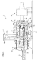
- FIG 1 is a schematic cross-sectional view of the overall structure of a multi-chamber heat treatment apparatus 1 according to the present embodiment.
- the multi-chamber heat treatment apparatus 1 is a multi-chamber-type heat treatment apparatus that is provided with a cooling chamber 2 that cools a treatment object X and a heating chamber 3 that heats the treatment object X, and additionally has an intermediate chamber 4 that is arranged between the cooling chamber 2 and the heating chamber 3.
- the cooling chamber 2 is set to have an approximately cylindrical shape, and is set so that the central axis of this cylindrical shape is horizontally oriented.
- a clutch-type door 5 that moves horizontally in the axial direction of the cooling chamber 2 is provided on one side of the cooling chamber 2 (the right side in FIG 1 ), and a clamp-type vacuum-shield door 6 that opens and closes vertically is provided on the other side (the left side in FIG 1 ).
- a cooling treatment apparatus 2a the entity that includes the cooling chamber 2 and a cooling fan motor 20 and the like described below is called a cooling treatment apparatus 2a.
- the inside space of the multi-chamber heat treatment apparatus 1 enters a sealed state of being shut off from the outside in the state of the door 5 being closed.
- a wind path chamber 7 with a substantially parallelepiped shape that is long in the central axis direction of the cooling chamber 2 is installed inside of this cooling chamber 2, and gas flow guide plates 8a, 8b that adjust the flow path direction of the coolant gas in the cooling chamber 2 are respectively provided at the top and bottom of the wind path chamber 7.
- the interior of the cooling chamber 2 outside of the wind path chamber 7 is vertically divided by a partition plate not illustrated.
- a side surface portion 7a of one side of the wind path chamber 7 (the right side in FIG 1 ) that corresponds to the lengthwise direction of the wind path chamber 7 is open, while a side surface portion 7b of the other side (the left side in FIG 1 ) is fixed to the vacuum shield door 6 and formed to be freely detachable with a main body 7c of the wind path chamber 7.
- Lattice-shaped flow regulating plates 9a, 9b that regulate and pass the coolant gas are respectively provided at the upper wall portion and lower wall portion of the wind path chamber 7.
- a transfer table 11 for transporting a tray 10 that carries the treatment object X in the axial direction of the cooling chamber 2 is installed inside of the wind path chamber 7, and a plurality of free rollers 12 are provided in the transfer table 11 to rotate freely in the transport direction of the tray 10.
- the tray 10 is formed for example in a lattice shape so that the coolant gas is capable of passing through.
- the door 5 is formed in a hollow shape, and the interior is equipped with a heat exchanger 15, a cooling fan 16, and dampers 17a, 17b.
- the heat exchanger 15 cools the coolant gas by performing heat exchange between water and the coolant gas, and is arranged inside of a heat-exchanger storing chamber 18 that is disposed within the door 5.
- the cooling fan 16 serves to adjust the flow quantity of the coolant gas which has passed a gas passage port 19a from the inside of the heat exchanger 15, and is disposed between the heat exchanger 15 and the inner surface of the door 5, that is, so as to be removed in the horizontal direction from the side surface of the treatment object X that is placed in the cooling chamber 2.
- This cooling fan 16 is driven by a cooling fan motor 20 that is arranged so as to project from the door 5.
- the dampers 17a, 17b determine the blowing direction (cooling wind direction) of the coolant gas with respect to the treatment object X under the control of a cooling control portion that is not illustrated, and selectively close gas passage ports 19a, 19b, 19c, 19d that are formed at the upper side of the heat-exchanger storing chamber 18. Note that the interior of the door 5 outside of the heat-exchanger storing chamber 18 is vertically divided by a partition plate not illustrated.
- the heating chamber 3 is set to have an approximate cylindrical shape with water-cooled double walls, with water interposed between the inner wall and the outer wall, and is disposed facing the cooling chamber 2. Also, a conveying rod 22 for conveying the treatment object X by conveying the tray 10 on which the treatment object X is placed inside of the multi-chamber heat treatment apparatus 1 is disposed inside of a conveying rod housing chamber 21 that is coupled to the heating chamber 3.
- a heating container 23 that is set to a substantially parallelepiped shape is provided inside of the heating chamber 3.
- a heat insulation door 24 heat chamber door
- a conveying rod door 25 that serves and the entrance/exit of the conveying rod 22 is provided at the other side.
- This conveying rod door 25 is opened and closed in the vertical direction by a raising-lowering mechanism 26 that is installed so that it projects from the outer wall of the heat chamber 3.
- a transfer table 28 that has a plurality of free rollers 27 for moving the tray 10 on which the treatment object X is placed in the axial direction of the heating chamber 3 is installed inside of the heating chamber 23, and this transfer table 28 is arranged on the extended line of the transfer table 11 that is installed inside of the wind path chamber 7.
- the conveying rod door 25, the transfer table 28, and the tray 10 are designed to have heat insulating properties similarly to the heat insulation door 24.
- a plurality of heaters 29 for heating the treatment object X are provided above and below the treatment object X so that the entire treatment object X is uniformly heated.
- the intermediated chamber 4 is set to be hollow with a substantially rectangular shape, and is disposed between the cooling chamber 2 and the heating chamber 3. At the upper portion thereof are disposed a raising-lowering mechanism 55a that consists of a hoist for raising and lowering the vacuum shield door 6 and a heat insulation door raising-lowering portion 55b for raising and lowering the heat insulation door 24.
- a pressure reducing apparatus that is not illustrated is installed on the outside of the cooling chamber 2, the heating chamber 3, and the intermediate chamber 4.
- This pressure reducing apparatus evacuates the interior of the cooling chamber 2 and the heating chamber 3, and is connected to the cooling chamber 2 and the heating chamber 3, respectively.
- a coolant gas supply apparatus that is not illustrated is also provided on the outside of the cooling chamber 2, the heating chamber 3, and the intermediate chamber 4.
- This coolant gas supply apparatus supplies coolant gas to the inside of the cooling chamber 2 at a predetermined pressure based on a coolant gas control signal that is input from the cooling control portion. Note that during maintenance work on the multi-chamber heat treatment apparatus 1, since coolant gas may be supplied to the heating chamber 3 and the intermediate chamber 4 that are external to the cooling chamber 2, the coolant gas supply apparatus is also connected to the intermediate chamber 4.
- the cooling control portion controls the cooling treatment in the cooling chamber 2 based on a temperature signal that is input from a temperature measurement portion 32, that is, the temperature of the treatment object X. Also, it outputs a motor driving signal via a cooling fan inverter not illustrated to the cooling fan motor 20.
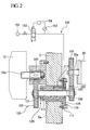
- FIG 2 is a cross-sectional view showing the constitution of the shaft seal structure 120 according to the present embodiment.
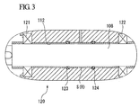
- FIG 3 is a magnified cross-sectional view of the shaft seal structure 120.
- a transmission mechanism 100 for transmitting rotation of the output shaft 20a of the cooling fan motor 20 to the cooling fan 16 is provided between the cooling fan 16 that is disposed in the cooling chamber 2 and the cooling fan motor 20 that is disposed outside of the cooling chamber 2.
- the transmission mechanism 100 is constituted from a pair of gears 101, 102 that are provided outside of the cooling chamber 2, a pair of gears 103, 104 that are provided inside of the cooling chamber 2, and a rotating shaft 108 that passes through the door 5.
- the gear 101 has 80 teeth, and is coupled to the output shaft 20a of the cooling fan motor 20.
- the gear 102 has 40 teeth and is connected to one end of a rotating shaft 108 upon meshing with the gear 101.
- the gear 103 has 80 teeth, and is coupled to the other end of the rotating shaft 108.
- the gear 104 has 25 teeth and is connected to a rotating shaft 16a of the cooling fan 16 upon meshing with the gear 103.
- the rotating shaft 108 is inserted in a through hole 112 of a bush 110 that has a flange 111 on one end, and in addition this bush 110 is fitted in a through hole 5a that is formed in the door 5.
- the rotating shaft 108 is supported by the bush 110 via the bearings 121, 122 that are provided at both ends of the through hole 112 of the bush 110.
- An O-ring 115 is disposed on the flange 111 of the bush 110, and so the flange 111 is sealed by the O-ring 115 as a result of the flange 111 abutting the outer surface of the door 5.
- the shaft seal structure 120 is disposed in the cylindrical gap that is formed between the rotating shaft 108 and the bush 110.
- the shaft seal structure 120 is constituted from two O-rings 123, 124 that are disposed in a gap between the rotating shaft 108 and the bush 110 and the grease R that is filled between the two O-rings 123, 124.
- the rotational frequency of the rotating shaft 108 is 200 rpm.
- the rotational frequency of the rotating shaft 108 is 200 rpm or less, sufficient sealing is possible with the O-rings 123, 124.
- the transmission mechanism 100 on the inside of the door 5 (interior of the cooling chamber 2), it is possible to keep the rotational frequency of the rotating shaft 108 that passes through the door 5 low while rotating the cooling fan motor 20 at a desired rotational frequency.
- the shaft seal structure 120 with a structure that is simple, moderately priced, and highly reliable as a shaft seal structure that is provided between the door 5 and the rotating shaft 108. Also, since the cooling fan motor 20 is disposed outside of the door 5 (outside of the cooling chamber 2), it is possible to use a moderately priced general-purpose motor instead of a specialized motor for use inside of the pressurized container as the cooling fan motor 20. Accordingly, it is possible to keep down the manufacturing cost of the multi-chamber heat treatment apparatus 1.
- the grease R is filled at a predetermined pressure from the flange 111 side of the bush 110 into a space S that is enclosed by the two O-rings 123, 124 within a gap that is formed between the rotating shaft 108 and the bush 110. That is, two grooves for disposing the two O-rings 123, 124 and a grease supply hole 113 that connects to the flange 111 side from between these two grooves is formed on the inner surface of the through hole 112 of the bush 110.
- An inert gas supplying portion 150 that is capable of pushing the grease R at a predetermined pressure with inert gas is coupled to the flange 111 side of the grease supply hole 113.
- the inert gas supplying portion 150 consists of a pressure source 151, a pressure sensor 152, an electromagnetic valve 153, and a pressure controller 154.
- the pressure source 151 is capable of supplying inert gas at the same pressure as the set pressure of the cooling chamber 2.
- the pressure sensor 152 indirectly measures the filling pressure of the grease R that is filled into the space S by measuring the pressure of the inert gas that has been supplied to the grease supply hole 113.
- the electromagnetic valve 153 is a valve that performs supplying and cutting off of inert gas to the grease supply hole 113 from the pressure source 151.
- the pressure controller 154 controls the electromagnetic valve 153 based on the measurement result of the pressure sensor 152.
- a treatment object that is placed on the tray 10 is placed on the transfer table 11 inside of the wind path chamber 7 in the state of the door 5 being separated from the cooling chamber 2. Then, the door is abutted against the cooling chamber 2, and the cooling chamber 2 is closed.
- the cooling chamber 2, the heating chamber 3 and the intermediate chamber 4 are evacuated by driving of a pressure reducing apparatus 57.
- the raising-lowering mechanism 26, the raising-lowering mechanism 55a, and the heat insulation door raising-lowering portion 55b are driven, whereby the conveying rod door 25, the vacuum shield door 6, and the heat insulation door 24 are opened.
- the tray 10 is engaged and pulled by the distal end portion of the conveying rod 22, whereby the treatment object X is transported from the transfer table 11 that is inside of the wind path chamber 7 onto the transfer table 28 in the heating chamber 23.
- the raising-lowering mechanism 26 and the heat insulation door raising-lowering portion once again 55b are driven, whereby the conveying rod door 25 and the heat insulation door 24 are closed.
- the raising-lowering mechanism 55a is not driven, and so the vacuum shield door 6 is maintained in an opened state. In this state, the treatment object X is heated to a predetermined temperature by the heater 29.
- the conveying rod door 25 and the heat insulation door 24 are opened, and the treatment object X is again transported to the transfer table 11 in the wind path chamber 7 by the conveying rod 22. Then, when then treatment object X has been transported to the transfer table 11 in the wind path chamber 7, the vacuum shield door 6 is hermetically sealed.
- the coolant gas is supplied to the cooling chamber 2 by a coolant gas supply apparatus 56.
- This coolant gas is circulated in the cooling chamber 2 by the cooling fan 16, whereby the treatment object X is cooled.
- the gas passage ports 19a to 19d that each close at a predetermined time by the dampers 17a and 17b, the direction in which the coolant gas flows is changed, and thereby the coolant gas is blown all over the treatment object X, so that the treatment object X is uniformly cooled.
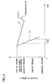
- FIG 4 shows changes in the filling pressure of the grease R of the shaft seal structure 120.
- the coolant gas that is supplied from the coolant gas supply apparatus to the cooling chamber 2 is raised to a pressure of approximately 30 atm (3.0 MPa). By pressurizing the coolant gas, it is possible to cool the treatment object X in a short time.
- the shaft seal structure 120 is capable of withstanding the difference in pressure with the outside of the cooling chamber 2 at a high probability.
- the dimension of the gap in the radial direction of the space S in a predetermined range in accordance with the hardness of the O-rings 123, 124, it is possible to suppress projection of the O-rings 123, 124 from the grooves that are formed in the inner surface of the through hole 112 of the bush 110 without using a backup ring (for example, refer to JIS-B-2406).
- the coolant gas in the cooling chamber 2 leaks to outside from the gap in which the O-rings 123, 124 are disposed, that is, the space between the rotating shaft 108 and the bush 110. As a result, there is a high possibility that the cooling process of the treatment object X may be incomplete.
- an inert gas is supplied from the pressure source 151 to the grease supply hole 113 under the control of the pressure controller 154.
- the grease R is raised to the same pressure as the inside of the cooling chamber 2 or a slightly higher pressure (for example, 31 atm (3.1 MPa), with this pressure called a first set pressure).
- the filling pressure of the grease R of the shaft seal structure 120 falls gradually (refer to line L1). This is because the grease R gradually leaks from the space S to the outside of the O-rings 123, 124, that is, to the inside or the outside of the cooling chamber 2.
- the filling pressure of the grease R of the shaft seal structure 120 is detected by the pressure sensor 152 as described above.
- the pressure controller 154 operates the electromagnetic valve 153 to resupply inert gas from the pressure source 151 to the grease supply hole 113. Thereby, the filling pressure of the grease R is again pressurized to 31 atm.
- the door 5 will be detached from the cooling chamber 2, and the processing object X will be brought outside.
- the process of cooling the treatment object X is stopped. Specifically, the coolant gas that is filled inside of the coolant chamber 2 is released from a safety valve not illustrated that is provided in the cooling chamber 2. Also, a measure is performed such as stopping driving of the cooling fan motor 20. In addition, the pressurization of the grease R of the shaft sealing configuration 120 by the inert gas supplying portion 150 is stopped, and so becomes atmospheric pressure.
- FIG 5 shows a transmission mechanism 200 and a shaft seal structure 220.
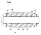
- FIG 6 is an enlarged cross-sectional view of the shaft seal structure 220.
- the shaft seal structure 220 that is a variation of the shaft seal structure 120 is constituted from three O-rings 123, 124, 125 on the rotating shaft 108 and grease R that is filled between the three O-rings 123, 124, 125.
- the grease R that is filled between the O-rings 123, 124 among the O-rings 123, 124, 125 is filled at a predetermined pressure from the flange 111 side of the bush 110 via the grease supply hole 113. That is, the inert gas supplying portion 150 is coupled to the grease supply hole 113. Note that the filling pressure of the grease R that is filled between the O-rings 124, 125 is filled at the same pressure as the outside atmosphere.
- the shaft seal structure 220 may be provided with three or more O-rings.
- the grease R that is set to the first set pressure is filled between the two O-rings 123, 124 that are closest to the cooling chamber 2. Note that the grease R that is set to the first set pressure may also be filled between the O-rings 124, 125.
- the transmission mechanism 200 that is a variation of the transmission mechanism 100 is constituted from a pair of gears 101, 102 that are provided outside of the cooling chamber 2, a pair of gears 103, 104, 105 that are provided inside of the cooling chamber 2, and a rotating shaft 108 that passes through the door 5.
- the rotational frequency of the rotating shaft 108 needs to be 200 rpm or less. This is in order to enable use of O-rings 123,124,125 as the shaft seal structure 120, 220.
- the grease R that is disposed between the O-rings may be filled at a predetermined pressure.
- the shaft seal structure 120, 220 is not limited to the case of being disposed at the door 5 of the cooling chamber 2. Provided it is a rotating shaft that passes through container wall of a pressurized container, it may be any kind of container. In this case, by coupling the inert gas supplying portion 150 to the shaft seal structure 120, 220, there is no need to detect the filling pressure of the grease R that is disposed between the plurality of O-rings.
- the shaft seal structure of the present invention can be applied to a fitting portion between a container wall of a pressurized container in which high-pressure gas is enclosed and a fitting portion with a rotating shaft that passes through this container wall.
Landscapes
- Engineering & Computer Science (AREA)
- General Engineering & Computer Science (AREA)
- Mechanical Engineering (AREA)
- Heat Treatment Of Articles (AREA)
- Sealing Devices (AREA)
- Furnace Details (AREA)
- Pressure Vessels And Lids Thereof (AREA)
Applications Claiming Priority (1)
| Application Number | Priority Date | Filing Date | Title |
|---|---|---|---|
| PCT/JP2006/307359 WO2007113920A1 (ja) | 2006-04-06 | 2006-04-06 | 冷却処理装置または多室型熱処理装置におけるシール構造、そのシール構造の圧力調整方法と運転方法 |
Publications (4)
| Publication Number | Publication Date |
|---|---|
| EP2006582A2 true EP2006582A2 (de) | 2008-12-24 |
| EP2006582A9 EP2006582A9 (de) | 2009-05-20 |
| EP2006582A4 EP2006582A4 (de) | 2012-03-21 |
| EP2006582B1 EP2006582B1 (de) | 2013-05-22 |
Family
ID=38563192
Family Applications (1)
| Application Number | Title | Priority Date | Filing Date |
|---|---|---|---|
| EP20060731307 Expired - Lifetime EP2006582B1 (de) | 2006-04-06 | 2006-04-06 | Dichtungsstruktur für eine kühlbehandlungsvorrichtung oder eine mehrkammer-wärmbehandlungsvorrichtung, und für die dichtungsstruktur druckregelverfahren und betriebsverfahren |
Country Status (6)
| Country | Link |
|---|---|
| US (1) | US8734147B2 (de) |
| EP (1) | EP2006582B1 (de) |
| JP (1) | JP5200929B2 (de) |
| KR (1) | KR101195080B1 (de) |
| CN (1) | CN101460770B (de) |
| WO (1) | WO2007113920A1 (de) |
Cited By (1)
| Publication number | Priority date | Publication date | Assignee | Title |
|---|---|---|---|---|
| US8992213B2 (en) | 2009-02-03 | 2015-03-31 | Ipsen, Inc. | Sealing mechanism for a vacuum heat treating furnace |
Families Citing this family (7)
| Publication number | Priority date | Publication date | Assignee | Title |
|---|---|---|---|---|
| JP2010038531A (ja) * | 2008-07-10 | 2010-02-18 | Ihi Corp | 熱処理装置 |
| CN102943880B (zh) * | 2012-10-30 | 2015-06-03 | 中国核电工程有限公司 | 一种轴传动的密封系统 |
| KR101716361B1 (ko) * | 2014-12-29 | 2017-03-14 | 씰링크 주식회사 | 누출감지 기능이 있는 구동축용 밀폐장치 |
| WO2016189919A1 (ja) | 2015-05-26 | 2016-12-01 | 株式会社Ihi | 熱処理装置 |
| CN110106335B (zh) * | 2018-02-01 | 2021-04-13 | 福建省长汀金龙稀土有限公司 | 一种合金工件或金属工件的连续热处理装置以及方法 |
| EP3575641A1 (de) * | 2018-05-30 | 2019-12-04 | Siemens Aktiengesellschaft | Anordnung, insbesondere turbomaschine, umfassend eine wellendichtungseinrichtung |
| CN112859955B (zh) * | 2021-01-22 | 2022-08-26 | 维沃移动通信有限公司 | 温控装置及其温度控制方法 |
Family Cites Families (24)
| Publication number | Priority date | Publication date | Assignee | Title |
|---|---|---|---|---|
| US3467396A (en) * | 1967-05-10 | 1969-09-16 | Durametallic Corp | Internally cooled seal assembly |
| JPS5653872Y2 (de) * | 1978-07-05 | 1981-12-15 | ||
| JPS6225799A (ja) | 1985-07-27 | 1987-02-03 | ソニー株式会社 | 音声認識装置 |
| GB8520526D0 (en) * | 1985-08-15 | 1985-09-18 | Brown Bros & Co Ltd | Sealing apparatus for fluids |
| JPS6337679Y2 (de) * | 1986-08-07 | 1988-10-05 | ||
| US5209495A (en) * | 1990-09-04 | 1993-05-11 | Palmour Harold H | Reciprocating rod pump seal assembly |
| JP2535684B2 (ja) | 1991-08-10 | 1996-09-18 | 矢野 和也 | 砥石車とその製造方法 |
| JPH0547798U (ja) * | 1991-11-13 | 1993-06-25 | 石川島播磨重工業株式会社 | 炉における軸貫通部のシール構造 |
| JPH05296352A (ja) * | 1992-04-14 | 1993-11-09 | Toyo Kogyo Kk | 軸受シールにおける給油装置 |
| US5669636A (en) * | 1995-08-01 | 1997-09-23 | Deublin Company | Floating seal assembly for a bearingless coolant union having air rotation capability |
| KR100486118B1 (ko) | 1996-05-09 | 2005-08-31 | 프라마톰 아엔페 게엠베하 | 산업용설비의동작을시뮬레이션하기위한방법및장치 |
| JP2001132847A (ja) * | 1999-11-04 | 2001-05-18 | Mitsui Zosen Akishima Kenkyusho:Kk | 回転軸用シール装置 |
| JP2001173794A (ja) * | 1999-12-17 | 2001-06-26 | Furukawa Co Ltd | ポンプの軸封装置 |
| US6431553B1 (en) * | 2000-08-28 | 2002-08-13 | The United States Of America As Represented By The Secretary Of The Navy | Radially pressure balanced floating seal system |
| US6467774B1 (en) * | 2000-08-28 | 2002-10-22 | The United States Of America As Represented By The Secretary Of The Navy | Axially pressure balanced floating seal system |
| JP2002228010A (ja) | 2000-10-25 | 2002-08-14 | Teijin Seiki Co Ltd | 真空シール機構および真空シール装置 |
| TW544470B (en) * | 2001-02-22 | 2003-08-01 | Chugai Ro Kogyo Kaisha Ltd | A gas-cooled single-chamber type heat-treating furnace and a gas cooling process in the furnace |
| KR200297439Y1 (ko) | 2002-05-13 | 2002-12-12 | 주식회사 포스코 | 그리스 자동공급 기능을 갖는 회전축 실링장치 |
| DE602004027043D1 (de) | 2003-06-27 | 2010-06-17 | Ihi Corp | Vakuumwärmebehandlungsofen der gaskühlart und kühlgasrichtungsschaltvorrichtung |
| JP4280981B2 (ja) | 2003-06-27 | 2009-06-17 | 株式会社Ihi | 真空熱処理炉の冷却ガス風路切替え装置 |
| JP4441903B2 (ja) | 2003-07-11 | 2010-03-31 | 株式会社Ihi | 高速循環ガス冷却式真空熱処理炉 |
| FI117108B (fi) * | 2004-02-10 | 2006-06-15 | Crane John Safematic Oy | Sovitelma mekaanisen akselitiivisteen yhteydessä |
| US7504896B2 (en) | 2006-09-06 | 2009-03-17 | International Business Machines Corporation | Methods and apparatus for inline measurement of switching delay history effects in PD-SOI technology |
| US7971854B2 (en) * | 2007-09-24 | 2011-07-05 | Griswold Controls Inc | Replaceable valve shaft sealing system |
-
2006
- 2006-04-06 EP EP20060731307 patent/EP2006582B1/de not_active Expired - Lifetime
- 2006-04-06 US US12/295,924 patent/US8734147B2/en active Active
- 2006-04-06 WO PCT/JP2006/307359 patent/WO2007113920A1/ja not_active Ceased
- 2006-04-06 JP JP2008508444A patent/JP5200929B2/ja not_active Expired - Fee Related
- 2006-04-06 CN CN2006800548397A patent/CN101460770B/zh not_active Expired - Fee Related
- 2006-04-06 KR KR1020087026809A patent/KR101195080B1/ko not_active Expired - Fee Related
Cited By (1)
| Publication number | Priority date | Publication date | Assignee | Title |
|---|---|---|---|---|
| US8992213B2 (en) | 2009-02-03 | 2015-03-31 | Ipsen, Inc. | Sealing mechanism for a vacuum heat treating furnace |
Also Published As
| Publication number | Publication date |
|---|---|
| KR20090005136A (ko) | 2009-01-12 |
| KR101195080B1 (ko) | 2012-10-29 |
| EP2006582A9 (de) | 2009-05-20 |
| EP2006582A4 (de) | 2012-03-21 |
| CN101460770A (zh) | 2009-06-17 |
| US20090186311A1 (en) | 2009-07-23 |
| EP2006582B1 (de) | 2013-05-22 |
| WO2007113920A1 (ja) | 2007-10-11 |
| JPWO2007113920A1 (ja) | 2009-08-13 |
| JP5200929B2 (ja) | 2013-06-05 |
| CN101460770B (zh) | 2012-09-26 |
| US8734147B2 (en) | 2014-05-27 |
Similar Documents
| Publication | Publication Date | Title |
|---|---|---|
| US6910614B2 (en) | Vacuum compression brazing furnace and method of using same | |
| JP5407153B2 (ja) | 単室型真空熱処理炉 | |
| US8734147B2 (en) | Seal structure for pressurized container, cooling treatment apparatus, multi-chamber heat treatment apparatus, pressure regulating method, and operating method | |
| US8652370B2 (en) | Hot isostatic pressing method and apparatus | |
| JPWO2005090616A1 (ja) | 2室型熱処理炉 | |
| EP1801529B1 (de) | Kühlgasdurchgangsschalteinrichtung für unterdruckwärmebehandlungsofen | |
| CN107342244A (zh) | 热处理装置 | |
| US10690416B2 (en) | Heat treatment device | |
| EP1472038B1 (de) | Vakuumverdichteter lötofen und verfahren zu dessen verwendung | |
| JP5635819B2 (ja) | 熱処理加工方法及び熱処理加工装置 | |
| KR101930445B1 (ko) | 자동차 조향장치 인텀샤프트용 정밀 이형 인발강관의 개방형 극소탈탄 연속 열처리 시스템 | |
| KR100687799B1 (ko) | 냉매 순환식 수직 진공 열처리로 및 진공 열처리 방법 | |
| JP6427949B2 (ja) | 真空焼入れ処理方法 | |
| KR102089162B1 (ko) | 고로 냉각 장치 | |
| JP7544995B1 (ja) | 熱処理装置 | |
| TWI362446B (de) | ||
| JP6046555B2 (ja) | 焼鈍処理における急冷方法及び焼鈍炉における急冷設備 | |
| CN213623845U (zh) | 钢化玻璃冷却装置及玻璃钢化设备 | |
| JP2010139133A (ja) | 熱処理装置およびこれを用いた熱処理方法 | |
| KR100765049B1 (ko) | 가열로 장입측 이송롤 테이블의 롤 축수부 냉각장치 | |
| KR20220074072A (ko) | 급냉 가능한 대차식 열처리 시스템 | |
| JP2019203186A (ja) | 熱処理装置および金属部品の製造方法 | |
| WO2007086173A1 (ja) | ガス雰囲気熱処理装置及び方法 | |
| JP2001221575A (ja) | 真空炉 | |
| JPH06277490A (ja) | オートクレーブのガス温度制御装置 |
Legal Events
| Date | Code | Title | Description |
|---|---|---|---|
| PUAI | Public reference made under article 153(3) epc to a published international application that has entered the european phase |
Free format text: ORIGINAL CODE: 0009012 |
|
| PUAB | Information related to the publication of an a document modified or deleted |
Free format text: ORIGINAL CODE: 0009199EPPU |
|
| 17P | Request for examination filed |
Effective date: 20081010 |
|
| AK | Designated contracting states |
Kind code of ref document: A2 Designated state(s): DE FR GB |
|
| DAX | Request for extension of the european patent (deleted) | ||
| RBV | Designated contracting states (corrected) |
Designated state(s): DE FR GB |
|
| A4 | Supplementary search report drawn up and despatched |
Effective date: 20120220 |
|
| RIC1 | Information provided on ipc code assigned before grant |
Ipc: F16J 15/16 20060101AFI20120214BHEP Ipc: F27D 9/00 20060101ALI20120214BHEP Ipc: F27D 7/06 20060101ALI20120214BHEP |
|
| GRAP | Despatch of communication of intention to grant a patent |
Free format text: ORIGINAL CODE: EPIDOSNIGR1 |
|
| RIN1 | Information on inventor provided before grant (corrected) |
Inventor name: KATSUMATA, KAZUHIKO C/O IHI CORPORATION |
|
| GRAS | Grant fee paid |
Free format text: ORIGINAL CODE: EPIDOSNIGR3 |
|
| GRAA | (expected) grant |
Free format text: ORIGINAL CODE: 0009210 |
|
| AK | Designated contracting states |
Kind code of ref document: B1 Designated state(s): DE FR GB |
|
| REG | Reference to a national code |
Ref country code: GB Ref legal event code: FG4D |
|
| REG | Reference to a national code |
Ref country code: DE Ref legal event code: R096 Ref document number: 602006036416 Country of ref document: DE Effective date: 20130718 |
|
| PLBE | No opposition filed within time limit |
Free format text: ORIGINAL CODE: 0009261 |
|
| STAA | Information on the status of an ep patent application or granted ep patent |
Free format text: STATUS: NO OPPOSITION FILED WITHIN TIME LIMIT |
|
| 26N | No opposition filed |
Effective date: 20140225 |
|
| REG | Reference to a national code |
Ref country code: DE Ref legal event code: R097 Ref document number: 602006036416 Country of ref document: DE Effective date: 20140225 |
|
| PGFP | Annual fee paid to national office [announced via postgrant information from national office to epo] |
Ref country code: GB Payment date: 20140402 Year of fee payment: 9 |
|
| PGFP | Annual fee paid to national office [announced via postgrant information from national office to epo] |
Ref country code: FR Payment date: 20140409 Year of fee payment: 9 |
|
| GBPC | Gb: european patent ceased through non-payment of renewal fee |
Effective date: 20150406 |
|
| PG25 | Lapsed in a contracting state [announced via postgrant information from national office to epo] |
Ref country code: GB Free format text: LAPSE BECAUSE OF NON-PAYMENT OF DUE FEES Effective date: 20150406 |
|
| REG | Reference to a national code |
Ref country code: FR Ref legal event code: ST Effective date: 20151231 |
|
| PG25 | Lapsed in a contracting state [announced via postgrant information from national office to epo] |
Ref country code: FR Free format text: LAPSE BECAUSE OF NON-PAYMENT OF DUE FEES Effective date: 20150430 |
|
| PGFP | Annual fee paid to national office [announced via postgrant information from national office to epo] |
Ref country code: DE Payment date: 20210316 Year of fee payment: 16 |
|
| REG | Reference to a national code |
Ref country code: DE Ref legal event code: R119 Ref document number: 602006036416 Country of ref document: DE |
|
| PG25 | Lapsed in a contracting state [announced via postgrant information from national office to epo] |
Ref country code: DE Free format text: LAPSE BECAUSE OF NON-PAYMENT OF DUE FEES Effective date: 20221103 |