EP2006588A2 - Soupape microfluidique, son procédé de fabrication et dispositif microfluidique comprenant la soupape microfluidique - Google Patents
Soupape microfluidique, son procédé de fabrication et dispositif microfluidique comprenant la soupape microfluidique Download PDFInfo
- Publication number
- EP2006588A2 EP2006588A2 EP20080158046 EP08158046A EP2006588A2 EP 2006588 A2 EP2006588 A2 EP 2006588A2 EP 20080158046 EP20080158046 EP 20080158046 EP 08158046 A EP08158046 A EP 08158046A EP 2006588 A2 EP2006588 A2 EP 2006588A2
- Authority
- EP
- European Patent Office
- Prior art keywords
- valve
- microfluidic
- channel
- protruding pattern
- lower substrate
- Prior art date
- Legal status (The legal status is an assumption and is not a legal conclusion. Google has not performed a legal analysis and makes no representation as to the accuracy of the status listed.)
- Withdrawn
Links
Images







Classifications
-
- F—MECHANICAL ENGINEERING; LIGHTING; HEATING; WEAPONS; BLASTING
- F16—ENGINEERING ELEMENTS AND UNITS; GENERAL MEASURES FOR PRODUCING AND MAINTAINING EFFECTIVE FUNCTIONING OF MACHINES OR INSTALLATIONS; THERMAL INSULATION IN GENERAL
- F16K—VALVES; TAPS; COCKS; ACTUATING-FLOATS; DEVICES FOR VENTING OR AERATING
- F16K99/00—Subject matter not provided for in other groups of this subclass
- F16K99/0001—Microvalves
-
- F—MECHANICAL ENGINEERING; LIGHTING; HEATING; WEAPONS; BLASTING
- F16—ENGINEERING ELEMENTS AND UNITS; GENERAL MEASURES FOR PRODUCING AND MAINTAINING EFFECTIVE FUNCTIONING OF MACHINES OR INSTALLATIONS; THERMAL INSULATION IN GENERAL
- F16K—VALVES; TAPS; COCKS; ACTUATING-FLOATS; DEVICES FOR VENTING OR AERATING
- F16K99/00—Subject matter not provided for in other groups of this subclass
- F16K99/0001—Microvalves
- F16K99/0003—Constructional types of microvalves; Details of the cutting-off member
- F16K99/0032—Constructional types of microvalves; Details of the cutting-off member using phase transition or influencing viscosity
-
- F—MECHANICAL ENGINEERING; LIGHTING; HEATING; WEAPONS; BLASTING
- F16—ENGINEERING ELEMENTS AND UNITS; GENERAL MEASURES FOR PRODUCING AND MAINTAINING EFFECTIVE FUNCTIONING OF MACHINES OR INSTALLATIONS; THERMAL INSULATION IN GENERAL
- F16K—VALVES; TAPS; COCKS; ACTUATING-FLOATS; DEVICES FOR VENTING OR AERATING
- F16K99/00—Subject matter not provided for in other groups of this subclass
- F16K99/0001—Microvalves
- F16K99/0034—Operating means specially adapted for microvalves
- F16K99/0036—Operating means specially adapted for microvalves operated by temperature variations
- F16K99/004—Operating means specially adapted for microvalves operated by temperature variations using radiation
-
- F—MECHANICAL ENGINEERING; LIGHTING; HEATING; WEAPONS; BLASTING
- F16—ENGINEERING ELEMENTS AND UNITS; GENERAL MEASURES FOR PRODUCING AND MAINTAINING EFFECTIVE FUNCTIONING OF MACHINES OR INSTALLATIONS; THERMAL INSULATION IN GENERAL
- F16K—VALVES; TAPS; COCKS; ACTUATING-FLOATS; DEVICES FOR VENTING OR AERATING
- F16K99/00—Subject matter not provided for in other groups of this subclass
- F16K2099/0082—Microvalves adapted for a particular use
- F16K2099/0084—Chemistry or biology, e.g. "lab-on-a-chip" technology
-
- Y—GENERAL TAGGING OF NEW TECHNOLOGICAL DEVELOPMENTS; GENERAL TAGGING OF CROSS-SECTIONAL TECHNOLOGIES SPANNING OVER SEVERAL SECTIONS OF THE IPC; TECHNICAL SUBJECTS COVERED BY FORMER USPC CROSS-REFERENCE ART COLLECTIONS [XRACs] AND DIGESTS
- Y10—TECHNICAL SUBJECTS COVERED BY FORMER USPC
- Y10T—TECHNICAL SUBJECTS COVERED BY FORMER US CLASSIFICATION
- Y10T137/00—Fluid handling
- Y10T137/206—Flow affected by fluid contact, energy field or coanda effect [e.g., pure fluid device or system]
- Y10T137/218—Means to regulate or vary operation of device
- Y10T137/2191—By non-fluid energy field affecting input [e.g., transducer]
-
- Y—GENERAL TAGGING OF NEW TECHNOLOGICAL DEVELOPMENTS; GENERAL TAGGING OF CROSS-SECTIONAL TECHNOLOGIES SPANNING OVER SEVERAL SECTIONS OF THE IPC; TECHNICAL SUBJECTS COVERED BY FORMER USPC CROSS-REFERENCE ART COLLECTIONS [XRACs] AND DIGESTS
- Y10—TECHNICAL SUBJECTS COVERED BY FORMER USPC
- Y10T—TECHNICAL SUBJECTS COVERED BY FORMER US CLASSIFICATION
- Y10T137/00—Fluid handling
- Y10T137/206—Flow affected by fluid contact, energy field or coanda effect [e.g., pure fluid device or system]
- Y10T137/218—Means to regulate or vary operation of device
- Y10T137/2191—By non-fluid energy field affecting input [e.g., transducer]
- Y10T137/2196—Acoustical or thermal energy
-
- Y—GENERAL TAGGING OF NEW TECHNOLOGICAL DEVELOPMENTS; GENERAL TAGGING OF CROSS-SECTIONAL TECHNOLOGIES SPANNING OVER SEVERAL SECTIONS OF THE IPC; TECHNICAL SUBJECTS COVERED BY FORMER USPC CROSS-REFERENCE ART COLLECTIONS [XRACs] AND DIGESTS
- Y10—TECHNICAL SUBJECTS COVERED BY FORMER USPC
- Y10T—TECHNICAL SUBJECTS COVERED BY FORMER US CLASSIFICATION
- Y10T29/00—Metal working
- Y10T29/49—Method of mechanical manufacture
- Y10T29/49405—Valve or choke making
- Y10T29/49412—Valve or choke making with assembly, disassembly or composite article making
Definitions
- the present invention relates to a microfluidic valve, and more particularly, to a microfluidic valve for controlling flow of a fluid through structures in a platform , a method of manufacturing the microfluidic valve, and a microfluidic device comprising the microfluidic valve.
- microfluidic devices Devices that perform a biological or chemical reaction by manipulating a small volume of fluid are referred to as microfluidic devices.
- a microfluidic device includes microfluidic structures disposed in a platform, wherein the platform can have various shapes such as a chip shape or a disc shape.
- the microfluidic structures include chambers that can hold a fluid, channels through which the fluid can flow, and valves that can control the flow of the fluid.
- microfluidic devices can be manufactured by various combinations of these elements.
- a device manufactured to perform various steps of fluid treatment and manipulation including experiments of biological reactions by disposing microfluidic structures in a flat chip form is referred to as a lab-on-a chip.
- a driving pressure is required.
- a capillary force or pressure generated by an additional pump is used.
- disc type microfluidic devices that perform a series of operations by having microfluidic structures disposed in a flat disc form and moving a fluid through the microfluidic structures using centrifugal force have been disclosed. This type of device is referred to as a Lab CD or a Lab-on a disc.
- microfluidic valves In order to perform complicated processes in microfluidic devices such as a Lab CD or a Lab-on a disc, a plurality of microfluidic valves that can individually control the flow of a fluid by being disposed in various positions are required. Also, in order to mass produce the microfluidic devices, a method of efficiently manufacturing the microfluidic valves together with chambers and channels is required.
- a method of controlling the flow of a fluid using a phase change material that is a solid state at room temperature and is smelted at a high temperature has been proposed.
- a biochemical reaction substrate published in Anal. Chem. Vol. 76, 2004, pp1824 ⁇ 1831 includes a valve formed of paraffin wax and a heating element for smelting the paraffin wax.
- the valve included in the above substrates requires a large amount of paraffin wax in order to close minute channels, and a large heating element must be included to smelt the large amount of paraffin wax.
- a long heating time is required to smelt the paraffin wax and it is difficult to precisely control the opening time of channels.
- the present invention provides a microfluidic valve that rapidly and accurately performs the operation of controlling flow of a fluid through structures in a platform by application of an external electromagnetic wave energy source and a microfluidic device comprising the same.
- the present invention also provides a method of manufacturing the microfluidic valve with increased reliability and efficiency.
- the present invention provides a method of manufacturing the microfluidic valve, in which processes of manufacturing the microfluidic valve have minimal influence on other constituent elements when a microfluidic device that includes the microfluidic valve is manufactured.
- a microfluidic valve comprising: a platform that comprises two substrates combined facing each other; a channel having a first depth so that a fluid flow between the two substrates; a valve gap that is disposed on at least a region of the channel and has a second depth which is shallower than the first depth; and a valve plug that is disposed to fill the valve gap and is formed of a valve material made by mixing a phase change material, which is solid at room temperature, with a plurality of exothermic particles that emit an amount of heat sufficient to smelt the phase change material by absorbing electromagnetic waves.
- the two substrates may be combined to each other by combining portions that comprise at least the outer walls of the channel. At least one of the two substrates comprises a protruding pattern formed along the outer walls of the channel and a surface of the protruding pattern is combined with a surface of the substrate that faces the protruding pattern.
- the microfluidic valve may further comprising a valve material chamber disposed close to the channel to accommodate a valve material for forming the valve plug and connected to the valve gap so that smelted valve material moves to the valve gap.
- the two substrates may be combined to each other by combining portions that at least comprise outer walls of the channel and the valve material chamber.
- At least one of the two substrates may comprise a protruding pattern formed along the outer walls of the channel and the valve material chamber, and a surface of the protruding pattern may be combined with a surface of the substrate that faces the protruding pattern.
- the phase change material may be one selected from the group consisting of a wax, a gel, and a thermoplastic resin.
- the wax may be one selected from the group consisting of paraffin wax, microcrystalline wax, synthetic wax, and natural wax.
- the gel may be one selected from the group consisting of polyacrylamide, polyacrylates, polymethacrylates, and polyvinylamides.
- the thermoplastic resin may be one selected from the group consisting of cyclic olefin copolymer (COC), polymethylmethacrylate (PMMA), polycarbonate (PC), polystyrene (PS), polyoxymethylene (POM), (perfluoralkoxy (PFA), polyvinylchloride (PVC), polypropylene (PP), polyethylene terephthalate (PET), polyetheretherketone (PEEK), polyamide (PA), polysulfone (PSU), and polyvinylidene fluoride (PVDF).
- COC cyclic olefin copolymer
- PMMA polymethylmethacrylate
- PC polycarbonate
- PS polystyrene
- POM polyoxymethylene
- PFA perfluoralkoxy
- PVC polyvinylchloride
- PP polypropylene
- PET polyethylene terephthalate
- PEEK polyetheretherketone
- PA polyamide
- PSU polysulfone
- the exothermic particles may be metal oxide particles.
- the metal oxide particles may include at least one selected from the group consisting of Al 2 O 3 , TiO 2 , Ta 2 O 3 , Fe 2 O 3 , Fe 3 O 4 , and HfO 2 .
- the exothermic particles may be polymer particles, quantum dots, or magnetic beads.
- a method of manufacturing a microfluidic valve comprising: (a) preparing an upper substrate and a lower substrate, which have a three-dimensional structure allowing formation of a channel having a first depth and a valve gap having a second depth formed in at least a portion of the channel region between the two substrates which face each other, wherein the second depth is shallower than the first depth; (b) distributing a smelted valve material on a location of the lower substrate corresponding to the valve gap and solidifying the valve material; (c) forming a platform by combining the upper substrate and the lower substrate; and (d) forming a valve plug by filling the valve gap with the valve material in a smelted state through the application of heat to the valve material from outside of the platform and then allowing the valve material to re-solidify in the valve gap, wherein the valve material is made by mixing a phase change material, which is a solid state at room temperature, with a plurality of exothermic particles that emit an amount
- the operation of (a) may comprise preparing a lower substrate having a three-dimensional structure that forms the channel and the valve gap on an upper surface thereof, and preparing an upper substrate that at least covers a region that comprises the three-dimensional structure. Also, the operation of (a) may comprise preparing a lower substrate having a three-dimensional structure which forms the channel, the valve gap, and a valve material chamber connected to the valve gap formed on an upper surface thereof, and an upper substrate that at least covers at least a region that comprises the three-dimensional structure, the operation of (b) may comprise disposing the valve material in the valve material chamber, and the operation of (d) may comprise filling the valve gap by moving the smelted valve material to the valve gap.
- the operation of (a) may comprise a lower substrate that further comprises a protruding pattern formed along the outer walls of the three-dimensional structure, and an upper substrate that at least covers a region that comprises the three-dimensional structure and the protruding pattern
- the operation of (c) may comprise combining the lower substrate by covering it with the upper substrate after an adhesive is coated on a surface of the protruding pattern of the lower substrate.
- the operation (a) may comprise preparing a lower substrate that comprises a protruding pattern formed along the outer walls of the three-dimensional structure and an upper substrate that at least covers a region that covers the three-dimensional structure and the protruding pattern, and the operation of (c) may comprise combining the lower substrate by covering with the upper substrate after coating an adhesive on the upper substrate in a shape corresponding to the shape of the protruding pattern.
- the operation (d) may comprise radiating electromagnetic waves to the valve material until a portion of the valve material in the valve material chamber vaporizes, and moving the smelted valve material into the valve gap by vapor pressure of the vaporized valve material.
- a microfluidic device comprising: a platform that comprises two substrates combined facing each other; and a microfluidic structure that is disposed in the platform and comprises at least a chamber, a channel, and a microfluidic valve for manipulating a microfluid, wherein the microfluidic valve comprises: a channel having a first depth to allow a fluid to flow between the two substrates; a valve gap that is disposed on at least a region of the channel and has a second depth which is shallower than the first depth; and a valve plug that is disposed to fill the valve gap and is formed of a valve material made by mixing a phase change material, which is solid at room temperature, with a plurality of exothermic particles that emit an amount of heat sufficient to smelt the phase change material by absorbing electromagnetic waves.
- the two substrates may be combined to each other by combining portions that at least comprise outer walls of the microfluidic structure. At least one of the two substrates may comprise a protruding pattern formed along the outer walls of the microfluidic structure, and a surface of the protruding pattern may be combined with a surface of the substrate that faces the protruding pattern.
- the microfluidic device may further comprise a valve material chamber disposed close to the channel to accommodate the valve material for forming the valve plug and connected to the valve gap so that the valve material in a fluid state moves to the valve gap.
- the platform may have a rotatable disc shape, and a fluid in the microfluidic structure may be moved by centrifugal force generated by rotation of the platform.
- FIG. 1 is a perspective view of a microfluidic valve 10 according to an embodiment of the present invention.
- FIG. 2 is a cross-sectional view taken along line II-II' of the microfluidic valve 10 of FIG. 1 .
- the microfluidic valve 10 in FIGS. 1 and 2 is an example of a microfluidic valve that can be employed in a microfluidic device that performs a biological or chemical reaction by manipulating a minute fluid in a platform 100.
- the platform 100 can have various shapes and forms such as a chip of a rectangular shape, or a disc shape, a fan shape, or a trapezoidal shape.
- Both ends of a channel 20 of the microfluidic valve 10 can be connected to structures such as a chamber or other channels disposed in the platform 100 of the same type (refer to FIG. 9 ).
- the platform 100 can be formed of a plastic material that is easily molded and a surface of which is biologically inactive, such as polymethyl methacrylate (PMMA), polydimethylsiloxane (PDMS), or polycarbonate (PC).
- PMMA polymethyl methacrylate
- PDMS polydimethylsiloxane
- PC polycarbonate
- the materials for forming the platform 100 are not limited thereto, that is, any material that has chemical and biological stability, optical transparency, and mechanical processability can be used.
- the platform 100 can be made of an upper substrate 120 and a lower substrate 110.
- a space for storing or flowing a fluid can be provided by combining three-dimensional structures (for example, three-dimensional structures formed by engraving) corresponding to a chamber (not shown) or a channel 20 on surfaces of the upper substrate 120 and the lower substrate 110 facing each other.
- the combining of the upper substrate 120 and the lower substrate 110 can be achieved by various methods such as bonding using an adhesive or a dual-sided tape, solvent bonding
- the microfluidic valve 10 includes the channel 20 having a first depth D1 and a valve gap G that is disposed in a portion of the channel 20 and has a second depth D2 smaller than the first depth D1.
- the valve gap G is defined by an upper surface of a valve gap forming unit 21 which protrudes from the bottom of the channel 20 and a lower surface of the upper substrate 120 of the platform 100.
- the second depth D2 of the valve gap G can be a depth that can be filled with a valve material (which will be described later) by a capillary force when the valve material is smelted.
- the actual size of the second depth D2 can be determined in consideration of various factors such as a contact angle between the smelted material and the upper and lower substrate 120 and 110. As an example, when the depth D1 of the channel 20 is 1 mm, the second depth D2 of the valve gap G can be 0.1 mm.
- a valve plug 33 that blocks the flow of the fluid through the valve gap G is disposed in the valve gap G.
- the valve plug 33 fills the valve gap G in a widthwise direction in a process of re-solidifying the valve material after the valve material disposed in the valve gap G is smelted in the course of manufacturing the microfluidic valve 10 by electromagnetic wave energy radiated from the outside of the platform 100.
- the valve material that constitutes the valve plug 33 is made by mixing a phase change material with a plurality of exothermic particles that emit heat to some degree by absorbing electromagnetic wave energy, thus smelting the phase change material.
- the phase change material can be wax. When the wax is heated, the wax turns to liquid state by smelting.
- the wax can be a paraffin wax, a microcrystalline wax, a synthetic wax, or a natural wax.
- the phase change material can be a gel or a thermoplastic resin.
- the gel can be polyacrylamide, polyacrylates, polymethacrylates, or polyvinylamides.
- the thermoplastic resin can be cyclic olefin copolymer (COC), polymethylmethacrylate (PMMA), polycarbonate (PC), polystyrene (PS), polyoxymethylene (POM), (perfluoralkoxy (PFA), polyvinylchloride (PVC), polypropylene (PP), polyethylene terephthalate (PET), polyetheretherketone (PEEK), polyamide (PA), polysulfone (PSU), or polyvinylidene fluoride (PVDF).
- COC cyclic olefin copolymer
- PMMA polymethylmethacrylate
- PC polycarbonate
- PS polystyrene
- POM polyoxymethylene
- PFA perfluoralkoxy
- PVC polyvinylchloride
- PP polyprop
- the exothermic particles can have a diameter of 1 nm to 100 ⁇ m so that the exothermic particles can freely move in the valve gap G.
- the exothermic particles have a characteristic of emitting heat by rapidly increasing temperature when electromagnetic wave energy is supplied, for example, by radiating a laser, and being uniformly distributed in the wax.
- Each of the exothermic particles can have a structure of a core including a metal component and a hydrophobic surface surrounding the core in order to have the above characteristic.
- the exothermic particle can have a particle structure including a core formed of Fe and a plurality of surfactant components that surroundingly combine with Fe.
- the exothermic particles are conventionally kept in a state in which the exothermic particles are dispersed in a carrier oil.
- the carrier oil may also be hydrophobic so that the exothermic particles having a hydrophobic surface structure can be uniformly dispersed in the carrier oil.
- the valve material can be made by mixing the smelted phase change material with the carrier oil in which the exothermic particles are dispersed.
- the exothermic particles are not limited to specific shapes, and other forms such as quantum dots or magnetic beads can be used. Also, the exothermic particles can be metal oxide particles, for example, Al 2 O 3 , TiO 2 , Ta 2 O 3 , Fe 2 O 3 , Fe 3 O 4 , or HfO 2 .
- the upper substrate 120 and the lower substrate 110 that constitute the platform 100 have a combining unit 115 in which portions of surfaces facing each other are combined.
- the combining unit 115 includes outer walls of the channel 20 to prevent the fluid from leaking.
- the combining unit 115 can be formed in a band shape along the outer wall of the channel 20.
- the combining unit 115 can be formed in various shapes according to the method of joining the upper substrate 120 and the lower substrate 110. For example, if an adhesive is used, the adhesive is coated either on a lower surface of the upper substrate 120 or an upper surface of the lower substrate 110 having a shape described above using a patterning method such as an ink jet printing method, and afterwards, the upper substrate 120 and the lower substrate 110 are joined to each other.
- the combining unit 115 can include a protruding pattern (not shown) formed to surround the outer walls of the channel 20.
- a protruding pattern (not shown) formed to surround the outer walls of the channel 20.
- the surface of the protruding pattern can be combined to the lower surface of the upper substrate 120.
- the microfluidic valve 10 described above is a normally closed valve. That is, before operating, the microfluidic valve 10 blocks flow of fluid by closing the valve gap G, however, during operation, the microfluidic valve 10 allows the flow of fluid by opening the valve gap G.
- an electromagnetic wave energy source identical to the electromagnetic wave energy source used for forming the valve plug 33 can be used.
- an electromagnetic wave for example, a laser beam is radiated onto the valve plug 33, exothermic particles dispersed in the valve plug 33 rapidly emit heat by absorbing the electromagnetic wave energy.
- the phase change material is smelted by the heat, and thus, the valve material that constitutes the valve plug 33 has fluidity.
- the melted valve material is moved to a deeper portion of the channel 20 outside the valve gap G. As a result, a fluid can flow through the channel 20.
- the results of an experiment for the measuring reaction time of the microfluidic valve 10 are as follows.
- pressure of a fluid was maintained at 46kPa.
- a syringe pump Havard PHD2000, USA
- a pressure sensor MPX 5500DP, Freescale semiconductor Inc., AZ, USA
- Emission wavelength of the electromagnetic wave energy source was 808nm, and a laser light source having an output of 1.5W was used.
- Data regarding the reaction time of the microfluidic valve 10 was obtained from the analysis of resultant pictures taken by a high speed camera (Fastcam-1024, Photron, CA, USA).
- the valve material was made by mixing a ferrofluid, in which magnetic beads having an average diameter of 10nm as the exothermic particles were dispersed in a carrier oil, with paraffin wax were mixed 1:1, that is, a magnetic wax in which a volume fraction of the ferrofluid is 50% was used.
- a ferrofluid in which magnetic beads having an average diameter of 10nm as the exothermic particles were dispersed in a carrier oil, with paraffin wax were mixed 1:1, that is, a magnetic wax in which a volume fraction of the ferrofluid is 50% was used.
- the higher the volume fraction of the ferrofluid the shorter the reaction time.
- the volume fraction of the ferrofluid is 70% or more, the maximum hold-up pressure of the valve plug 33 is reduced.
- the volume fraction of the ferrofluid to be included in the valve plug 33 of the microfluidic valve 10 can be determined through consideration of the requirement of reaction time and the requirement of maximum hold-up pressure.
- the reaction time of wax valve from when commencing of radiating of a laser beam onto the valve plug 33 of the microfluidic valve 10 to open the channel by smelting the valve plug 33 was 0.012 sec. Considering that a conventional reaction time of wax valve is 2 to 10 seconds, the reaction time of wax valve according to the present embodiment is significantly short.
- FIG. 3 is a perspective view of a microfluidic valve 11 according to another embodiment of the present invention.
- FIG. 4 is a cross-sectional view taken along line IV-IV' of the microfluidic valve of FIG. 3 .
- the microfluidic valve 11 according to the present embodiment further includes a valve material chamber 22 that stores a valve material for forming a valve plug 34.
- the valve material chamber 22 is disposed close to the valve gap G and is connected to the valve gap G.
- the valve material filled in the valve material chamber 22 moves into the valve gap G in a smelted state obtained by the application of an electromagnetic wave energy source (not shown) supplied from outside of the platform 100 and forms the valve plug 34 by re-solidifying.
- the combining unit 115 may be formed along outer walls of the channel 20 and the valve material chamber 22.
- the microfluidic valve 11 can be used as a normally closed valve like the microfluidic valve 10 of FIG. 1 , and can also be used as a normally opened valve. If the microfluidic valve 11 is used as a normally opened valve, the microfluidic valve 11 can be in a state in which the valve gap G is opened and the valve material chamber 22 is filled with the valve material. In order to block the flow of fluid through the channel 20, the valve material filled in the valve material chamber 22 is smelted by applying electromagnetic wave energy. Thus, due to the pressure caused by the volume expansion of the valve material, the valve material is moved into the valve gap G and blocks the flow of fluid. At this point, the amount of electromagnetic wave energy to be applied to the valve material in the valve material chamber 22 may be an amount that can vaporize a portion of the valve material to rapidly expand the volume thereof.
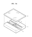
- a method of manufacturing a microfluidic valve 10 according to an embodiment of the present invention will now be described with reference to FIGS. 5A through 5C .
- the method of manufacturing a microfluidic valve 10 described below can also be applied to manufacture a microfluidic device that includes the microfluidic valve 10 according to an embodiment of the present invention.
- FIGS. 5A through 5C are perspective views illustrating a method of manufacturing the microfluidic valve 10 of FIG. 1 , according to an embodiment of the present invention.
- a lower substrate 110 and an upper substrate 120 are prepared.
- a three-dimensional structure that provides the channel and a valve gap forming unit 21 is formed on an upper surface of the lower substrate 110.
- the three-dimensional structure can be an engraved structure.
- the three-dimensional structure is not limited thereto, that is, it can be any structure that can define width and depth of the channel 20 and the valve gap forming unit 21.
- the lower substrate 110 having the above three-dimensional structure can be formed by etching or cutting a flat shape substrate, or can be molded using a mold.
- the flat shape substrate can be employed as the upper substrate 120.
- the upper substrate 120 may have high transmittance with respect to electromagnetic waves, and more preferably, may be optically transparent.
- the upper substrate 120 may not have a hole at least in a region that faces the valve gap forming unit 21. Since a hole is not formed in the upper substrate 120, the molding of the upper substrate 120 is easy and leakage of fluid or pressure loss through the hole can be prevented.
- a predetermined amount of smelted valve material 31 is distributed on the valve gap forming unit 21.
- the amount of the valve material 31 can be determined in consideration of depth and width of the valve gap G and required internal pressure.
- the distribution of the valve material 31 can be performed at room temperature, and the distributed liquid state valve material 31 is solidified.
- the lower substrate 110 and the upper substrate 120 are combined.
- the combining of the lower substrate 110 and the upper substrate 120 can be achieved by various ways, such as using an adhesive or a dual-sided adhesive tape, solvent bonding, ultrasonic welding, or laser welding.
- a method of combining using an adhesive is described.
- An adhesive is coated on the combining unit 115 that includes the outer walls of the channel 20.
- a surface on which the adhesive is coated can be an upper surface of the lower substrate 110 or a lower surface of the upper substrate 120.
- the lower substrate 110 and the upper substrate 120 are pressed together and bonded to form the platform 100.
- electromagnetic waves are radiated onto a region 50A that includes a valve gap using an electromagnetic wave energy source 50 provided from outside of the platform 100.
- the electromagnetic wave energy source 50 can be, for example, a laser source that at least includes one laser diode.
- the laser emitted from the laser source may have energy which does not change a structure in the platform 100 and the characteristics of the valve material, and can be a pulse laser having an output of at least 1 mJ/pulse or more, or alternatively, a continuous wave laser having an output of at least 14 mW or more.
- a laser radiated from the laser source may have a wavelength of 400 to 1300 nm.
- the electromagnetic wave energy source 50 is not limited thereto, and can be an apparatus that can radiate a predetermined wavelength band of one selected from the group consisting of microwaves, infrared rays, visible light, ultraviolet rays, and X rays. Furthermore, an apparatus that can intensively radiate electromagnetic waves on a target a short distance away may be desirable.
- the wavelength of the electromagnetic wave energy source 50 may be in a range that can be readily absorbed by the exothermic particles included in the valve material. Thus, an element that generates electromagnetic waves in the electromagnetic wave energy source can be appropriately selected according to the material and surface conditions of the exothermic particles.
- valve material 31 When the valve material 31 is smelted in the valve gap using the electromagnetic wave energy source 50, the smelted valve material fills the valve gap in a width direction of the valve gap due to a capillary force between the valve gap forming unit 21 and the upper substrate 120. If further electromagnetic wave energy is not applied to the valve material 31, the valve material 31 is re-solidified, and thus, the valve material 31 forms the valve plug 33 to block the flow of fluid.
- a method of locally applying heat onto the region 50A that includes the valve gap so that the valve material 31 can form the valve plug 33 is not limited to the above described method.
- the valve material 31 and the valve gap can be heated by thermal conduction by bringing a heat source such as a thermal plate locally into contact with the region 50A that includes the valve gap.
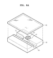
- FIGS. 6A through 6C are perspective views illustrating a method of manufacturing the microfluidic valve of FIG. 3 , according to another embodiment of the present invention.
- an upper substrate 120 and a valve material 31 are prepared.
- a three-dimensional structure that defines a valve material chamber 22 must be prepared.
- the valve material chamber 22 can also be provided by an engraved structure.
- a predetermined amount of smelted valve material 32 is distributed in the valve material chamber 22. This process can be performed at room temperature.
- a combining unit 115 where the two substrates 110 and 120 are combined may include at least the outer walls of the channel 20 and the valve material chamber 22. If the microfluidic valve 11 is employed as a normally open valve, the manufacturing process is at this point complete.
- the microfluidic valve 11 is employed as a normally closed valve, after the combining process, electromagnetic waves are radiated onto the region 50A that includes the valve material chamber 22 using an electromagnetic wave energy source 50 from the outside of the platform 100.
- electromagnetic waves are radiated onto the region 50A that includes the valve material chamber 22 using an electromagnetic wave energy source 50 from the outside of the platform 100.
- the valve material 32 in the valve material chamber 22 is smelted and moves to a gap between the valve gap forming unit 21 and the upper substrate 120, that is, into the valve gap.
- the electromagnetic wave energy can be applied until a portion of the valve material 32 is vaporized in the valve material chamber 22 so that the smelted valve material 32 can be moved to the outside of the valve material chamber 22 due to pressure caused by rapid volume expansion of the valve material 32.
- valve material 32 that fills the valve gap forms a valve plug 34 by re-solidifying when the supply of the electromagnetic wave energy is stopped.
- the method of locally applying heat to the region 50A that includes the valve gap so that the valve material 32 can form the valve plug 34 is not limited thereto.
- the valve material 32 and the valve gap can be heated by thermal conduction by bringing a heat source such as a thermal plate locally into contact with the region 50A that includes the valve gap.
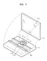
- FIG. 7 is a perspective view illustrating a method of combining the upper substrate 120 and the lower substrate 110 in the course of manufacturing a microfluidic valve according to an embodiment of the present invention.
- a protruding pattern 115P can be formed on a portion that includes the outer walls of the channel 20 and the valve material chamber 22.
- the protruding pattern 115P is formed to have a height greater than the rest areas and a flat surface.
- the protruding pattern 115P can be formed to a band shape along the outer walls of the channel 20 and the valve material chamber 22.
- the height of the protruding pattern 115P defines the width and depth of the channel 20 together with the three-dimensional pattern.
- a flat shape substrate may be employed as the upper substrate 120, or another protruding pattern (not shown) corresponding to the protruding pattern 115P of the lower substrate 110 may be formed on a lower surface of the upper substrate 120.
- an adhesive 115A can be coated on the surface of the protruding pattern 115P.
- the adhesive 115A can be a liquid state adhesive and can be selectively coated on the surface of the protruding pattern 115P using a patterning method such as an inkjet printing method.
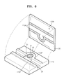
- FIG. 8 is a perspective view illustrating another method of combining an upper substrate and a lower substrate in the course of manufacturing a microfluidic valve according to an embodiment of the present invention.
- a lower substrate 110 having a protruding pattern 115P and an upper substrate 120 having a flat shape are prepared.
- an adhesive 115A is coated on a lower surface of the upper substrate 120 in a shape corresponding to the protruding pattern 115P.
- the adhesive 115A can be a liquid state, and can be coated using a patterning method such as an inkjet printing method. If an inkjet printing method is used, ejected volume of droplets of the liquid state adhesive 115A can be 1 pl to 100 ⁇ l.
- the adhesive 115A can be, for example, an ultraviolet (UV) hardening adhesive. In this case, after coating of the adhesive 115A, the two substrates 110 and 120 are pressed against each other, and UV rays are radiated onto the combined unit.
- UV ultraviolet
- the type of energy that is applied to the combining unit may differ according to the kind of adhesive and method of combining.
- the method of coating the adhesive 115A on a lower surface of the upper substrate 120 prevents the adhesive 115A from entering into the channel 20 leading the reduction of flow channel or from mixing with a reaction solution injected in advance into a chamber (not shown) in the lower substrate 110 in the course of coating the adhesive 115A.
- FIG. 9 is a perspective view of a microfluidic device according to an embodiment of the present invention.
- a microfluidic structure includes a platform 100 having a disc shape, and a plurality of microfluidic valves 10, channels 20, and chambers 41 and 42 included in the platform 100.
- the platform 100 can be rotated, and a fluid can be moved in the microfluidic structure due to the centrifugal force generated by the rotation of the platform 100.
- the platform 100 includes an upper substrate 120 and a lower substrate 110 combined to each other.
- the lower substrate 110 includes three-dimensional structures that provide the chambers 41 and 42 and valve gap forming units 21 and protruding patterns 115P protruding along the outer walls of the microfluidic structure.
- the protruding pattern 115P can be formed in a band shape. However, it is unnecessary for the protruding pattern 115P to have a uniform width or a band shape.
- sample chambers 41 the chambers 41 close to the center of the platform 100 is referred to as sample chambers 41, and sample injection holes 41A connected to the sample chambers 41 can be formed in the upper substrate 120.
- an upper substrate 120 and a lower substrate 110 as described above are prepared, a valve material 31 is distributed in the valve gap forming unit 21 on the lower substrate 110, and a reaction solution is injected into the reaction chamber 42.
- a reaction solution is injected into the reaction chamber 42.
- an adhesive pattern corresponding to the protruding pattern 115P on the lower substrate 110 is formed on the lower surface of the upper substrate 120.
- the two substrates 120 and 110 are overlapped and pressed against each other.
- manufacture of the platform 100 described above can be completed.
- a microfluidic device can be manufactured through smelting and solidifying the valve material 31 by radiating electromagnetic wave energy to the microfluidic valve 10.
Landscapes
- Engineering & Computer Science (AREA)
- General Engineering & Computer Science (AREA)
- Chemical & Material Sciences (AREA)
- Dispersion Chemistry (AREA)
- Mechanical Engineering (AREA)
- Health & Medical Sciences (AREA)
- Toxicology (AREA)
- Micromachines (AREA)
- Electrically Driven Valve-Operating Means (AREA)
Applications Claiming Priority (2)
| Application Number | Priority Date | Filing Date | Title |
|---|---|---|---|
| KR1020070061128A KR101473871B1 (ko) | 2007-06-21 | 2007-06-21 | 미세유체 제어용 밸브 유닛의 제조방법, 미세유체 제어용밸브 유닛 및, 상기 밸브 유닛을 구비한 미세유동 장치 |
| KR1020070079175A KR101391736B1 (ko) | 2007-08-07 | 2007-08-07 | 미세유동 밸브, 상기 미세유동 밸브의 제조 방법 및 상기미세유동 밸브를 포함하는 미세유동 장치 |
Publications (2)
| Publication Number | Publication Date |
|---|---|
| EP2006588A2 true EP2006588A2 (fr) | 2008-12-24 |
| EP2006588A3 EP2006588A3 (fr) | 2010-09-01 |
Family
ID=39766877
Family Applications (1)
| Application Number | Title | Priority Date | Filing Date |
|---|---|---|---|
| EP20080158046 Withdrawn EP2006588A3 (fr) | 2007-06-21 | 2008-06-11 | Soupape microfluidique, son procédé de fabrication et dispositif microfluidique comprenant la soupape microfluidique |
Country Status (2)
| Country | Link |
|---|---|
| US (2) | US7980272B2 (fr) |
| EP (1) | EP2006588A3 (fr) |
Cited By (1)
| Publication number | Priority date | Publication date | Assignee | Title |
|---|---|---|---|---|
| GB2548967A (en) * | 2016-02-18 | 2017-10-04 | Leica Biosystems Nussloch Gmbh | Inductive melting of paraffin by means of metallic bodies contained therein |
Families Citing this family (26)
| Publication number | Priority date | Publication date | Assignee | Title |
|---|---|---|---|---|
| US8172375B2 (en) * | 2004-12-17 | 2012-05-08 | Brother Kogyo Kabushiki Kaisha | Valve and actuator employing capillary electrowetting phenomenon |
| KR100668335B1 (ko) * | 2005-04-02 | 2007-01-12 | 삼성전자주식회사 | 자성 왁스 플러그를 구비한 마이크로 밸브 및 자성 왁스를이용한 유동 제어 방법 |
| KR101578149B1 (ko) * | 2009-01-29 | 2015-12-17 | 삼성전자주식회사 | 미세유체 제어용 밸브 유닛, 및 이의 제조방법 |
| KR101130698B1 (ko) * | 2009-11-03 | 2012-04-02 | 삼성전자주식회사 | 밸브 유닛과 이를 구비한 미세유동장치 및 밸브 유닛의 구동방법 |
| DE102010028012A1 (de) | 2010-04-21 | 2011-10-27 | Qiagen Gmbh | Flüssigkeitssteuerung für Mikrodurchflusssystem |
| DE102013205412A1 (de) * | 2013-03-27 | 2014-10-02 | Robert Bosch Gmbh | Normal-geschlossenes Ventil für mikrofluidische Bauteile aus einem polymeren Schichtsystem sowie Verfahren |
| KR20140142624A (ko) * | 2013-06-04 | 2014-12-12 | 삼성전자주식회사 | 미세유동장치 |
| KR102176587B1 (ko) | 2013-10-15 | 2020-11-10 | 삼성전자주식회사 | 시료분석장치, 시료분석방법, 및 밸브의 동적 작동 방법 |
| US9995411B1 (en) * | 2014-07-16 | 2018-06-12 | National Technology & Engineering Solutions Of Sandia, Llc | High-temperature, adhesive-based microvalves and uses thereof |
| DE102014216395A1 (de) | 2014-08-19 | 2016-02-25 | Robert Bosch Gmbh | Blockadefreie Öffnung zu vorgelagerten Substanzen |
| DE102014216391A1 (de) | 2014-08-19 | 2016-02-25 | Robert Bosch Gmbh | Reagenzienvorlagerung mit definierter Entnahme |
| GB201615452D0 (en) * | 2016-09-12 | 2016-10-26 | Fluidic Analytics Ltd | Improvements in or relating to valves for microfluidics devices |
| EP3348886B1 (fr) * | 2017-01-13 | 2019-11-27 | Consejo Superior De Investigaciones Cientificas | Soupape microfluidique |
| US11717825B2 (en) | 2017-12-28 | 2023-08-08 | Stmicroelectronics S.R.L. | Magnetically controllable valve and portable microfluidic device having a magnetically controllable valve, in particular cartridge for sample preparation and molecule analysis |
| US11511278B2 (en) | 2017-12-28 | 2022-11-29 | Stmicroelectronics S.R.L. | Solid reagent containment unit, in particular for a portable microfluidic device for sample preparation and molecule analysis |
| US11491489B2 (en) | 2017-12-28 | 2022-11-08 | Stmicroelectronics S.R.L. | Microfluidic connector group, microfluidic device and manufacturing process thereof, in particular for a cartridge for sample preparation and molecule analysis |
| US11278897B2 (en) | 2017-12-28 | 2022-03-22 | Stmicroelectronics S.R.L. | Cartridge for sample preparation and molecule analysis, cartridge control machine, sample preparation system and method using the cartridge |
| US11110457B2 (en) | 2017-12-28 | 2021-09-07 | Stmicroelectronics S.R.L. | Analysis unit for a transportable microfluidic device, in particular for sample preparation and molecule analysis |
| WO2019187294A1 (fr) * | 2018-03-30 | 2019-10-03 | 富士フイルム株式会社 | Embout, dispositif et procédé de mélange |
| CN108591610B (zh) * | 2018-04-27 | 2024-04-23 | 湖南乐准智芯生物科技有限公司 | 一种微流控系统及微阀、控制方法 |
| US10746248B2 (en) * | 2018-07-25 | 2020-08-18 | Tenneco Automotive Operating Company Inc. | Valve assembly |
| CN108843855B (zh) * | 2018-08-31 | 2024-03-12 | 湖南乐准智芯生物科技有限公司 | 一种微流控系统及常闭微阀、控制方法 |
| CN109603929B (zh) * | 2018-11-09 | 2021-01-05 | 哈尔滨工业大学(深圳) | 芯片上阀门的制造方法、微流控芯片与液体流动控制方法 |
| CN110886901B (zh) * | 2019-11-20 | 2021-06-08 | 东莞市东阳光诊断产品有限公司 | 基板、相变阀及其控制方法 |
| US12103000B2 (en) * | 2020-04-10 | 2024-10-01 | The Regents Of The University Of California | Microfluidic phase-change membrane microvalves |
| CN114634869A (zh) * | 2022-03-21 | 2022-06-17 | 诺美纳瑞(广州)医疗技术有限公司 | 一种pcr的检测系统 |
Citations (2)
| Publication number | Priority date | Publication date | Assignee | Title |
|---|---|---|---|---|
| US20060180223A1 (en) | 2003-06-16 | 2006-08-17 | Biomerieux | Electrically opended micro fluid-valve |
| WO2006104467A1 (fr) | 2005-03-31 | 2006-10-05 | Agency For Science, Technology And Research | Dispositif microfluidique configurable et procede associe |
Family Cites Families (70)
| Publication number | Priority date | Publication date | Assignee | Title |
|---|---|---|---|---|
| US3465774A (en) * | 1967-03-10 | 1969-09-09 | Aro Corp | Semi-integrated (fluidic) logic system |
| US3516537A (en) * | 1968-06-27 | 1970-06-23 | Grace W R & Co | Opening device on bags and the like |
| US4064296A (en) * | 1975-10-02 | 1977-12-20 | W. R. Grace & Co. | Heat shrinkable multi-layer film of hydrolyzed ethylene vinyl acetate and a cross-linked olefin polymer |
| US4113139A (en) * | 1977-05-12 | 1978-09-12 | W. R. Grace & Co. | Sealed taped bags and sealed tape bag dispenser |
| US4278738A (en) * | 1978-03-10 | 1981-07-14 | W. R. Grace & Co. | Ethylene-vinyl acetate copolymer film laminate |
| US4755403A (en) * | 1985-06-03 | 1988-07-05 | W. R. Grace & Co., Cryovac Div. | Protective patch for shrinkable bag |
| US4958735A (en) * | 1985-06-28 | 1990-09-25 | W. R. Grace & Co.-Conn. | Easy open, hemetically sealed, display package made from heat shrinkable film |
| US4768411A (en) * | 1986-11-07 | 1988-09-06 | W. R. Grace & Co., Cryovac Div. | Easy-open bag and apparatus and method for making same |
| US4778058A (en) * | 1987-03-19 | 1988-10-18 | Kabushiki Kaisha Hosokawa Yoko | Pouch or sack for packing and laminate film therefor and method for producing the pouch |
| US4861414A (en) * | 1987-10-16 | 1989-08-29 | W. R. Grace & Co. | Easy-open flexible pouch and apparatus and method for making same |
| JP2845324B2 (ja) * | 1988-10-13 | 1999-01-13 | 株式会社興人 | 二軸延伸ポリアミド系フィルム及びその製造方法 |
| US5127065A (en) * | 1990-04-17 | 1992-06-30 | Wade Steven E | Opening device for flexible packaging |
| US5308668A (en) * | 1990-05-14 | 1994-05-03 | Kuriron Kasei Ltd. | Multilayer film made of synthetic resin |
| NO302409B1 (no) * | 1991-10-11 | 1998-03-02 | Sodap | Lett rivbar pakning |
| US5562958A (en) * | 1991-10-15 | 1996-10-08 | The Dow Chemical Company | Packaging and wrapping film |
| US6221410B1 (en) * | 1992-09-25 | 2001-04-24 | Cryovac, Inc. | Backseamed casing and packaged product incorporating same |
| DE69323877T2 (de) * | 1992-11-06 | 1999-07-29 | Daicel Chemical Industries, Ltd., Sakai, Osaka | Leicht reissbare folie und deren herstellungsverfahren |
| US5413412A (en) * | 1993-02-24 | 1995-05-09 | W.R. Grace & Co.-Conn. | Easy open bag |
| CA2104719C (fr) * | 1993-04-21 | 2005-12-27 | W.R. Grace & Co.-Conn. | Methode de fabrication d'un sac thermoretractable muni d'une piece de protection |
| BR9508136A (pt) * | 1994-06-28 | 1997-11-25 | Grace W R & Co | Bolsas tendo remendos protetores |
| US5545419A (en) * | 1994-07-21 | 1996-08-13 | W. R. Grace & Co.-Conn. | Patch bag having supplemental seal |
| US5806280A (en) * | 1995-06-16 | 1998-09-15 | W. R. Grace & Co.-Conn. | Easy open method, package, and apparatus |
| EP0812874B1 (fr) * | 1995-12-28 | 2004-06-30 | Gunze Limited | Film pouvant etre facilement rompu |
| US5689935A (en) * | 1996-03-11 | 1997-11-25 | Recot, Inc. | Product package having reliable openability |
| JPH1039453A (ja) * | 1996-07-18 | 1998-02-13 | Fuji Photo Film Co Ltd | 易開封性感光材料包装体及びその製造方法 |
| US6780373B1 (en) * | 1996-12-20 | 2004-08-24 | Cryovac, Inc. | Method of making an easy open tear film |
| US6296886B1 (en) * | 1997-03-17 | 2001-10-02 | Cryovac, Inc. | Method of film crease elimination and patch bag without crease within lay-flat bag side |
| WO1998053311A2 (fr) * | 1997-05-23 | 1998-11-26 | Gamera Bioscience Corporation | Dispositifs et procedes permettant d'utiliser l'acceleration centripete pour commander le deplacement de fluides sur un systeme microfluidique |
| JP3227413B2 (ja) * | 1997-09-19 | 2001-11-12 | 出光石油化学株式会社 | 易裂性シュリンクラミネートフィルム及びこれを使用した袋製品 |
| US6270819B1 (en) * | 1997-09-23 | 2001-08-07 | Cryovac, Inc. | Patch bag having curved seal and curved patch |
| US6790468B1 (en) * | 1997-09-30 | 2004-09-14 | Cryovac, Inc. | Patch bag and process of making same |
| US6663905B1 (en) * | 1998-03-16 | 2003-12-16 | Cryovac, Inc. | Patch bag having wrap-around patch |
| ES2213365T3 (es) * | 1998-04-16 | 2004-08-16 | Cryovac, Inc. | Mezcla de polimero ternario, elemento laminar que lo contiene y embalaje de apertura facil fabricado con el mismo. |
| US6749785B2 (en) * | 1998-09-01 | 2004-06-15 | E. I. Du Pont De Nemours And Company | Multilayer structures of poly(1,3-propylene 2,6 napthalate) and poly (ethylene terephthalate) |
| US6260705B1 (en) * | 1999-11-15 | 2001-07-17 | Cryovac, Inc. | Heat shrinkable pouch |
| US6479137B1 (en) * | 2000-05-09 | 2002-11-12 | Exxon Mobil Oil Corporation | Controlled directional tear laminates |
| US7384679B2 (en) * | 2000-08-29 | 2008-06-10 | Pechiney Emballage Flexible Europe | Encapsulated barrier for flexible films and a method of making and using the same |
| US6382254B1 (en) * | 2000-12-12 | 2002-05-07 | Eastman Kodak Company | Microfluidic valve and method for controlling the flow of a liquid |
| GB0100352D0 (en) * | 2001-01-08 | 2001-02-14 | Ucb Sa | Films packaging and methods for making them |
| US6575188B2 (en) * | 2001-07-26 | 2003-06-10 | Handylab, Inc. | Methods and systems for fluid control in microfluidic devices |
| US20030156991A1 (en) * | 2001-10-23 | 2003-08-21 | William Marsh Rice University | Optomechanically-responsive materials for use as light-activated actuators and valves |
| GB0204602D0 (en) * | 2002-02-27 | 2002-04-10 | Ucb Sa | Packaging methods and packs made thereby |
| US6679279B1 (en) * | 2002-07-10 | 2004-01-20 | Motorola, Inc. | Fluidic valve having a bi-phase valve element |
| US6979494B2 (en) * | 2002-08-27 | 2005-12-27 | Cryovac, Inc. | Dual-ovenable, heat-sealable packaging film |
| ITPD20020310A1 (it) * | 2002-12-05 | 2004-06-06 | Bp Europack Spa | Film lacerabile in materia plastica particolarmente |
| US7048125B2 (en) * | 2002-12-19 | 2006-05-23 | Cryovac, Inc. | Patch bag having patch covering seal |
| US20040166261A1 (en) * | 2003-02-20 | 2004-08-26 | Pockat Gregory Robert | Heat-shrinkable packaging receptacle |
| WO2004073983A1 (fr) * | 2003-02-24 | 2004-09-02 | Mitsubishi Polyester Film Corporation | Film de polyester stratifie a orientation biaxiale et film de polyester pour materiau de couvercle |
| US20040175465A1 (en) * | 2003-03-07 | 2004-09-09 | Buelow Duane H. | Thermoplastic multilayer structures |
| US20040175466A1 (en) * | 2003-03-07 | 2004-09-09 | Douglas Michael J. | Multilayer barrier structures, methods of making the same and packages made therefrom |
| US20040175467A1 (en) * | 2003-03-07 | 2004-09-09 | Mueller Chad D. | Packages made from multilayer structures |
| US20040175592A1 (en) * | 2003-03-07 | 2004-09-09 | Douglas Michael J. | Thermoplastic multilayer barrier structures |
| US20040175464A1 (en) * | 2003-03-07 | 2004-09-09 | Blemberg Robert J. | Multilayer structures, packages, and methods of making multilayer structures |
| US7374045B2 (en) * | 2003-03-26 | 2008-05-20 | Diliberto Samuel L | Disaster pack and method for making the same |
| US6708826B1 (en) * | 2003-04-30 | 2004-03-23 | Warner-Lambert Company, Llc | Packaged supply of individual doses of a personal care product |
| US20060134287A1 (en) * | 2003-08-20 | 2006-06-22 | Vimini Robert J | Packaging and cooking bag and method for packaging and preparing a meat product |
| US20050058793A1 (en) * | 2003-09-17 | 2005-03-17 | Schaefer Suzanne E. | Multilayer heat sealant structures, packages and methods of making the same |
| AR053693A1 (es) * | 2004-03-17 | 2007-05-16 | Dow Global Technologies Inc | Composiciones de interpolimero de etileno/alfa-olefina multibloque adecuado para peliculas |
| KR100668335B1 (ko) * | 2005-04-02 | 2007-01-12 | 삼성전자주식회사 | 자성 왁스 플러그를 구비한 마이크로 밸브 및 자성 왁스를이용한 유동 제어 방법 |
| US20070092409A1 (en) * | 2005-10-21 | 2007-04-26 | Beatty Christopher C | Reconfigurable valve using optically active material |
| EP1984277A1 (fr) * | 2006-01-31 | 2008-10-29 | Cryovac, Inc. | Recipient flexible, facilement ouvrable, hermetiquement ferme fait d'un materiau thermoplastique thermoretractable |
| US8464760B2 (en) * | 2006-08-16 | 2013-06-18 | Samsung Electronic Co., Ltd. | Valve unit, reaction apparatus with the same, and method of forming valve in channel |
| KR100846501B1 (ko) * | 2006-11-09 | 2008-07-17 | 삼성전자주식회사 | 밸브 유닛 및 이를 구비한 유체 처리 장치 |
| US20080182051A1 (en) * | 2007-01-29 | 2008-07-31 | Cryovac, Inc. | Heat shrinkable retortable packaging article and process for preparing retorted packaged product |
| US20080182052A1 (en) * | 2007-01-29 | 2008-07-31 | Cryovac, Inc. | Multilayer heat-shrinkable film of high transparency, low haze, and high semi-crystalline polyamide content |
| US7687123B2 (en) * | 2007-01-29 | 2010-03-30 | Cryovac, Inc. | Shrink film containing semi-crystalline polyamide and process for making same |
| US7744806B2 (en) * | 2007-01-29 | 2010-06-29 | Cryovac, Inc. | Process for making shrink film comprising rapidly-quenched semi-crystalline polyamide |
| KR20080073934A (ko) * | 2007-02-07 | 2008-08-12 | 삼성전자주식회사 | 밸브 충전물 및 이를 구비한 밸브 유닛 |
| KR101335727B1 (ko) * | 2007-08-22 | 2013-12-04 | 삼성전자주식회사 | 원심력 기반의 혈액 검사용 디스크형 미세유동장치 |
| KR101578149B1 (ko) * | 2009-01-29 | 2015-12-17 | 삼성전자주식회사 | 미세유체 제어용 밸브 유닛, 및 이의 제조방법 |
-
2008
- 2008-06-05 US US12/133,396 patent/US7980272B2/en active Active
- 2008-06-11 EP EP20080158046 patent/EP2006588A3/fr not_active Withdrawn
-
2011
- 2011-06-10 US US13/157,535 patent/US20110232832A1/en not_active Abandoned
Patent Citations (2)
| Publication number | Priority date | Publication date | Assignee | Title |
|---|---|---|---|---|
| US20060180223A1 (en) | 2003-06-16 | 2006-08-17 | Biomerieux | Electrically opended micro fluid-valve |
| WO2006104467A1 (fr) | 2005-03-31 | 2006-10-05 | Agency For Science, Technology And Research | Dispositif microfluidique configurable et procede associe |
Cited By (2)
| Publication number | Priority date | Publication date | Assignee | Title |
|---|---|---|---|---|
| GB2548967A (en) * | 2016-02-18 | 2017-10-04 | Leica Biosystems Nussloch Gmbh | Inductive melting of paraffin by means of metallic bodies contained therein |
| GB2548967B (en) * | 2016-02-18 | 2020-01-22 | Leica Biosystems Nussloch Gmbh | Inductive melting of paraffin by means of metallic bodies contained therein |
Also Published As
| Publication number | Publication date |
|---|---|
| US20080314465A1 (en) | 2008-12-25 |
| EP2006588A3 (fr) | 2010-09-01 |
| US7980272B2 (en) | 2011-07-19 |
| US20110232832A1 (en) | 2011-09-29 |
Similar Documents
| Publication | Publication Date | Title |
|---|---|---|
| US7980272B2 (en) | Microfluidic valve, method of manufacturing the same, and microfluidic device comprising the microfluidic valve | |
| EP1920843B1 (fr) | Unité de soupape, dispositif microfluide avec l'unité de soupape, et substrat microfluide | |
| KR101130698B1 (ko) | 밸브 유닛과 이를 구비한 미세유동장치 및 밸브 유닛의 구동방법 | |
| KR101258434B1 (ko) | 미세유동 시스템 및,이의 제조방법 | |
| KR101578149B1 (ko) | 미세유체 제어용 밸브 유닛, 및 이의 제조방법 | |
| US7926514B2 (en) | Valve unit and reaction apparatus having the same | |
| US8105551B2 (en) | Microfluidic device and method of fabricating the same | |
| JP5174481B2 (ja) | 希釈のための遠心力基盤の微細流動装置及びそれを備える微細流動システム | |
| US8119079B2 (en) | Microfluidic apparatus having fluid container | |
| EP2420319A1 (fr) | Dispositif microfluidique centrifuge doté d'une structure de distribution d'échantillons et système microfluidique centrifuge doté du dispositif microfluidique centrifuge | |
| CN101126465B (zh) | 阀单元,具有该阀单元的反应装置以及在通道中形成阀的方法 | |
| KR101391736B1 (ko) | 미세유동 밸브, 상기 미세유동 밸브의 제조 방법 및 상기미세유동 밸브를 포함하는 미세유동 장치 | |
| KR101473871B1 (ko) | 미세유체 제어용 밸브 유닛의 제조방법, 미세유체 제어용밸브 유닛 및, 상기 밸브 유닛을 구비한 미세유동 장치 | |
| KR100955481B1 (ko) | 밸브 유닛, 이를 구비한 미세유동장치, 및 상기 밸브유닛의 제조방법 | |
| KR100763923B1 (ko) | 폐쇄밸브 유닛 및 이를 구비한 반응장치 |
Legal Events
| Date | Code | Title | Description |
|---|---|---|---|
| PUAI | Public reference made under article 153(3) epc to a published international application that has entered the european phase |
Free format text: ORIGINAL CODE: 0009012 |
|
| AK | Designated contracting states |
Kind code of ref document: A2 Designated state(s): AT BE BG CH CY CZ DE DK EE ES FI FR GB GR HR HU IE IS IT LI LT LU LV MC MT NL NO PL PT RO SE SI SK TR |
|
| AX | Request for extension of the european patent |
Extension state: AL BA MK RS |
|
| PUAL | Search report despatched |
Free format text: ORIGINAL CODE: 0009013 |
|
| AK | Designated contracting states |
Kind code of ref document: A3 Designated state(s): AT BE BG CH CY CZ DE DK EE ES FI FR GB GR HR HU IE IS IT LI LT LU LV MC MT NL NO PL PT RO SE SI SK TR |
|
| AX | Request for extension of the european patent |
Extension state: AL BA MK RS |
|
| 17P | Request for examination filed |
Effective date: 20110228 |
|
| AKX | Designation fees paid |
Designated state(s): DE ES FR GB IT SE |
|
| RAP1 | Party data changed (applicant data changed or rights of an application transferred) |
Owner name: SAMSUNG ELECTRONICS CO., LTD. |
|
| 17Q | First examination report despatched |
Effective date: 20151221 |
|
| STAA | Information on the status of an ep patent application or granted ep patent |
Free format text: STATUS: THE APPLICATION IS DEEMED TO BE WITHDRAWN |
|
| 18D | Application deemed to be withdrawn |
Effective date: 20160503 |