EP2006616A2 - Eléments de refroidissement de sorption flexibles - Google Patents
Eléments de refroidissement de sorption flexibles Download PDFInfo
- Publication number
- EP2006616A2 EP2006616A2 EP08008007A EP08008007A EP2006616A2 EP 2006616 A2 EP2006616 A2 EP 2006616A2 EP 08008007 A EP08008007 A EP 08008007A EP 08008007 A EP08008007 A EP 08008007A EP 2006616 A2 EP2006616 A2 EP 2006616A2
- Authority
- EP
- European Patent Office
- Prior art keywords
- cooling element
- sorbent
- working fluid
- element according
- bag
- Prior art date
- Legal status (The legal status is an assumption and is not a legal conclusion. Google has not performed a legal analysis and makes no representation as to the accuracy of the status listed.)
- Withdrawn
Links
Images


Classifications
-
- F—MECHANICAL ENGINEERING; LIGHTING; HEATING; WEAPONS; BLASTING
- F25—REFRIGERATION OR COOLING; COMBINED HEATING AND REFRIGERATION SYSTEMS; HEAT PUMP SYSTEMS; MANUFACTURE OR STORAGE OF ICE; LIQUEFACTION SOLIDIFICATION OF GASES
- F25B—REFRIGERATION MACHINES, PLANTS OR SYSTEMS; COMBINED HEATING AND REFRIGERATION SYSTEMS; HEAT PUMP SYSTEMS
- F25B17/00—Sorption machines, plants or systems, operating intermittently, e.g. absorption or adsorption type
- F25B17/08—Sorption machines, plants or systems, operating intermittently, e.g. absorption or adsorption type the absorbent or adsorbent being a solid, e.g. salt
-
- F—MECHANICAL ENGINEERING; LIGHTING; HEATING; WEAPONS; BLASTING
- F25—REFRIGERATION OR COOLING; COMBINED HEATING AND REFRIGERATION SYSTEMS; HEAT PUMP SYSTEMS; MANUFACTURE OR STORAGE OF ICE; LIQUEFACTION SOLIDIFICATION OF GASES
- F25D—REFRIGERATORS; COLD ROOMS; ICE-BOXES; COOLING OR FREEZING APPARATUS NOT OTHERWISE PROVIDED FOR
- F25D31/00—Other cooling or freezing apparatus
- F25D31/006—Other cooling or freezing apparatus specially adapted for cooling receptacles, e.g. tanks
- F25D31/007—Bottles or cans
-
- F—MECHANICAL ENGINEERING; LIGHTING; HEATING; WEAPONS; BLASTING
- F25—REFRIGERATION OR COOLING; COMBINED HEATING AND REFRIGERATION SYSTEMS; HEAT PUMP SYSTEMS; MANUFACTURE OR STORAGE OF ICE; LIQUEFACTION SOLIDIFICATION OF GASES
- F25D—REFRIGERATORS; COLD ROOMS; ICE-BOXES; COOLING OR FREEZING APPARATUS NOT OTHERWISE PROVIDED FOR
- F25D2331/00—Details or arrangements of other cooling or freezing apparatus not provided for in other groups of this subclass
- F25D2331/80—Type of cooled receptacles
- F25D2331/803—Bottles
-
- F—MECHANICAL ENGINEERING; LIGHTING; HEATING; WEAPONS; BLASTING
- F25—REFRIGERATION OR COOLING; COMBINED HEATING AND REFRIGERATION SYSTEMS; HEAT PUMP SYSTEMS; MANUFACTURE OR STORAGE OF ICE; LIQUEFACTION SOLIDIFICATION OF GASES
- F25D—REFRIGERATORS; COLD ROOMS; ICE-BOXES; COOLING OR FREEZING APPARATUS NOT OTHERWISE PROVIDED FOR
- F25D2500/00—Problems to be solved
- F25D2500/02—Geometry problems
-
- Y—GENERAL TAGGING OF NEW TECHNOLOGICAL DEVELOPMENTS; GENERAL TAGGING OF CROSS-SECTIONAL TECHNOLOGIES SPANNING OVER SEVERAL SECTIONS OF THE IPC; TECHNICAL SUBJECTS COVERED BY FORMER USPC CROSS-REFERENCE ART COLLECTIONS [XRACs] AND DIGESTS
- Y10—TECHNICAL SUBJECTS COVERED BY FORMER USPC
- Y10T—TECHNICAL SUBJECTS COVERED BY FORMER US CLASSIFICATION
- Y10T29/00—Metal working
- Y10T29/49—Method of mechanical manufacture
- Y10T29/4935—Heat exchanger or boiler making
- Y10T29/49359—Cooling apparatus making, e.g., air conditioner, refrigerator
Definitions
- the invention relates to sorption cooling elements with a gas-tight film for cooling of containers in which is produced by evaporation of a working fluid and sorption of the working medium vapor in a sorbent under vacuum cold and method for producing and starting these cooling elements.
- Adsorption devices are devices in which a solid adsorbent sorbs a second, boiling at lower temperatures, the vaporous working medium, under heat release (sorption).
- the working fluid evaporates in an evaporator while absorbing heat. After the sorbent is saturated, it can be desorbed by supplying heat at a higher temperature (desorption phase). During this process, working fluid evaporates from the adsorbent. The working fluid vapor can be reliquefied and then re-vaporized.
- Absorption devices are apparatus in which a liquid absorbent is used. The term "sorption devices" includes both adsorption and absorption systems.
- Adsorption apparatus for cooling with solid sorbents are from EP 0 368 111 and the DE-OS 34 25 419 known. Sorbent container, filled with sorbents, thereby absorb working agent vapor, which is produced in an evaporator, and sorb it under heat release. This sorption heat must be removed from the sorbent.
- the chillers can be used to cool and keep food warm in thermally insulated boxes.
- the WO 01/10738 A1 describes a self-cooling beverage can with an evaporator inside and a sorber outside the can.
- the cooling is started by opening a steam channel between evaporator and sorber.
- the cold generated in the evaporator is discharged through the surfaces of the drink to be cooled within the can.
- the heat generated in the sorbent is stored in a heat buffer.
- the self-cooling beverage can is heavily modified over an ordinary can and expensive to manufacture.
- the US Pat. No. 6,474,100 B1 finally describes a self-cooling cooling element on the outside of a bag for liquids or bulk materials.
- the sorbent is enclosed in a flexible, multi-layered film.
- the contact with the hot sorption filling is minimized by insulation and flow materials as well as by intervening heat storage masses.
- the temperature compensation between the hot sorber filling and the cold evaporator, which are opposed over a large area, must be reduced by an elaborate insulation.
- the object of the invention are cost-effective, flexible sorption cooling elements, and methods for their preparation.
- the sorbent and the evaporator are surrounded by a multilayer film.
- the evaporator contains a nonwoven and a flexible, vapor-permeable structural material, which together have a flat but flexible geometry under vacuum, which can be easily pressed against any containers to be cooled.
- the structural material directs after the start of the cooling element, the working medium vapor to the sorbent and leaves for the working medium vapor, a flow cross-section of at least 1 cm 2 open.
- a flexible design of the evaporator which can be optimally adapted in particular cylindrical geometries, and on the other hand, the necessary flow channel from the evaporator to the sorbent can be realized in the required cross-section.
- the flow cross-section In order to achieve a sufficiently rapid cooling, the flow cross-section must have at least an area of 1 square centimeter (cm 2 ). With water as a working medium, a cooling capacity of over 20 watts can be generated.
- the multi-layer film required for the gastight vacuum envelope encloses all components necessary for operation and storage time. It can be manufactured in one piece if required and allows the necessary freedom of movement under vacuum to the internal flexible components. With an aluminum barrier layer in the multilayer film Shelf life of more than one year is possible without too much gas being diffused through the film during storage.
- the evaporator surface of the cooling element is pressed onto the outer surface of the container according to the invention.
- the evaporator is designed to be flexible and pressed the cold evaporator surface by means of separate, elastic pressing means surface on the outer surface of the liquid container to use a large part of the sometimes highly structured surface of the container for heat exchange.
- pressing means are, for example, adhesive tapes, stretch or shrink films and rubber bands or hook and loop fasteners of any kind.
- the liquid container can remain partially visible and the pouring of the liquid cooling element does not need to be opened or removed.
- the container As a container all common vessels such as bottles, cans, barrels, bags, cans, cardboard packaging, etc. understood that serve to hold liquids such as drinks, medicines but also chemical products. Of course, the container may also contain solid or free-flowing products. Basically, the container must not be changed compared to its usual shape and features. Thus, all previously used manufacturing and filling devices can be used unchanged.
- the evaporator can take any shape and be made of any materials.
- a vapor-permeable structural material is provided which allows the working medium vapor to flow away unhindered from the liquid working medium and, at the same time, allows its flexibility to contact the cold evaporator regions in good heat-conducting with the outer multilayer film.
- plastic flexible structural materials can be used for this, which are adapted to the respective cooling task.
- the prerequisite is, however, that the structural materials do not outgas during the storage time and thereby impair the vacuum.
- polycarbonate or polypropylene are used as the plastic, since these materials were heated to higher temperatures before and during the manufacturing process and thereby degassed.
- Plastic structural materials can be inexpensively manufactured by the usual manufacturing techniques such as deep drawing, extruding or blowing.
- Extruded meshes and meshes made of polypropylene which are used in one or more layers, have proven to be particularly effective, on the one hand providing the necessary flexibility with respect to deformation and, on the other hand, the rigidity with respect to the air pressure applied externally via the multilayer film.
- Particularly suitable polypropylene structural materials are sold by Tenax Germany.
- the product OS 102 is a diamond-shaped grid that leaves ideal geometries for the working medium vapor flowing in the lattice plane open and supports the externally applied multi-layer foil. Two- and multi-layer layers of this grid can be used particularly advantageous as a structural material.
- Sorbents can reach temperatures of over 100 ° C during the sorption process. For such high temperatures, the multi-layer films commonly used in the packaging sector are less suitable. In particular, the polyethylene layers frequently used for sealing become soft even at 80 ° C. and cause the sheath to leak under vacuum. Polypropylene sealing layers, on the other hand, can withstand significantly higher temperatures. Its melting point is above 150 ° C. In combination with high temperatures, sharp edges, corners and tips of sorbent granules create impermissible leaks. This risk can be counteracted according to the invention by polyamide and / or polyester sheaths within the multilayer film. Polyester and polyamide films are particularly tear and puncture resistant. The actual gas barrier is ensured by a layer of thin metal foils or metallized layers.
- Thin aluminum foils with a layer thickness of approx. 8 ⁇ m have proven to be suitable for this purpose. Less dense are metallized plastic films. Nevertheless, with short storage periods, the use of these metallized films is possible, especially as they face the metal foils are cheaper to produce.
- the individual layers of a multilayer film are bonded together by adhesive.
- Commercially available adhesives contain solvents which are not completely removed from the adhesive layer during bonding. Over long periods of time, these solvents then diffuse through the internal layers, particularly the polyethylene layer, and affect the vacuum within the cooling element. The diffusion is enhanced at higher temperatures, such as occur in the sorption and manufacturing process of the cooling elements.
- the adhesive used must therefore also be designed for high temperatures and vacuum.
- multi-layer films with polyester or polyamide layer thicknesses of 12 to 50 ⁇ m, an aluminum layer thickness of 8 ⁇ m and a polypropylene layer thickness of 50 to 100 ⁇ m are used. Use find such films z.
- packaging of foods that are sterilized after packaging for preserving at temperatures above 120 ° C.
- the sorbent used is advantageously zeolite. In its regular crystal structure, this can reversibly absorb up to 36% by mass of water. In the application according to the invention, the technically feasible water absorption is 20 to 25%. Zeolites still have a considerable water vapor sorption capacity even at relatively high temperatures (above 100 ° C.) and are therefore particularly suitable for the use according to the invention.
- Zeolite is a crystalline mineral that consists of a regular skeletal structure of silicon and aluminum oxides. This framework structure contains cavities in which water molecules can be sorbed by releasing heat. Within the framework structure, the water molecules are exposed to strong field forces whose strength depends on the amount of water already contained in the framework structure and the temperature of the zeolite. Naturally occurring natural zeolite types absorb significantly less water.
- Natural zeolites have another advantage.
- the non-active Admixtures are typically 10 to 30%. They are not actively involved in refrigeration, but they are heated by the neighboring zeolite crystals. They thus act as an additionally installed, inexpensive heat buffer. The result is that the zeolite filling is less hot and thus can sorb additional water vapor at lower temperatures.
- Natural zeolite granules consist of broken or crushed fragments and therefore have sharp and pointed geometric shapes that can puncture or cut through the envelope under vacuum and elevated temperatures.
- zeolites For zeolites, there is still a risk that, depending on the synthesis process, occurrence and degradation processes, they contain admixtures which emit gaseous constituents in a vacuum, and in particular at elevated temperatures, which influence the cooling process.
- This problem of gas release is solved by the fact that zeolites are heated at least to the later sorbent temperature before production of the cooling element and at the same time placed under the then prevailing vacuum. In this procedure, zeolites can release their interfering constituents according to the invention. This thermal treatment is particularly efficient if at the same time the presorbed water can be evaporated off.
- gas-tight multilayer films having an inner polypropylene layer and at least one polyester layer are used according to the invention. These can also be filled with hot sorbents.
- clinoptilolites chabazites, mordenites and phillipsites. They occur frequently, are inexpensive to process and have a sufficiently rapid sorption characteristic.
- Natural zeolites can after their use in cooling elements z. B. be used as soil conditioner, as a liquid binder or to improve the quality of water in ponds and waters.
- the types A, X and Y are used, each in their low-cost Na form.
- the amount of sorbent is to be dimensioned and arranged so that only a minimal pressure drop within the sorbent must be overcome for the incoming water vapor.
- the pressure drop should be less than 5 mbar, in particular for water as working fluid.
- the sorbent must provide the inflowing agent vapor sufficient surface for attachment.
- particularly sorbent granules have been proven. Granule diameters between 3 and 10 mm show the best results.
- zeolite powder preformed, stable zeolite blocks in which the flow channels are already incorporated and whose shape is adapted to the desired cooling element geometry.
- the stable zeolite blocks may have cavities in the region of the later steam opening, which can facilitate the cutting of the film by means of a cutting tool and can pick up the separated film piece, so as not to obstruct the flow through the steam channel.
- the sorption heat releases heat of sorption that heats the sorbent.
- the absorption capacity for the working fluid decreases sharply at higher sorbent temperatures. In order to maintain a high cooling capacity over a longer period, it makes sense to cool the sorbent.
- Upon direct contact of the sorbent with the multilayer film resulting heat of sorption can be dissipated through the film to the outside. As a rule, the heat will be dissipated to the surrounding air. It is also very efficient to cool the sorption container by means of liquids, in particular with water.
- the heat transfer to an air flow from the outside of the multilayer film is of the same order of magnitude as the heat transfer of a sorbent granulate to the inside of the film, in principle large film surfaces without ribbing are recommended For example, cylinder, plate or tube geometries.
- the sorption containers are to be designed so that the average heat conduction within the sorbent does not exceed 5 cm.
- cooling elements for example, the cooling of a 0.75 l champagne bottle from 25 ° C to 10 ° C within a period of 30 minutes.
- the cooling elements can be stored after production for an indefinite period of time at room temperatures.
- the shut-off device is actuated. From this point on, working agent vapor can flow to the sorbent and be deposited by it.
- the sorbent becomes hot as it liquefies and accumulates the vapor within its crystal structure. Due to the evaporation, the evaporator cools and removes sensible heat from the liquid container via the outer jacket. During the relatively short cooling period, it will not be possible to cool the sorbent appreciably.
- the absorption capacity for working medium vapor will therefore be limited unless admixtures act as heat buffer. If the rapid cooling of the bottle contents is followed by a longer cooling hold period, the sorbent will also be able to release heat through the multi-layer film. According to the invention, in these applications, the heat of sorption at a higher temperature level can also be transferred to a product to be kept warm.
- either insulating materials are provided or it is inventively to ensure a sufficient distance between the two components from each other. It is also desirable to provide thermal insulation of the evaporator surrounding the liquid container. If the container and the evaporator are exposed to the ambient air uninsulated, condensation of water vapor from the air on the cold surfaces may occur. On the one hand, moisture that precipitates between the container and the evaporator can improve the heat transfer from the container to the evaporator, but on the other hand, a considerable part of the cooling capacity for the condensation is lost.
- the working fluid is located outside of the evaporator fleece.
- a working fluid supply line is opened from a working fluid bag to the evaporator; z. B. by piercing the working fluid bag and pressing the working fluid in the evaporator.
- either a valve must be interposed between the evaporator web and sorbent zone, or the sorbent is within another multilayer film bag which must be opened to initiate the cooling function to the evaporator.
- Suitable for this purpose are sharp-edged cutting tools, which pierce a sufficiently large opening in the sorbent bag.
- the cutting tool can act on the film both from the sorbent side and from the evaporator side. Since the films according to the invention are flexible, the cutting tool according to the invention is actuated by a deformation exerted externally on the multilayer film. Thus, all shut-off devices can be manufactured inexpensively and operated gas-tight.
- the cutting tool must be sufficiently sharp to cut through the film in the necessary cross-section.
- Suitable z. B. cylindrically shaped expanded metals or sharp-edged molded parts made of plastic, which can additionally squeeze or move the sorbent located behind the film to sever the film over a large area.
- z. B. are beaten by means of a rubber hammer on the cutting tool covering multi-layer film.
- liquid working fluid in the corresponding amount and a connecting channel can additionally be filled into the all-enveloping multilayer film.
- the connecting channel can be closed by bending the all-enveloping multilayer film in this area one or more times, so that its sealing layers are close together. Along with the externally applied air pressure results in this measure a sufficient seal between liquid working fluid and the evaporator fleece.
- a further advantageous embodiment is obtained when a working fluid bag, filled with the required amount of working fluid, is inserted inside or outside the evaporator region between the multilayer film.
- This can burst and leak the liquid working fluid in the evaporator fleece. Bursting due to external pressure can occur either through the use of a peel-effect film or through the insertion of a pointed opener in the working fluid bag.
- the pointed opener can not press on the film and perforate it within a bulging agent bag during storage time. Only by the action of an additional external force in the area of the opener, the liquid working fluid is displaced and the pointed opener can pierce a small opening in the film.
- the tool bag made of a film with peel effect can be dispensed with a separate breaker, because the seal seams are due to the peel effect by vigorous pressure on the bag leak and leak the contents.
- the physical rupture properties of the peel seal can be specifically adapted to the requirements of the working fluid bag. It must be ensured that the bag does not burst due to the air pressure applied from the outside, but that the contents are allowed to flow out into the evaporator when the finger pressure is adequately increased.
- the connecting channel to the evaporator which can be optimally adapted to any length and the respective geometries present, can hold a narrow strip of structural material or a flexible plastic hose open.
- the adsorbable amount of working fluid may be kept in more than one single working fluid bag.
- This makes it possible to use a cooling element by opening only one working-fluid bag several times for cooling. This is particularly advantageous for cooling tasks with high cooling capacities. Due to the high adsorption capacity, the heat of adsorption can not be removed quickly enough from the sorbent. The adsorption capacity can thus not be fully utilized. However, if the sorbent has cooled down again after the first cooling process, it can again adsorb working fluid. For this purpose, a second (or further) working fluid bags are opened and pour its contents into the evaporator fleece. Each working fluid bag is filled with only a subset of the maximum adsorbable by the sorbent amount of working fluid.
- the vaporizer may be loaded together with the sorbent within a single, all-enveloping, multilayer film. Only when the liquid working medium penetrates from the working fluid bag to the evaporator, it can evaporate from there and continue to flow vapor to the sorbent.
- the advantage of this shut-off device is that only a relatively small flow cross-section for the liquid working fluid is required.
- a disadvantage is that the working fluid must sufficiently homogeneously wet the evaporator without being entrained in liquid form in the sorber or even on exiting the opening of the working fluid bag to ice and thus to block the further inflow.
- the icing of water as a working medium can be prevented by the admixture of a freezing point lowering agent.
- An admixture of sodium chloride may, for. B. lower the freezing point to -17 ° C. It is also helpful if the freezing point lowering means outside the working fluid bag, is arranged around the outlet opening. Only when the water comes out of the mouth does it mix with the freezing point depressant in high concentration. A freezing is thereby excluded. Subsequent water then dilutes the solution and transports the working fluid to all areas of the evaporator.
- a homogeneous distribution of the working fluid can be achieved according to the invention by a separate, finely branched channel structure, which distributes the working fluid after flowing out of the working fluid bag homogeneously before it could be entrained liquid by the steam flow.
- An inexpensive distribution can, for. B can be achieved by a layer of finely perforated foil, which is arranged around the outlet opening.
- a particularly efficient and at the same time cost-effective solution is achieved when the liquid working fluid is homogeneously distributed through the structural material of the steam channel in the evaporator fleece.
- the working fluid is pressed into the structural material after the working fluid bag has been opened by the overpressure acting from outside on the multi-layer film.
- a part of the working fluid evaporates and tears the still liquid working fluid at high speed.
- Shaping the structural material the liquid working fluid is deflected several times on the way to the sorbent and repeatedly thrown against the adjacent nonwoven material. This absorbs the liquid components of the working fluid and fixes this against the passing fluid vapor.
- the evaporator fleece is wetted in a very short time homogeneously with the optimum amount of working fluid.
- the transport of the liquid working fluid is therefore not within the evaporator fleece but via the steam channel within the structural material.
- the evaporator is flooded from below with the liquid working medium while the pure working medium vapor flows out of the top of the evaporator.
- the evaporator does not necessarily have to be upright. According to the invention, however, the feed of the liquid working fluid should be from one side and the outlet of the working medium vapor from the opposite side.
- the amount of evaporator fleece is to be adjusted to the volume of the liquid working medium. At the end of the outflow process, the surface of the evaporator fleece, which is in contact with the container, should have taken up the necessary amount of working fluid.
- the working fluid is fixed in the evaporator fleece by hygroscopic effects.
- Particularly inexpensive nonwoven materials are absorbent papers, as they are used in a great variety for household and industry for absorbing liquids.
- the water-storing nonwovens, as well as the spacers made of plastic or natural zeolite, must not outgas under vacuum and higher temperatures.
- Particularly absorbent nonwovens consist of polypropylene microfibers. Equipped with special wetting agents, they can absorb and fix a multiple of their own weight in water.
- the company Sandler AG, Schwarzenbach / Saale supplies corresponding nonwoven materials under the product name sawadry 8313.
- a sorbent bag open on one side is produced by thermal welding from a multilayer film.
- the sorbent bag is filled with sorbent, which is low in work equipment and without releasing gases, filled and the bag together with filling in the desired geometric shape, evacuated to less than 5 mbar and in particular to less than 2 mbar and gas-tight welded.
- the vacuum sorbent bag, together with a shut-off device, a structural material, and an evaporator web soaked with working fluid is packed in another multi-layered film pouch.
- the envelope bag is then evacuated in a vacuum chamber to the vapor pressure of the working fluid and then also sealed gas-tight.
- shut-off device variant B When using separate working-bags (shut-off device variant B), the manufacturing process can be easily modified.
- the structural material, the fleece and the working-agent bag (s) are placed in defined positions in a multi-layer foil bag.
- the evacuation of the evaporator area of the geometry of the containers to be cooled is adjusted.
- hot sorbent is filled and evacuated the multilayer film bag either in the vacuum chamber or by means of a suction adapter and sealed.
- the sealing of the film bag is usually carried out thermally by pressing hot welding bar on the outer surfaces of the film until the internally superimposed polypropylene layers are soft and merge together.
- the welding process is usually carried out within a vacuum chamber under vacuum.
- welding processes using ultrasound have also proven successful.
- the seal has a width of at least 5 even better but of 10 mm. The wider the sealed seam, the lower the leak rate and consequently the longer the potential storage time of the cooling element.
- Fig. 1 shows individual components of a cooling element according to the invention in an exploded view.
- a punched-out piece of a multi-layer film 1 with upward-facing sealing layer two layers of a structural material 2, made of a polypropylene net grid, laid.
- Another small mesh grid strip 3 later forms the connecting channel from the working fluid bag 4 to the evaporator fleece 5.
- the evaporator fleece 5 consists of a 3 mm thick microfiber mat made of polypropylene. It is cut in three parts and can be stitched with the structural material 2.
- the second, mirror-image punched multi-layer film 6 finally forms the upper vacuum-tight envelope.
- the working fluid bag 4 is also made of a multilayer film. It contains 60 g of degassed water and a sharp-edged opener.
- the opener perforates the bag foil.
- the sharp edges can act on the film of the working-material bag 4 only in the area of the mesh lattice strip 3 and not also the outer multi-layer films 1, 6 perforate.
- Fig. 2 shows the cooling element Fig. 1 with the up to two edges 8 and 9 circumferentially sealed multi-layer films 1, 6, before its deformation on a cylinder 7.
- the cylinder 7 has approximately the dimensions of the later to be cooled bottle.
- the arrows A show the winding direction of the evaporator region 16, while the arrows B indicate the direction of the direction of the zeolite region 15.
- the second end terminates in the (non-visible) structural material 2.
- the mesh grid strip 3 can have almost any length to to position the working fluid bag 4 further away from the evaporator area. For longer distances, instead of the Mesh lattice strip 3 also a thin, flexible hose can be inserted.
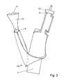
- Fig. 3 about 600 g of hot zeolite granules 11 are filled via the open edge 8 by means of a filling device 12.
- the cooling element 10 is tilted by 180 ° and the filled zeolite granules are joined by means not drawn moldings in the desired geometry.
- a suction adapter 13 which is applied gas-tight at the still open edge 9
- the interior of the cooling element 10 is evacuated to a pressure of less than 2 mbar (absolute). Excess water vapor, air and co-adsorbed gases are sucked out of the zeolite granules via the structural material and further via the mesh lattice strip 3.
- the open edge 9 is sealed by means of externally pressed, hot sealing bars.
- Fig. 4 the cooling element 10 is applied with its evaporator region 16 to the cylindrical part of a bottle 14.
- the cylindrical evaporator region 16 containing the evaporator fleece 5 encloses the cylindrical lower bottle part. It can be stretched by means of (not shown) Velcro straps good thermal conductivity on the bottle wall.
- the area of the cooling element containing the working fluid bag 4 is folded laterally upwards. By pressure on the lying in the working fluid bag 4 opener bag can be perforated.
- the water contained then flows through the channels held open by the mesh grid 3 channels to the structural material.
- the co-funded water in the evaporator fleece 5 is distributed homogeneously.
- the water evaporates and cools over the multi-layer film over a large area of the bottle.
- the effluent water vapor is passed over the total of about 5 cm 2 in cross-section, which spans the structural material to the zeolite 15.
- the zeolite filling heats up to over 80 ° C.
- the sealing layers of the multi-layer polypropylene film can withstand this temperature level. After all, they were subjected to significantly higher loads during charging with hot zeolite.
- thermal decoupling of the hot zeolite region 15 from the cold evaporator region 16 is important.
- the bottle 14 may be slightly tilted backwards.
- the required support is provided by the zeolite region 15, which touches the base with the sealing seam at the filling edge 8.
- the bottle 14 does not have to be removed from the cooling element 10. It can be tilted together with the cooling element 10 advantageously over the filling edge 8 and conveniently pour into glasses available. If the cooling element contains two (or three) working fluid bags, after the zeolite filling has cooled, another working fluid bag can be opened to cool another bottle.
- Fig. 5 shows a horizontal section DD through the evaporator section 16 of Fig. 4 ,
- the multi-layer films 1 and 6 enclose the three-part inner evaporator fleece 5 and two layers of lattice-shaped structural material 2.
- the three-parting of the evaporator fleece 5 formed in addition to the two sealing seams 17 two longitudinal grooves 18.
- the inner multilayer film 6 is contracted and reduced when applying the negative pressure. As a result, wrinkles in the inner multilayer film 6 are minimized. Wrinkles would significantly worsen the thermal contact with the bottle.
- Fig. 6 shows the in Fig. 4 marked longitudinal section EE through the evaporator region 16.
- the multi-layer films 1 and 6 in turn encase the inner evaporator fleece 5 and two layers of structural material 2 and the grid strip 3 and the folded up, bulging working fluid bag 4.
- This contains one in the upper area fixed opener 19, the sharp tips of which can perforate the opposite film of the working fluid bag 4 at external finger pressure.
- the tips are not long enough to hurt through the grid strip and the outer multi-layer film 6.
- Fig. 7 shows the cooling element 10 from the front without a bottle. From this point of view, the capeartige shape of the cooling element 10 is clear. This results forcibly, if the initially flat individual elements Fig. 1 are wound around a cylindrical shape and at the same time the zeolite region 15 is bent backwards.
- the evaporator region 16 can be supplemented by means of adhesive tapes 20 to form an elastic cooling surface for cylindrical containers, while the zeolite region 15 with its lower sealing edge 8 provides a stable support to the rear.
- the working fluid bag 4 is easily accessible for triggering the cooling function.
- Fig. 8 shows a further inventive cooling element 21, the evaporator portion 22 is wound around a standing small beer keg 24 and its zeolite portion 23 projects upwards.
- the evaporator region 22 is tightly bound by means of adhesive strips 25 around the bulbous outer casing of the beer keg 24. His two lower bag corners 26 are sealed at an angle to create space for the bottom tap 27 of beer keg 24.
- the zeolite region 23 of the cooling element 21 is subdivided into four pockets 28, each containing zeolite.
- the arranged in the upper region of the beer keg 24 ventilation opening 29 is easily accessible from above in the ventilation area between the pockets 28. Two working-fluid bags can be recognized by slight bulges 30 at the lower end of the evaporator region 22.
- each working fluid bag contains only a subset of the maximum amount of water adsorbed by the zeolite filling in order to provide enough adsorption capacity for the second cooling process.
- the waste heat from the zeolite area 23 is released to the passing air. Due to the upper positioning, the warm exhaust air can not heat the evaporator section 22.
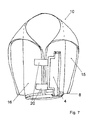
- Fig. 9 shows a horizontal cross section through the zeolite region 23 along the section line FF in Fig. 8 , Inner and outer multilayer films 31, 32 are sealed to span four similarly sized pockets 28 of zeolite filling 33. Along the three sealing seams 34, the four pockets are movable relative to each other. They thus allow the cooling element to conveniently lay around the beer keg and lash down. If, in the extension of the sealing seams 34, the structural material in the evaporator region is also divided, the entire cooling element can also be folded and transported in a space-saving manner before it is applied to the container to be cooled.
- Fig. 10 shows a longitudinal section through the cooling element 21 along the section line GG in Fig. 8 ,
- the multilayer films 31 and 32 envelop the zeolite filling 33 in the upper zeolite region 23 and the structural material 35, the evaporator fleece 36 and the working-agent pouches in the evaporator region 22 37.
- the structural material 35 extends up to the zeolite filling 33 in order to ensure the vapor transport from the evaporator web 36 into the zeolite filling 33.
- the evaporator fleece 36 has two layers in the upper and lower regions in order to ensure optimum connection to a bulbous beer keg.
- the flexibility of the evaporator region 22 according to the invention, in conjunction with the clamping forces of the adhesive tapes, results in an optimal heat-conducting connection to the beer keg.
- FIG. 11 finally shows the individual components of the cooling element 21 prior to assembly.
- a pouch 38 of multilayer films 31, 32 adapted to the dimensions of the beer keg to be cooled has four pockets 28 filled with hot zeolite at the bottom, which are laterally separated from one another via the sealing seams 34.
- the zeolite filling has been uniformly distributed to the four pockets 28 by means of a funnel element 39.
- On the still hot zeolite filling the two-ply structural material 35 is inserted.
- Six, slightly spaced evaporator nonwoven pieces 36 are already attached to the structural material 35, which are each thickened in two layers at the top and bottom.
- the two working fluid pouches 37 are fixed on the side facing away from the evaporator fleece 36.
- the cooling element 21 is evacuated in a vacuum chamber to a final pressure of less than 5 mbar (absolute) and sealed the still open side of the bag.
- the cooling element 21 can now be rotated into any position and deformed according to the invention without the zeolite filling 33 (and the inserted components) leaving its intended position.
Landscapes
- Engineering & Computer Science (AREA)
- Physics & Mathematics (AREA)
- Mechanical Engineering (AREA)
- Thermal Sciences (AREA)
- General Engineering & Computer Science (AREA)
- Chemical & Material Sciences (AREA)
- Combustion & Propulsion (AREA)
- Packages (AREA)
- Sorption Type Refrigeration Machines (AREA)
Applications Claiming Priority (2)
| Application Number | Priority Date | Filing Date | Title |
|---|---|---|---|
| DE200710028559 DE102007028559A1 (de) | 2007-06-19 | 2007-06-19 | Flexible Sorptions-Kühlelemente zum einmaligen Gebrauch |
| DE200710050134 DE102007050134A1 (de) | 2007-06-19 | 2007-10-19 | Flexible Sorptions-Kühlelemente |
Publications (1)
| Publication Number | Publication Date |
|---|---|
| EP2006616A2 true EP2006616A2 (fr) | 2008-12-24 |
Family
ID=39769241
Family Applications (1)
| Application Number | Title | Priority Date | Filing Date |
|---|---|---|---|
| EP08008007A Withdrawn EP2006616A2 (fr) | 2007-06-19 | 2008-04-25 | Eléments de refroidissement de sorption flexibles |
Country Status (4)
| Country | Link |
|---|---|
| US (1) | US20080314070A1 (fr) |
| EP (1) | EP2006616A2 (fr) |
| JP (1) | JP2009002642A (fr) |
| AU (1) | AU2008202263A1 (fr) |
Cited By (2)
| Publication number | Priority date | Publication date | Assignee | Title |
|---|---|---|---|---|
| EP1967799A3 (fr) * | 2007-03-05 | 2011-05-18 | ZEO-TECH Zeolith Technologie GmbH | Elément de refroidissement et de sorption doté d'un organe de réglage et d'une source de chaleur supplémentaire |
| DE102010047371A1 (de) | 2010-10-05 | 2012-04-05 | Zeo-Tech Zeolith-Technologie Gmbh | Sorptions-Kühlelemente |
Families Citing this family (4)
| Publication number | Priority date | Publication date | Assignee | Title |
|---|---|---|---|---|
| EP2453189A1 (fr) | 2010-11-11 | 2012-05-16 | Damm S.a. | Récipient autoréfrigérant |
| US10446357B2 (en) * | 2014-12-02 | 2019-10-15 | Eaton Intelligent Power Limited | Power fuse and fabrication methods with enhanced arc mitigation and thermal management |
| WO2020243637A1 (fr) * | 2019-05-31 | 2020-12-03 | Gobi Technologies Inc. | Système de régulation thermique |
| US20210310711A1 (en) | 2019-05-31 | 2021-10-07 | Gobi Technologies Inc. | Temperature-controlled sorption system |
Citations (5)
| Publication number | Priority date | Publication date | Assignee | Title |
|---|---|---|---|---|
| DE3425419A1 (de) | 1984-07-10 | 1986-01-23 | Fritz Dipl.-Ing. Kaubek | Adiabatische heiz- und kuehlverfahren und tragbare vorrichtungen nach dem adsorptionsprinzip |
| EP0368111A2 (fr) | 1988-11-08 | 1990-05-16 | ZEO-TECH Zeolith Technologie GmbH | Système frigorifique à sorption |
| WO1999037958A1 (fr) | 1998-01-24 | 1999-07-29 | The University Of Nottingham | Dispositif de transfert de chaleur |
| WO2001010738A1 (fr) | 1999-08-04 | 2001-02-15 | Crown Cork & Seal Technologies Corporation | Canette a refroidissement integre |
| US6474100B1 (en) | 2001-04-25 | 2002-11-05 | Thermal Products Development Inc. | Evacuated sorbent assembly and cooling device |
Family Cites Families (24)
| Publication number | Priority date | Publication date | Assignee | Title |
|---|---|---|---|---|
| DE3207656A1 (de) * | 1982-02-15 | 1983-08-25 | Hieronimi, Ulrich, 8000 München | Sorptionsapparate und verfahren fuer ihren betrieb |
| DE3342985A1 (de) * | 1983-11-28 | 1985-06-13 | Fritz Dipl.-Ing. Kaubek | Kontinuierlichwirkende sorptionsapparate und verfahren zu deren betrieb |
| DE3347700C2 (de) * | 1983-12-31 | 1994-07-07 | Zeolith Tech | Zeolithformling mit hoher Wärmeleitung und Verfahren zur Herstellung |
| DE3413349C2 (de) * | 1984-04-09 | 1986-09-25 | Fritz Dipl.-Ing. Kaubek | Verfahren und Vorrichtung zum Heizen mit einer periodischen Adsorptionsspeicher-Wärmepumpe |
| DE3521484A1 (de) * | 1985-06-14 | 1986-12-18 | Fritz Dipl.-Ing. Kaubek | Adsorptionskuehler |
| DE3837880A1 (de) * | 1988-11-08 | 1990-05-10 | Zeolith Tech | Kuehlbehaelter fuer einen sorptionsapparat |
| DE3901558A1 (de) * | 1989-01-20 | 1990-07-26 | Zeolith Tech | Sorptionsbehaelter fuer feste sorptionsmittel |
| DE4003107A1 (de) * | 1990-02-02 | 1991-08-08 | Zeolith Tech | Eiserzeuger nach dem sorptionsprinzip |
| US5113666A (en) * | 1990-10-05 | 1992-05-19 | Mainstream Engineering Corp. | Cooling device for hazardous materials suits |
| DE4121131A1 (de) * | 1991-06-26 | 1993-01-07 | Zeolith Tech | Sorptionsmittelbehaelter-anordnung und sorptionsverfahren mit regenerativem waermetausch |
| DE4126960A1 (de) * | 1991-08-14 | 1993-02-18 | Zeolith Tech | Sorptionsapparat zum kuehlen und/oder heizen |
| DE4138114A1 (de) * | 1991-11-19 | 1993-05-27 | Zeolith Tech | Kuehlvorrichtung und kuehlverfahren zur kuehlung eines mediums innerhalb eines gefaesses |
| EP0577869B1 (fr) * | 1992-07-06 | 1997-01-08 | ZEO-TECH Zeolith Technologie GmbH | Système frigorifique avec un conduit collecteur étanche travaillant sous vide pour la vapeur du fluide de travail |
| DE4243817A1 (de) * | 1992-12-23 | 1994-06-30 | Zeolith Tech | Adapter für ein Sorptionssystem und Verfahren zur Verwendung dieses Adapters |
| DE4243816A1 (de) * | 1992-12-23 | 1994-06-30 | Zeolith Tech | Sorptionsmittel-Patrone |
| EP0781393B1 (fr) * | 1994-09-12 | 1999-12-15 | Electrolux Leisure Appliances Ag | Unite de refrigeration par sorption |
| US6359560B1 (en) * | 1998-11-12 | 2002-03-19 | Smith Micro Software | Computer system with motion-triggered alarm procedure |
| US6341491B1 (en) * | 1999-01-25 | 2002-01-29 | Bass Public Limited Company | Heat transfer device |
| DE10016352A1 (de) * | 2000-04-03 | 2001-10-04 | Zeolith Tech | Sorptionskühler |
| DE10028030A1 (de) * | 2000-06-09 | 2001-12-13 | Zeolith Tech | Sorptionsvorrichtung zum Heizen und Kühlen von Gasströmen |
| US6688132B2 (en) * | 2001-06-06 | 2004-02-10 | Nanopore, Inc. | Cooling device and temperature-controlled shipping container using same |
| DE10250510A1 (de) * | 2002-10-29 | 2004-05-19 | Zeo-Tech Zeolith-Technologie Gmbh | Adsorptions-Kühlapparat mit Pufferspeicher |
| DE102005034297A1 (de) * | 2005-02-25 | 2006-08-31 | Zeo-Tech Zeolith-Technologie Gmbh | Sorptions-Kühlelement mit gasdichter Folie |
| EP1967799B1 (fr) * | 2007-03-05 | 2012-11-21 | ZEO-TECH Zeolith Technologie GmbH | Elément de refroidissement et de sorption doté d'un organe de réglage et d'une source de chaleur supplémentaire |
-
2008
- 2008-04-25 EP EP08008007A patent/EP2006616A2/fr not_active Withdrawn
- 2008-05-22 AU AU2008202263A patent/AU2008202263A1/en not_active Abandoned
- 2008-06-05 US US12/157,002 patent/US20080314070A1/en not_active Abandoned
- 2008-06-16 JP JP2008156415A patent/JP2009002642A/ja active Pending
Patent Citations (5)
| Publication number | Priority date | Publication date | Assignee | Title |
|---|---|---|---|---|
| DE3425419A1 (de) | 1984-07-10 | 1986-01-23 | Fritz Dipl.-Ing. Kaubek | Adiabatische heiz- und kuehlverfahren und tragbare vorrichtungen nach dem adsorptionsprinzip |
| EP0368111A2 (fr) | 1988-11-08 | 1990-05-16 | ZEO-TECH Zeolith Technologie GmbH | Système frigorifique à sorption |
| WO1999037958A1 (fr) | 1998-01-24 | 1999-07-29 | The University Of Nottingham | Dispositif de transfert de chaleur |
| WO2001010738A1 (fr) | 1999-08-04 | 2001-02-15 | Crown Cork & Seal Technologies Corporation | Canette a refroidissement integre |
| US6474100B1 (en) | 2001-04-25 | 2002-11-05 | Thermal Products Development Inc. | Evacuated sorbent assembly and cooling device |
Cited By (3)
| Publication number | Priority date | Publication date | Assignee | Title |
|---|---|---|---|---|
| EP1967799A3 (fr) * | 2007-03-05 | 2011-05-18 | ZEO-TECH Zeolith Technologie GmbH | Elément de refroidissement et de sorption doté d'un organe de réglage et d'une source de chaleur supplémentaire |
| DE102010047371A1 (de) | 2010-10-05 | 2012-04-05 | Zeo-Tech Zeolith-Technologie Gmbh | Sorptions-Kühlelemente |
| EP2439467A3 (fr) * | 2010-10-05 | 2013-11-13 | ZEO-TECH Zeolith Technologie GmbH | Elément de refroidissement par sorption |
Also Published As
| Publication number | Publication date |
|---|---|
| US20080314070A1 (en) | 2008-12-25 |
| JP2009002642A (ja) | 2009-01-08 |
| AU2008202263A1 (en) | 2009-01-22 |
Similar Documents
| Publication | Publication Date | Title |
|---|---|---|
| DE102005034297A1 (de) | Sorptions-Kühlelement mit gasdichter Folie | |
| EP2006616A2 (fr) | Eléments de refroidissement de sorption flexibles | |
| EP1967799B1 (fr) | Elément de refroidissement et de sorption doté d'un organe de réglage et d'une source de chaleur supplémentaire | |
| DE102007010981A1 (de) | Sorptions-Kühlelement mit Regelorgan | |
| DE3425419C2 (de) | Adiabatische Heiz- und Kühlvorrichtungen nach dem Adsorptionsprinzip | |
| EP1926931B1 (fr) | Procede pour fabriquer un element d'isolation par le vide, enveloppe d'une pellicule et rempli de poudre | |
| DE60113241T2 (de) | Hilfe beim vakuumverpacken | |
| DE102006008786B4 (de) | Adsorptions-Wärmepumpe, Adsorptions-Kältemaschine und darin enthaltene Adsorberelemente auf Basis eines offenporigen wärmeleitenden Festkörpers | |
| DE4138114A1 (de) | Kuehlvorrichtung und kuehlverfahren zur kuehlung eines mediums innerhalb eines gefaesses | |
| EP2643645B1 (fr) | Machine frigorifique à adsorption avec une cuve à vide permettant d'éliminer les gaz étrangers | |
| DE69411377T2 (de) | Chemischer reaktor, kältemaschine und behälter ausgestattet mit diesem reaktor und reagenzpatrone dafür | |
| EP1519125A2 (fr) | Procédé et appareil pour une solidification rapide de matières contenant de l'eau | |
| EP1746365A2 (fr) | Elément de refroidissement à sorption avec une feuille étanche aux gaz | |
| DE60210496T2 (de) | Wärmeaustauscher | |
| DE102008015677A1 (de) | Selbsterwärmendes Heizelement mit Sorptionsmittel | |
| DE102007050134A1 (de) | Flexible Sorptions-Kühlelemente | |
| EP2439467A2 (fr) | Elément de refroidissement par sorption | |
| DE2622699B2 (en) | Absorption heat accumulator element - has absorbent and collector in common tubular gastight vessel with space between | |
| DE2939904A1 (de) | Kuehlschrank | |
| EP1902261A1 (fr) | Echangeur thermique et contenant de temperation comportant un echangeur thermique | |
| DE60038729T2 (de) | Aufbereitung von materialien zur kälteerzeugung | |
| EP2895804B1 (fr) | Récipient de collecte et procédé de récupération de fluide de travail dans des dispositifs de sorption | |
| DE69729274T2 (de) | Kühlgerät für ein Fluidum | |
| DE19728116C2 (de) | Wärmeübertrager zur Übertragung von Wärme zwischen einem Adsorbens und einem Wärmetransportmedium und Verfahren zur Herstellung eines solchen Wärmeübertragers | |
| EP1150077A1 (fr) | Conteneur à sorption avec une enveloppe flexible |
Legal Events
| Date | Code | Title | Description |
|---|---|---|---|
| PUAI | Public reference made under article 153(3) epc to a published international application that has entered the european phase |
Free format text: ORIGINAL CODE: 0009012 |
|
| AK | Designated contracting states |
Kind code of ref document: A2 Designated state(s): AT BE BG CH CY CZ DE DK EE ES FI FR GB GR HR HU IE IS IT LI LT LU LV MC MT NL NO PL PT RO SE SI SK TR |
|
| AX | Request for extension of the european patent |
Extension state: AL BA MK RS |
|
| STAA | Information on the status of an ep patent application or granted ep patent |
Free format text: STATUS: THE APPLICATION IS DEEMED TO BE WITHDRAWN |
|
| 18D | Application deemed to be withdrawn |
Effective date: 20131101 |