EP0368111A2 - Système frigorifique à sorption - Google Patents
Système frigorifique à sorption Download PDFInfo
- Publication number
- EP0368111A2 EP0368111A2 EP19890120078 EP89120078A EP0368111A2 EP 0368111 A2 EP0368111 A2 EP 0368111A2 EP 19890120078 EP19890120078 EP 19890120078 EP 89120078 A EP89120078 A EP 89120078A EP 0368111 A2 EP0368111 A2 EP 0368111A2
- Authority
- EP
- European Patent Office
- Prior art keywords
- container
- cooling
- sorption
- cooling system
- working fluid
- Prior art date
- Legal status (The legal status is an assumption and is not a legal conclusion. Google has not performed a legal analysis and makes no representation as to the accuracy of the status listed.)
- Granted
Links
Images

Classifications
-
- F—MECHANICAL ENGINEERING; LIGHTING; HEATING; WEAPONS; BLASTING
- F25—REFRIGERATION OR COOLING; COMBINED HEATING AND REFRIGERATION SYSTEMS; HEAT PUMP SYSTEMS; MANUFACTURE OR STORAGE OF ICE; LIQUEFACTION SOLIDIFICATION OF GASES
- F25B—REFRIGERATION MACHINES, PLANTS OR SYSTEMS; COMBINED HEATING AND REFRIGERATION SYSTEMS; HEAT PUMP SYSTEMS
- F25B17/00—Sorption machines, plants or systems, operating intermittently, e.g. absorption or adsorption type
- F25B17/08—Sorption machines, plants or systems, operating intermittently, e.g. absorption or adsorption type the absorbent or adsorbent being a solid, e.g. salt
-
- F—MECHANICAL ENGINEERING; LIGHTING; HEATING; WEAPONS; BLASTING
- F25—REFRIGERATION OR COOLING; COMBINED HEATING AND REFRIGERATION SYSTEMS; HEAT PUMP SYSTEMS; MANUFACTURE OR STORAGE OF ICE; LIQUEFACTION SOLIDIFICATION OF GASES
- F25D—REFRIGERATORS; COLD ROOMS; ICE-BOXES; COOLING OR FREEZING APPARATUS NOT OTHERWISE PROVIDED FOR
- F25D11/00—Self-contained movable devices, e.g. domestic refrigerators
Definitions
- the invention relates to a sorption cooling system comprising a cooling container and an adsorption container.
- compressor cooling units essentially consist of a, mostly hermetically sealed, compressor, a forced-cooled condenser, a collecting container for the liquid refrigerant, a temperature-controlled expansion valve and an evaporator.
- the cold generated in the evaporator must be temporarily stored in a cold buffer, since the evaporator capacity is significantly lower than the cooling capacity required during a dispensing process.
- the compression device has a longer running time than the sum of the individual tapping operations.
- Today's cold buffers either have a water tank with a capacity of up to 20 l or a large aluminum block.
- the biggest disadvantage of the aluminum block is that the storage capacity is relatively small, so that when more than 0.5 l of liquid are drawn, the cooling effect is already exhausted.
- the water storage device has the disadvantage that after filling the water, the device must be in operation for a long time in order to cool the water filling itself.
- the water tank must be provided with an additional agitator, which the water around the evaporator and cooling coils for better heat exchange pumped around. This mechanical agitator is extremely susceptible to failure and therefore often leads to the failure of the entire cooling device.
- Such compression refrigerators are used to cool beverages, e.g. B. beer, lemonades etc. used in marquees or at parties. Your use in the private individual z. B. for cooling a borrowed beer barrel is only possible to a limited extent, since the high complexity of the device requires a lot of technical expertise from the user and the refrigerator cannot be used profitably for the beverage publisher due to the high acquisition or maintenance costs.
- Sorption apparatus is understood to mean devices in which a liquid or solid sorbent sorbs a second, higher-boiling agent, the working fluid sorbs with heat release. Before the working medium is sorbed by sorbent, it evaporates in a cooling container while absorbing heat. The evaporation temperatures range from -40 ° to + 40 ° C, depending on the type of working fluid or the area in which the sorbent is used. Sorption devices with solid adsorbents, so-called adsorption devices work periodically, i. H. A sorption phase is always followed by a desorption phase in which the working fluid is separated from the adsorbent. The working medium cannot be sorbed during the desorption phase and therefore cannot evaporate. There is therefore no cold in the cooling container.
- a periodically operating adsorption cooling apparatus in which an ice bank is built up during the adsorption phase by partial evaporation of the working medium water.
- the apparatus exists thereby from an adsorption container which is filled with the sorbent zeolite, a cooling container which contains the working medium water and from which a vapor channel between the adsorption container and the cooling container can be shut off by means of a shut-off device.
- Cold for example for cooling a cooling bag, can be dissipated via the container surfaces of the cooling container, while heat can be called up via the container walls of the adsorption container.
- the working medium is desorbed from the sorbent by supplying desorption heat to the adsorption container and reliquefied in the cooling container with heat being released.
- the shut-off device is closed and the adsorption container is cooled. In this state, the adsorption apparatus can be stored for any length of time.
- the object of the present invention is to show a sorption cooling system which is characterized by a simple and inexpensive design and with the aid of which larger amounts of liquid can be cooled to temperatures between + 4 ° and + 10 ° C from any initial temperature with little control effort.
- the sorption cooling system consists of a transportable cooling unit and a stationary charging station that can be separated therefrom. With a single charging station, a multitude is more portable Cooling units can be regenerated. In order to keep the cooling units easily transportable, they only consist of the technically absolutely necessary parts, namely an adsorption container filled with an adsorbent, a cooling container that contains the liquid working fluid and a heat exchanger embedded therein, a working fluid vapor channel that connects the adsorption container with the cooling container connects and a shut-off device that makes the steam channel shut off.
- the working fluid When loaded, the working fluid is separated from the adsorbent as a liquid in the cooling container.
- the shut-off device is closed, adsorption and working media are at ambient temperature.
- the cooling unit can be delivered to the customer, e.g. B. can be borrowed together with a beer keg.
- the customer connects the beverage lines to the heat exchanger and opens the shut-off device.
- the working fluid can now evaporate in the cooling container, flow via the working fluid vapor channel to the adsorbent and can be adsorbed by the latter with the release of heat.
- the heat of adsorption is dissipated via the walls of the adsorption container, for example to the ambient air.
- the adsorption container can also advantageously be coupled to a water container, the water content of which can absorb the heat of adsorption.
- the evaporation of the working fluid creates cold in the cooling container, which cools the medium flowing through the heat exchanger, for example a beverage.
- the outlet temperature of the beverage can be regulated by temperature-controlled opening and closing of the shut-off device.
- Zeolite is a crystalline mineral that consists of a regular framework structure made of silicon and aluminum oxides. This scaffold structure contains small cavities in which water molecules can be adsorbed with the release of heat. Within the framework structure, the water molecules are exposed to strong field forces, which liquefy the molecules in the lattice and bind them in a liquid-like phase. The strength of the binding forces acting on the water molecules depends on the amount of water already contained in the structure and the temperature of the zeolite. For practical use, up to 25 grams of water can be adsorbed per 100 grams of zeolite. Zeolites are solid substances without annoying thermal expansion during the adsorption or desorption reaction. The framework structure is freely accessible from all sides for the water vapor molecules. The cooling unit can therefore be used in any position.
- the cooling capacity of the cooling unit is determined by the amount of zeolite filled in and the adsorbent temperature reached at the end of the tap time. This amount can therefore be designed so that one cooling unit is sufficient to cool a complete beverage container (beer keg, lemonade container, etc.).
- the adsorption container After returning the discharged cooling unit, it is placed with the adsorption container in an opening in the heating cabinet of the charging station and desorbed. During this charging process, the adsorbent is heated and the working fluid is evaporated. The vaporous working fluid is re-liquefied in a suitable heat exchanger and returned to the cooling tank. The temperature of the heating cabinet is between 250 ° and 350 ° C at the end of the charging phase. As soon as the adsorbent is heated up and the working fluid is desorbed, the shut-off device is closed and the entire cooling unit is separated from the charging station. The adsorption container can now cool down but cannot draw off any water vapor from the cooling container. The cooling unit can be stored at room temperature until the next use.
- the charging station Since the charging station remains with the respective rental company, it represents only a one-time purchase. All expensive and heavy components, such as electrical heating, temperature control, insulation of the heating cabinet and additional components such as evacuation unit, cooling fan, etc. can be mounted on the charging station.
- the portable cooling unit is therefore light and inexpensive. It therefore does not need its own energy connection for the customer.
- the cooling capacity is immediately available. In addition, it is characterized by a high cooling reserve, so that longer tap operation is possible. After removing the cooling capacity, the cooling unit is worthless to the customer without a separate charging station. He therefore willingly returns them to the lender against reimbursement of his pledge.
- the further heat exchanger of the cooling unit via which the heat of condensation of the working fluid vapor is removed during charging in the charging station, can advantageously be a container wall of the cooling container.
- the charging station can advantageously be equipped with a cooling fan that blows ambient air onto the container wall of the cooling container intended for condensation.
- this heat exchanger is surrounded by the liquid working fluid according to the invention, it must protrude from the liquid working fluid for this purpose. This is achieved, for example, by rotating the cooling container when it is introduced into the heating cabinet to such an extent that the heat exchanger at least partially protrudes from the amount of liquid working fluid. Tap water can flow through the heat exchanger for cooling.
- the shut-off device is required to have a high level of vacuum tightness, particularly when using the pair of zeolite / water substances. Furthermore, the shut-off device be designed so that it opens automatically and allows the working fluid vapor to flow into the cooling container as soon as the vapor pressure in the adsorption container is higher than the vapor pressure in the cooling container. In this way it is ensured that during the desorption phase, if the shut-off device is accidentally closed, no excess pressure can arise in the adsorption container.
- the cooling unit can be equipped with an overpressure safety device.
- a droplet separator can be arranged in the cooling container, which retains droplets of working fluid that arise during the evaporation process.
- the adsorption container is advantageously designed so that desorption heat can be supplied via its container walls in the heating cabinet or the adsorption heat can be removed during the adsorption phase.
- Flat containers which are connected to one another via the working medium steam duct, are particularly suitable for this purpose.
- the amount of adsorbent expediently contains steam channels through which the inflowing working medium is evenly distributed.
- the transportable cooling unit shown in perspective in FIG. 1 consists of six flat adsorption containers 1, which are connected to one another and to the cooling container 3 via a working medium steam channel 2.
- the working medium steam channel 2 can be shut off via a shut-off device 4.
- In the lower part of the cooling container 3 is the inlet and outlet 5.6 to the heat exchanger, not shown.
- Cooling fins 7 are arranged on the outer wall of the cooling container 3 and increase the surface area in order to improve the dissipation of the heat of condensation into the ambient air.
- the stationary charging station is also shown in a perspective view.
- a heating cabinet 8 is provided with an opening 9 in which the adsorption containers 1 of the cooling unit can be accommodated.
- a recess 10 is provided at a corresponding point in the heating cabinet, which allows the lid 11 of the heating cabinet to be closed after the adsorption container 1 has been inserted.
- the cooling container 3 is located via two cooling fans 12, 13, which press ambient air onto the cooling fins 7 of the cooling container.
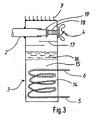
- the cooling container 3 is shown in section.
- a heat exchanger 14 with inlet or outlet 5, 6, embedded in a quantity of water 15.
- a droplet separator 17 is arranged above the ice layer 16.
- a broiled opens into the upper part of the cooling container Chen illustrated working medium steam channel 2.
- the shut-off device 4 consists of a metallic bellows 18 and a flat seal 19 which rests on the mouth of the working medium steam channel 2 in the closed state.
- cooling fins 7 are attached to enlarge the surface.
Landscapes
- Engineering & Computer Science (AREA)
- Physics & Mathematics (AREA)
- Mechanical Engineering (AREA)
- Thermal Sciences (AREA)
- General Engineering & Computer Science (AREA)
- Chemical & Material Sciences (AREA)
- Combustion & Propulsion (AREA)
- Sorption Type Refrigeration Machines (AREA)
- Devices That Are Associated With Refrigeration Equipment (AREA)
- Sampling And Sample Adjustment (AREA)
Priority Applications (1)
| Application Number | Priority Date | Filing Date | Title |
|---|---|---|---|
| AT89120078T ATE102334T1 (de) | 1988-11-08 | 1989-10-30 | Sorptionskuehlsystem. |
Applications Claiming Priority (2)
| Application Number | Priority Date | Filing Date | Title |
|---|---|---|---|
| DE3837872 | 1988-11-08 | ||
| DE3837872A DE3837872A1 (de) | 1988-11-08 | 1988-11-08 | Sorptionskuehlsystem |
Publications (3)
| Publication Number | Publication Date |
|---|---|
| EP0368111A2 true EP0368111A2 (fr) | 1990-05-16 |
| EP0368111A3 EP0368111A3 (fr) | 1991-11-27 |
| EP0368111B1 EP0368111B1 (fr) | 1994-03-02 |
Family
ID=6366729
Family Applications (1)
| Application Number | Title | Priority Date | Filing Date |
|---|---|---|---|
| EP89120078A Expired - Lifetime EP0368111B1 (fr) | 1988-11-08 | 1989-10-30 | Système frigorifique à sorption |
Country Status (4)
| Country | Link |
|---|---|
| US (1) | US5038581A (fr) |
| EP (1) | EP0368111B1 (fr) |
| AT (1) | ATE102334T1 (fr) |
| DE (2) | DE3837872A1 (fr) |
Cited By (16)
| Publication number | Priority date | Publication date | Assignee | Title |
|---|---|---|---|---|
| EP0368111A3 (fr) * | 1988-11-08 | 1991-11-27 | ZEO-TECH Zeolith Technologie GmbH | Système frigorifique à sorption |
| EP0527466A1 (fr) * | 1991-08-14 | 1993-02-17 | ZEO-TECH Zeolith Technologie GmbH | Procédé de sorption pour refroidir et/ou chauffer |
| EP1054222A2 (fr) | 1999-05-19 | 2000-11-22 | ZEO-TECH Zeolith Technologie GmbH | Dispositif et procédé pour refroidir un liquide dans un récipient |
| EP1143210A1 (fr) | 2000-04-03 | 2001-10-10 | ZEO-TECH Zeolith Technologie GmbH | Refroidisseur à sorption |
| EP1162415A1 (fr) | 2000-06-09 | 2001-12-12 | ZEO-TECH Zeo-Tech GmbH | Dispositif à sorption pour le rechauffement ou le refroidissement des écoulements de gaz |
| EP1443288A2 (fr) | 2003-01-28 | 2004-08-04 | ZEO-TECH Zeolith Technologie GmbH | Conteneur réfrigéré avec une machine frigorifique à absorption |
| EP1519125A2 (fr) | 2003-09-25 | 2005-03-30 | ZEO-TECH Zeolith Technologie GmbH | Procédé et appareil pour une solidification rapide de matières contenant de l'eau |
| EP1746365A2 (fr) | 2005-07-22 | 2007-01-24 | ZEO-TECH Zeolith Technologie GmbH | Elément de refroidissement à sorption avec une feuille étanche aux gaz |
| EP1967799A2 (fr) | 2007-03-05 | 2008-09-10 | ZEO-TECH Zeolith Technologie GmbH | Elément de refroidissement et de sorption doté d'un organe de réglage et d'une source de chaleur supplémentaire |
| DE102007010981A1 (de) | 2007-03-05 | 2008-09-11 | Zeo-Tech Zeolith-Technologie Gmbh | Sorptions-Kühlelement mit Regelorgan |
| EP2006616A2 (fr) | 2007-06-19 | 2008-12-24 | ZEO-TECH Zeolith Technologie GmbH | Eléments de refroidissement de sorption flexibles |
| DE102007028559A1 (de) | 2007-06-19 | 2008-12-24 | Zeo-Tech Zeolith-Technologie Gmbh | Flexible Sorptions-Kühlelemente zum einmaligen Gebrauch |
| DE102008020605A1 (de) | 2008-04-24 | 2009-10-29 | Schwörer Haus KG | Heiz- und Kühlanordnung |
| DE102010047371A1 (de) | 2010-10-05 | 2012-04-05 | Zeo-Tech Zeolith-Technologie Gmbh | Sorptions-Kühlelemente |
| DE102015002421A1 (de) | 2015-02-26 | 2016-09-01 | Zeo-Tech Zeolith-Technologie Gmbh | Vakuum-Gerät mit Sorptionsmittel-Patrone |
| DE10238510B4 (de) * | 2001-08-22 | 2019-12-05 | Vaillant Gmbh | Wärmepumpen-Modul für eine Adsorptionswärmepumpe |
Families Citing this family (24)
| Publication number | Priority date | Publication date | Assignee | Title |
|---|---|---|---|---|
| US5664427A (en) * | 1989-03-08 | 1997-09-09 | Rocky Research | Rapid sorption cooling or freezing appliance |
| US5598721A (en) * | 1989-03-08 | 1997-02-04 | Rocky Research | Heating and air conditioning systems incorporating solid-vapor sorption reactors capable of high reaction rates |
| US5186020A (en) * | 1991-01-23 | 1993-02-16 | Rocky Research | Portable cooler |
| US5628205A (en) * | 1989-03-08 | 1997-05-13 | Rocky Research | Refrigerators/freezers incorporating solid-vapor sorption reactors capable of high reaction rates |
| DE4029084A1 (de) * | 1990-09-13 | 1992-03-19 | Draegerwerk Ag | Kuehlvorrichtung zur atemgaskuehlung in einem atemschutzgeraet |
| MX9701840A (es) * | 1994-09-12 | 1997-06-28 | Electrolux Leisure Appliances | Unidad de refrigeracion de absorcion. |
| GB9513606D0 (en) * | 1995-07-04 | 1995-09-06 | Boc Group Plc | Apparatus for chilling fluids |
| JPH11514733A (ja) * | 1995-11-01 | 1999-12-14 | ジェイ.,ジュニア バウアー,ジョン | バランス吸着式冷蔵装置 |
| BR9808742A (pt) * | 1997-05-08 | 2001-10-02 | David A Zornes | Refrigerador adsorvente com separador |
| US6102107A (en) * | 1998-12-11 | 2000-08-15 | Uop Llc | Apparatus for use in sorption cooling processes |
| US6688132B2 (en) | 2001-06-06 | 2004-02-10 | Nanopore, Inc. | Cooling device and temperature-controlled shipping container using same |
| US6584797B1 (en) | 2001-06-06 | 2003-07-01 | Nanopore, Inc. | Temperature-controlled shipping container and method for using same |
| US6601404B1 (en) | 2001-08-17 | 2003-08-05 | Nanopore, Inc. | Cooling device |
| US6591630B2 (en) | 2001-08-17 | 2003-07-15 | Nanopore, Inc. | Cooling device |
| DE10250510A1 (de) * | 2002-10-29 | 2004-05-19 | Zeo-Tech Zeolith-Technologie Gmbh | Adsorptions-Kühlapparat mit Pufferspeicher |
| FR2851329B1 (fr) * | 2003-02-17 | 2006-02-03 | Airbus | Procede de maintien au froid d'aliments a bord d'aeronefs et moyen de mise en oeuvre |
| KR20070051835A (ko) * | 2004-06-08 | 2007-05-18 | 나노포어 인코포레이티드 | 차량 냉각 장치에 이용되는 수착 냉각 시스템 및 이에 관한방법 |
| DE102005034297A1 (de) * | 2005-02-25 | 2006-08-31 | Zeo-Tech Zeolith-Technologie Gmbh | Sorptions-Kühlelement mit gasdichter Folie |
| GB2449522A (en) * | 2007-05-22 | 2008-11-26 | 4Energy Ltd | Temperature controlled equipment cabinet comprising an absorption refrigerator system with an evaporator pipe located within a fluid containing enclosure |
| DE102011081052B4 (de) | 2011-08-16 | 2017-07-27 | BSH Hausgeräte GmbH | Kühleinrichtung und Getränkespender |
| USD840446S1 (en) * | 2016-08-04 | 2019-02-12 | Viking Cold Solutions, Inc. | Material holding bottle |
| JP7360402B2 (ja) | 2018-03-02 | 2023-10-12 | インキャン ユーエスエー エルエルシー. | 自己冷却装置及び方法 |
| KR102848671B1 (ko) | 2019-05-31 | 2025-08-22 | 고비 테크놀로지스 인크. | 열 조절 시스템 |
| US20210310711A1 (en) | 2019-05-31 | 2021-10-07 | Gobi Technologies Inc. | Temperature-controlled sorption system |
Family Cites Families (28)
| Publication number | Priority date | Publication date | Assignee | Title |
|---|---|---|---|---|
| US992560A (en) * | 1910-01-22 | 1911-05-16 | Ralph V Heuser | Refrigerating device. |
| US1512623A (en) * | 1921-09-17 | 1924-10-21 | Charles E Maxwell | Refrigerating apparatus |
| DE410423C (de) * | 1923-09-19 | 1925-02-26 | Escher Wyss Maschf Ag | Verdampfer bei Absorptionsmaschinen fuer Kleinkaeltebedarf |
| GB228136A (en) * | 1924-01-23 | 1926-04-06 | Silica Gel Corp | An improved method of and apparatus for refrigeration |
| GB312422A (en) * | 1928-12-12 | 1929-05-30 | Naamlooze Vennootschap The Kod | Improvements in absorption refrigerating apparatus |
| US1808056A (en) * | 1929-05-09 | 1931-06-02 | Robert J Mitchell | Refrigerating system |
| US2027571A (en) * | 1931-10-20 | 1936-01-14 | Siemens Ag | Method for the transformation of heat |
| US2053683A (en) * | 1931-10-31 | 1936-09-08 | Schlumbohm Peter | Cooling system |
| DE636013C (de) * | 1935-04-07 | 1936-09-29 | Eberhard Sprenger Dipl Ing | Trockene periodische Absorptionskaeltemaschine |
| US2323902A (en) * | 1937-07-16 | 1943-07-13 | Kleen Nils Erland Af | Absorption or adsorption refrigerating apparatus |
| US2990693A (en) * | 1957-09-04 | 1961-07-04 | Cie Ind Des Procedes Raoul Pic | Refrigerator system |
| US3018638A (en) * | 1959-11-13 | 1962-01-30 | Eric H Winkler | Portable refrigeration apparatus |
| US3257817A (en) * | 1964-07-28 | 1966-06-28 | Carrier Corp | Refrigeration apparatus and method |
| DE2715075A1 (de) * | 1977-04-04 | 1978-10-12 | Helfried Crede | Verfahren und vorrichtung zur energiegewinnung aus umgebenden waermequellen |
| DE2720561A1 (de) * | 1977-05-07 | 1978-11-09 | Tchernev Dimiter I | Sorptionssystem fuer die nutzbarmachung schwacher (solarer) waermequellen |
| SE7706357L (sv) * | 1977-05-31 | 1978-12-01 | Brunberg Ernst Ake | Sett vid kylning av ett utrymme samt anordning for genomforande av settet |
| US4250720A (en) * | 1979-03-12 | 1981-02-17 | Israel Siegel | Disposable non-cyclic sorption temperature-changers |
| DE3207656A1 (de) * | 1982-02-15 | 1983-08-25 | Hieronimi, Ulrich, 8000 München | Sorptionsapparate und verfahren fuer ihren betrieb |
| FR2530791A1 (fr) * | 1982-07-22 | 1984-01-27 | Jeumont Schneider | Dispositif refrigerateur a energie solaire |
| DE3342985A1 (de) * | 1983-11-28 | 1985-06-13 | Fritz Dipl.-Ing. Kaubek | Kontinuierlichwirkende sorptionsapparate und verfahren zu deren betrieb |
| DE3347700C2 (de) * | 1983-12-31 | 1994-07-07 | Zeolith Tech | Zeolithformling mit hoher Wärmeleitung und Verfahren zur Herstellung |
| DE3413349C2 (de) * | 1984-04-09 | 1986-09-25 | Fritz Dipl.-Ing. Kaubek | Verfahren und Vorrichtung zum Heizen mit einer periodischen Adsorptionsspeicher-Wärmepumpe |
| DE3425419C2 (de) * | 1984-07-10 | 1993-12-09 | Zeolith Tech | Adiabatische Heiz- und Kühlvorrichtungen nach dem Adsorptionsprinzip |
| ATE68257T1 (de) * | 1985-05-28 | 1991-10-15 | Zeolith Tech | Vorrichtung und verfahren zur erwaermung von wasser durch einen periodischen adsorptionsprozess. |
| DE3521484A1 (de) * | 1985-06-14 | 1986-12-18 | Fritz Dipl.-Ing. Kaubek | Adsorptionskuehler |
| FR2585812B1 (fr) * | 1985-07-30 | 1987-10-23 | Jeumont Schneider | Machine thermique a adsorption-desorption |
| US4759191A (en) * | 1987-07-07 | 1988-07-26 | Liquid Co2 Engineering, Inc. | Miniaturized cooling device and method of use |
| DE3837872A1 (de) * | 1988-11-08 | 1990-05-10 | Zeolith Tech | Sorptionskuehlsystem |
-
1988
- 1988-11-08 DE DE3837872A patent/DE3837872A1/de not_active Withdrawn
-
1989
- 1989-10-30 AT AT89120078T patent/ATE102334T1/de not_active IP Right Cessation
- 1989-10-30 EP EP89120078A patent/EP0368111B1/fr not_active Expired - Lifetime
- 1989-10-30 DE DE89120078T patent/DE58907091D1/de not_active Expired - Lifetime
- 1989-11-07 US US07/432,489 patent/US5038581A/en not_active Expired - Lifetime
Cited By (20)
| Publication number | Priority date | Publication date | Assignee | Title |
|---|---|---|---|---|
| EP0368111A3 (fr) * | 1988-11-08 | 1991-11-27 | ZEO-TECH Zeolith Technologie GmbH | Système frigorifique à sorption |
| EP0527466A1 (fr) * | 1991-08-14 | 1993-02-17 | ZEO-TECH Zeolith Technologie GmbH | Procédé de sorption pour refroidir et/ou chauffer |
| EP1054222A2 (fr) | 1999-05-19 | 2000-11-22 | ZEO-TECH Zeolith Technologie GmbH | Dispositif et procédé pour refroidir un liquide dans un récipient |
| EP1143210A1 (fr) | 2000-04-03 | 2001-10-10 | ZEO-TECH Zeolith Technologie GmbH | Refroidisseur à sorption |
| EP1162415A1 (fr) | 2000-06-09 | 2001-12-12 | ZEO-TECH Zeo-Tech GmbH | Dispositif à sorption pour le rechauffement ou le refroidissement des écoulements de gaz |
| DE10238510B4 (de) * | 2001-08-22 | 2019-12-05 | Vaillant Gmbh | Wärmepumpen-Modul für eine Adsorptionswärmepumpe |
| EP1443288A2 (fr) | 2003-01-28 | 2004-08-04 | ZEO-TECH Zeolith Technologie GmbH | Conteneur réfrigéré avec une machine frigorifique à absorption |
| EP1519125A2 (fr) | 2003-09-25 | 2005-03-30 | ZEO-TECH Zeolith Technologie GmbH | Procédé et appareil pour une solidification rapide de matières contenant de l'eau |
| EP1746365A2 (fr) | 2005-07-22 | 2007-01-24 | ZEO-TECH Zeolith Technologie GmbH | Elément de refroidissement à sorption avec une feuille étanche aux gaz |
| DE102007057748A1 (de) | 2007-03-05 | 2009-06-10 | Zeo-Tech Zeolith-Technologie Gmbh | Sorptions-Kühlelement mit Regelorgan und zusätzlicher Wärmequelle |
| EP1967799A2 (fr) | 2007-03-05 | 2008-09-10 | ZEO-TECH Zeolith Technologie GmbH | Elément de refroidissement et de sorption doté d'un organe de réglage et d'une source de chaleur supplémentaire |
| DE102007010981A1 (de) | 2007-03-05 | 2008-09-11 | Zeo-Tech Zeolith-Technologie Gmbh | Sorptions-Kühlelement mit Regelorgan |
| EP2006616A2 (fr) | 2007-06-19 | 2008-12-24 | ZEO-TECH Zeolith Technologie GmbH | Eléments de refroidissement de sorption flexibles |
| DE102007050134A1 (de) | 2007-06-19 | 2009-04-23 | Zeo-Tech Zeolith-Technologie Gmbh | Flexible Sorptions-Kühlelemente |
| DE102007028559A1 (de) | 2007-06-19 | 2008-12-24 | Zeo-Tech Zeolith-Technologie Gmbh | Flexible Sorptions-Kühlelemente zum einmaligen Gebrauch |
| DE102008020605A1 (de) | 2008-04-24 | 2009-10-29 | Schwörer Haus KG | Heiz- und Kühlanordnung |
| DE102008020605B4 (de) * | 2008-04-24 | 2021-02-18 | Schwörer Haus KG | Heiz- und Kühlanordnung |
| DE102010047371A1 (de) | 2010-10-05 | 2012-04-05 | Zeo-Tech Zeolith-Technologie Gmbh | Sorptions-Kühlelemente |
| EP2439467A2 (fr) | 2010-10-05 | 2012-04-11 | ZEO-TECH Zeolith Technologie GmbH | Elément de refroidissement par sorption |
| DE102015002421A1 (de) | 2015-02-26 | 2016-09-01 | Zeo-Tech Zeolith-Technologie Gmbh | Vakuum-Gerät mit Sorptionsmittel-Patrone |
Also Published As
| Publication number | Publication date |
|---|---|
| DE3837872A1 (de) | 1990-05-10 |
| EP0368111B1 (fr) | 1994-03-02 |
| ATE102334T1 (de) | 1994-03-15 |
| DE58907091D1 (de) | 1994-04-07 |
| US5038581A (en) | 1991-08-13 |
| EP0368111A3 (fr) | 1991-11-27 |
Similar Documents
| Publication | Publication Date | Title |
|---|---|---|
| EP0368111B1 (fr) | Système frigorifique à sorption | |
| EP0655592B1 (fr) | Dispositif pour le refroidissement des produits alimentations, en particulier dans un avion | |
| EP1143210B1 (fr) | Refroidisseur à sorption | |
| EP1054222B1 (fr) | Dispositif et procédé pour refroidir un liquide dans un récipient | |
| DE602004008461T2 (de) | Verfahren zum kühlen eines produkts, besonders zur verflüssigung eines gases und vorrichtung für die durchführung dieses verfahrens | |
| EP0543214B1 (fr) | Dispositif de refroidissement et procédé pour refroidir un fluide dans un récipient | |
| DE4006287C2 (de) | Verfahren zum Betreiben einer Adsorptionskühlanlage | |
| EP1443288A2 (fr) | Conteneur réfrigéré avec une machine frigorifique à absorption | |
| EP1416233B1 (fr) | Refrigerateur à adsorption avec accumulateur de chaleur | |
| DE4019669A1 (de) | Adsorptionsthermischer speicherapparat und adsorptionsthermisches speichersystem denselben enthaltend | |
| EP1162415A1 (fr) | Dispositif à sorption pour le rechauffement ou le refroidissement des écoulements de gaz | |
| EP2643645B1 (fr) | Machine frigorifique à adsorption avec une cuve à vide permettant d'éliminer les gaz étrangers | |
| EP0577869A1 (fr) | Système frigorifique avec un conduit collecteur étanche travaillant sous vide pour la vapeur du fluide de travail | |
| DE3837880A1 (de) | Kuehlbehaelter fuer einen sorptionsapparat | |
| DE19908666B4 (de) | Sorptionswärmepumpe/-Kältemaschine mit Erwärmung des bisherigen Adsorbers auf Desorptionstemperatur durch Adsorption | |
| EP0317709B1 (fr) | Procédé et dispositif d'évacuation pour un système à réfrigérant | |
| DE3604909C2 (de) | Verfahren zur Kälteerzeugung mit Hilfe von zwei periodisch arbeitenden Sorptions-Kälteerzeugern | |
| DE3431452A1 (de) | Als waermepumpe genutztes kuehl- oder gefriergeraet | |
| DE102004001805B3 (de) | Evakuierbarer Isolierbehälter für eine zu kühlende Anwendung | |
| DE3212609A1 (de) | Einrichtung mit sorptionsspeicher und kompressionswaermepumpe | |
| DE19922364B4 (de) | Vorrichtung und Verfahren zur Kryolagerung biologischer Stoffe | |
| DE102011108258B4 (de) | Verfahren zur Realisierung einer hitzebetriebenen Kältemaschine mit interner Wärmerückgewinnung zur Steigerung des Wirkungsgrades und der Möglichkeit der Weiternutzung der entstehenden Abwärme | |
| DE102009050050A1 (de) | Sorptionswärmetauscher und Verfahren hierfür | |
| EP0412161A1 (fr) | Procédé de refroidissement d'un objet en utilisant un refrigérateur à adsorption cryogénique | |
| DE621362C (de) | Verfahren zum Betriebe von kontinuierlich arbeitenden Absorptionskaelteapparaten |
Legal Events
| Date | Code | Title | Description |
|---|---|---|---|
| PUAI | Public reference made under article 153(3) epc to a published international application that has entered the european phase |
Free format text: ORIGINAL CODE: 0009012 |
|
| AK | Designated contracting states |
Kind code of ref document: A2 Designated state(s): AT BE CH DE ES FR GB GR IT LI LU NL SE |
|
| PUAL | Search report despatched |
Free format text: ORIGINAL CODE: 0009013 |
|
| AK | Designated contracting states |
Kind code of ref document: A3 Designated state(s): AT BE CH DE ES FR GB GR IT LI LU NL SE |
|
| 16A | New documents despatched to applicant after publication of the search report | ||
| 17P | Request for examination filed |
Effective date: 19920429 |
|
| 17Q | First examination report despatched |
Effective date: 19920702 |
|
| RAP3 | Party data changed (applicant data changed or rights of an application transferred) |
Owner name: ZEO-TECH ZEOLITH TECHNOLOGIE GMBH |
|
| GRAA | (expected) grant |
Free format text: ORIGINAL CODE: 0009210 |
|
| AK | Designated contracting states |
Kind code of ref document: B1 Designated state(s): AT BE CH DE ES FR GB GR IT LI LU NL SE |
|
| PG25 | Lapsed in a contracting state [announced via postgrant information from national office to epo] |
Ref country code: ES Free format text: THE PATENT HAS BEEN ANNULLED BY A DECISION OF A NATIONAL AUTHORITY Effective date: 19940302 Ref country code: GR Free format text: LAPSE BECAUSE OF FAILURE TO SUBMIT A TRANSLATION OF THE DESCRIPTION OR TO PAY THE FEE WITHIN THE PRESCRIBED TIME-LIMIT Effective date: 19940302 Ref country code: NL Effective date: 19940302 |
|
| REF | Corresponds to: |
Ref document number: 102334 Country of ref document: AT Date of ref document: 19940315 Kind code of ref document: T |
|
| GBT | Gb: translation of ep patent filed (gb section 77(6)(a)/1977) |
Effective date: 19940225 |
|
| REF | Corresponds to: |
Ref document number: 58907091 Country of ref document: DE Date of ref document: 19940407 |
|
| ET | Fr: translation filed | ||
| ITF | It: translation for a ep patent filed | ||
| NLV1 | Nl: lapsed or annulled due to failure to fulfill the requirements of art. 29p and 29m of the patents act | ||
| PG25 | Lapsed in a contracting state [announced via postgrant information from national office to epo] |
Ref country code: LU Free format text: LAPSE BECAUSE OF NON-PAYMENT OF DUE FEES Effective date: 19941031 |
|
| PLBE | No opposition filed within time limit |
Free format text: ORIGINAL CODE: 0009261 |
|
| STAA | Information on the status of an ep patent application or granted ep patent |
Free format text: STATUS: NO OPPOSITION FILED WITHIN TIME LIMIT |
|
| EAL | Se: european patent in force in sweden |
Ref document number: 89120078.4 |
|
| 26N | No opposition filed | ||
| PGFP | Annual fee paid to national office [announced via postgrant information from national office to epo] |
Ref country code: BE Payment date: 19960207 Year of fee payment: 7 |
|
| PG25 | Lapsed in a contracting state [announced via postgrant information from national office to epo] |
Ref country code: BE Effective date: 19961031 |
|
| BERE | Be: lapsed |
Owner name: ZEO-TECH ZEOLITH TECHNOLOGIE G.M.B.H. Effective date: 19961031 |
|
| PGFP | Annual fee paid to national office [announced via postgrant information from national office to epo] |
Ref country code: GB Payment date: 20000802 Year of fee payment: 12 |
|
| PGFP | Annual fee paid to national office [announced via postgrant information from national office to epo] |
Ref country code: CH Payment date: 20010117 Year of fee payment: 12 |
|
| PG25 | Lapsed in a contracting state [announced via postgrant information from national office to epo] |
Ref country code: GB Free format text: LAPSE BECAUSE OF NON-PAYMENT OF DUE FEES Effective date: 20011030 |
|
| PG25 | Lapsed in a contracting state [announced via postgrant information from national office to epo] |
Ref country code: LI Free format text: LAPSE BECAUSE OF NON-PAYMENT OF DUE FEES Effective date: 20011031 Ref country code: CH Free format text: LAPSE BECAUSE OF NON-PAYMENT OF DUE FEES Effective date: 20011031 |
|
| REG | Reference to a national code |
Ref country code: GB Ref legal event code: IF02 |
|
| REG | Reference to a national code |
Ref country code: CH Ref legal event code: PL |
|
| GBPC | Gb: european patent ceased through non-payment of renewal fee |
Effective date: 20011030 |
|
| PG25 | Lapsed in a contracting state [announced via postgrant information from national office to epo] |
Ref country code: IT Free format text: LAPSE BECAUSE OF NON-PAYMENT OF DUE FEES;WARNING: LAPSES OF ITALIAN PATENTS WITH EFFECTIVE DATE BEFORE 2007 MAY HAVE OCCURRED AT ANY TIME BEFORE 2007. THE CORRECT EFFECTIVE DATE MAY BE DIFFERENT FROM THE ONE RECORDED. Effective date: 20051030 |
|
| PGFP | Annual fee paid to national office [announced via postgrant information from national office to epo] |
Ref country code: FR Payment date: 20080822 Year of fee payment: 20 |
|
| PGFP | Annual fee paid to national office [announced via postgrant information from national office to epo] |
Ref country code: DE Payment date: 20081126 Year of fee payment: 20 |
|
| PGFP | Annual fee paid to national office [announced via postgrant information from national office to epo] |
Ref country code: AT Payment date: 20081002 Year of fee payment: 20 |
|
| PGFP | Annual fee paid to national office [announced via postgrant information from national office to epo] |
Ref country code: SE Payment date: 20081014 Year of fee payment: 20 |
|
| EUG | Se: european patent has lapsed |