EP2008010B1 - Tuyau flexible avec raccords d'extrémité intégrés - Google Patents
Tuyau flexible avec raccords d'extrémité intégrés Download PDFInfo
- Publication number
- EP2008010B1 EP2008010B1 EP06819044A EP06819044A EP2008010B1 EP 2008010 B1 EP2008010 B1 EP 2008010B1 EP 06819044 A EP06819044 A EP 06819044A EP 06819044 A EP06819044 A EP 06819044A EP 2008010 B1 EP2008010 B1 EP 2008010B1
- Authority
- EP
- European Patent Office
- Prior art keywords
- filaments
- pipe
- end fittings
- flexible pipe
- traction
- Prior art date
- Legal status (The legal status is an assumption and is not a legal conclusion. Google has not performed a legal analysis and makes no representation as to the accuracy of the status listed.)
- Not-in-force
Links
Images

Classifications
-
- F—MECHANICAL ENGINEERING; LIGHTING; HEATING; WEAPONS; BLASTING
- F16—ENGINEERING ELEMENTS AND UNITS; GENERAL MEASURES FOR PRODUCING AND MAINTAINING EFFECTIVE FUNCTIONING OF MACHINES OR INSTALLATIONS; THERMAL INSULATION IN GENERAL
- F16L—PIPES; JOINTS OR FITTINGS FOR PIPES; SUPPORTS FOR PIPES, CABLES OR PROTECTIVE TUBING; MEANS FOR THERMAL INSULATION IN GENERAL
- F16L11/00—Hoses, i.e. flexible pipes
- F16L11/04—Hoses, i.e. flexible pipes made of rubber or flexible plastics
- F16L11/08—Hoses, i.e. flexible pipes made of rubber or flexible plastics with reinforcements embedded in the wall
- F16L11/081—Hoses, i.e. flexible pipes made of rubber or flexible plastics with reinforcements embedded in the wall comprising one or more layers of a helically wound cord or wire
-
- F—MECHANICAL ENGINEERING; LIGHTING; HEATING; WEAPONS; BLASTING
- F16—ENGINEERING ELEMENTS AND UNITS; GENERAL MEASURES FOR PRODUCING AND MAINTAINING EFFECTIVE FUNCTIONING OF MACHINES OR INSTALLATIONS; THERMAL INSULATION IN GENERAL
- F16L—PIPES; JOINTS OR FITTINGS FOR PIPES; SUPPORTS FOR PIPES, CABLES OR PROTECTIVE TUBING; MEANS FOR THERMAL INSULATION IN GENERAL
- F16L33/00—Arrangements for connecting hoses to rigid members; Rigid hose-connectors, i.e. single members engaging both hoses
- F16L33/003—Arrangements for connecting hoses to rigid members; Rigid hose-connectors, i.e. single members engaging both hoses comprising elements arranged in the hose walls
Definitions
- the present invention relates to a flexible pipe, and more particularly to a flexible pipe having integrated end fittings.
- Its structure is particularly, but not necessarily, adapted to an application in the oil industry for transporting liquids or gases.
- Such flexible pipes are generally relatively short, being of a length that rarely exceeds about a dozen meters, and they enable flexible connections to be made between fixed pieces of equipment.
- the pressure of the effluents they transport can exceed 1000 bars (i.e. 100 megapascals (MPa)) and their temperature can exceed 150°C.
- the effluents may be constituted by liquids or gases that can be highly corrosive, such as oil, aromatic liquids, water, hydrogen sulfide (H 2 S), or carbon dioxide gas (CO 2 ).
- Such pipes can be subjected to a wide variety of external stresses, including in particular: traction on their ends during assembly; exposure to temperatures that can lie in the range -40°C to +70°C; abrasion against the ground.
- the carcass is generally constituted by a shaped metal strip fastened to form a continuous cylinder. Its function is to prevent bubbles forming in the liner in the event of sudden decompression (the so-called "blistering" phenomenon); in addition, it serves to avoid the pipe body collapsing when an external pressure is applied that is greater than the internal pressure. Finally, it serves to absorb the axial loads applied to the pipe by preventing its diameter decreasing, and thus preventing the pipe body from being damaged. This carcass must be sufficiently supple to ensure that the pipe has the required degree of flexibility.
- These layers may either present a pitch that is short (i.e. a winding angle relative to the axis of the pipe that is close to 90°), or else a pitch that is long, being close to the equilibrium value for the structure when it is subjected to internal pressure, namely 54.7°.
- the outer protective cover is made of thermoplastic material or of elastomer; its function is to protect the pipe from external attack (water or salty conditions, for example).
- the end fittings serve to enable the pipe to be connected to various pieces of equipment. They are subjected to high levels of stress, and they must present mechanical strength that is not less than that of the pipe body.
- the pipe body may be manufactured in great lengths using a continuous fabrication process, relying mainly on thermoplastics, or in shorter lengths, generally of 6 meters (m) to 12 m, using a method of manufacture on a support rod and often requiring vulcanization, relying mainly on elastomers as their materials.
- An object of the present invention is to provide a flexible pipe of the above-described kind, that is lighter in weight and stronger than a traditional flexible pipe, with end fittings that form integral portions in the fabrication of the pipe body, the reinforcement layer, and the layers being made up of an array of uninterrupted yarns or cables that are wound around each of the ends, these yarns or cables possibly presenting a pitch that varies and serving to ensure at the same time leaktightness relative to the liner and mechanical fastening upon the end fittings.
- References a , b , c, and d therein designate respectively the carcass, the liner, the reinforcement layer (constituted in this case by two superposed layers of filaments), and the outer protective cover.
- This diagram does not show the drainage layer (which would be situated between the layers a and b ), nor does it show the traction layer.
- filament is used conventionally to designate equally well a cable, a yarn, a roving, a fiber or a nanometric fiber.
- the flexible pipe constituting the subject matter of the present invention comprises a flexible pipe body connected at each of its ends to a rigid connector end fitting in the form of a sleeve, the wall of the pipe body being mechanically reinforced by at least one layer of filaments of small thickness presenting high traction strength that are wound helically about the longitudinal axis of the pipe, said filaments being fastened on the end fittings by means of mechanical lashing members provided at their peripheries and positioned approximately in the alignment of the filaments, such as a shoulder and/or a set of pins around which said filaments pass and are engaged, said layer comprising an array of uninterrupted filaments interconnecting the two end fittings alternately in one direction and then in the other direction, while being fastened on said end fittings, characterized in that the lashing of said filaments is made so as they do not move away from the cylindrical envelope in which said layer lies and by the fact that the winding angle of the filaments relative to generator lines at the end fittings is greater than 54.7°, and advantageously lies in the range 56
- a flexible pipe according to the preamble of claim 1 is known from US-A-4 126 157 (ROEST ).
- the term "positioned in the alignment of the filaments” means that the lashing members (pins, hooks, teeth, and/or crenellations, for example), which allow the filament to turn around the end fitting without any risk slipping, lie substantially in the surface of the cylindrical envelope in which the layer of filaments is inscribed, and do not depart significantly therefrom.
- the pipe comprises a flexible cylindrical tubular pipe body connected at each of its ends to a rigid connector end fitting in the form of a sleeve, the wall of the pipe body comprising, going radially from the inside towards the outside:
- Figure 2 is a diagram showing the principle of the innovation. It shows the wall of the pipe body 1 of a flexible pipe that is secured to two end fittings 2 each in the form of a sleeve.
- Each end fitting 2 is provided with a plurality of lashing members disposed at its periphery.
- these are short fingers or pins 3 disposed radially relative to the longitudinal axis X-X' of the pipe and angularly distributed in regular manner.
- the figure shows a filament 4 constituting the reinforcement layer (or one of the traction layers) being wound around the cylindrical pipe body of the pipe and also on its ends.
- a go strand 4.1 a return strand 4.2, and a new go strand 4.3 in the process of being wound.
- Each strand is wound helically and is adjacent to a previously laid strand.
- the filament strand passes round a pin 3 and forms a loop lashing it to the pin, and so on until a traction layer has been built up; the free ends of the filament are attached to respective pins.
- the filament makes a complete turn at each end and changes its direction of rotation so as to be laid parallel to the previously-laid filament.
- Figure 3 is a diagram similar to that of Figure 2 , but in this diagram the filament 4 is laid without changing its direction of rotation, so it crosses over itself at regular intervals.
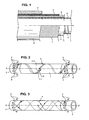
- Figure 4 shows a filament winding constituting the reinforcement layer and covering the entire surface of the pipe.
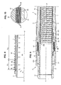
- Figure 5 is highly diagrammatic and shows the particular winding of a traction layer constituted by one or more filaments presenting winding pitch that differs depending on position along the axis of the pipe.
- the winding angle of the filament changes progressively from the value of 54.7° to a larger value, e.g. 65°. This increase in angle serves to provide good sealing at the connection with the liner, as described below.
- the winding pitch of the filament, referenced 41 passes to zero so as to go round the ends and continue winding around the body of the pipe.
- Figure 6 is a diagram for explaining how to calculate the force exerted on a filament from the pressure inside the pipe and the laying angle of the filament.
- Figure 7 is a projection onto a plane of a force F1 and of a force F2 exerted on a filament laid at an angle ⁇ 1 or ⁇ 2 respectively. This figure shows the influence of the laying angle.
- the laying angle of the filament increases so as to go from ⁇ 1 to ⁇ 2, the circumferential force increases going from Fc1 to Fc2. If these forces apply to a single filament, then the forces F1 and F2 have the same value but are oriented in different directions.
- Figure 8 shows an end fitting of a pipe in accordance with the invention subjected to an internal pressure P.
- the filament laying angle is 54.7°.
- the pipe In the zone Z3, the filament laying angle is 54.7°.
- the filament laying angle is 58°.
- the force Fc2 therein is greater than the force Fc1 by a ratio of 1.13.
- This force is sufficient to maintain excellent sealing between the liner and the end fitting without having recourse to external means such as clamping rings and/or bonding.
- the value of the axial force passes from Fa1 to Fa2 when the angle passes from ⁇ 1 to ⁇ 2.
- the difference between these two values is taken up by the adherence of the filament of its support, for example on rubber, at its location on the end fitting.
- the carcass 5, the liner 6, the reinforcement layer 7, and the cover 8 are preferably bonded to one another.
- the winding directions of the filaments in two adjacent layers are preferably reversed.
- the filaments 41 form circumferential windings that may also be covered by an additional winding of fibers 410, possibly having a mass of plastics or resin material overmolded thereon.
- the number and the dimensions of the pins 3 are naturally selected as a function of the characteristics required by the pipe, and in particular of the diameter of the filaments and the number of sheets implemented.
- the lashing members are not necessarily pins, nor are they necessarily cylindrical fingers; for example they could be constituted by hooks, teeth, and/or crenellations, in particular.
- the force exerted by the filaments on the lashing members is very low because of the "capstan effect". That is why said lashing members may have small dimensions.
- the lashing members are especially useful for guiding the filaments while they are being wound, during manufacturing of the flexible pipe. Once they have been suitably wound they may be simply fastened on the end fittings by means of glue, by embedding in resin or another bonding agent or by other means such as crimping.
- the lashing means such as the pins 3 could be removable.
- filaments could be inserted without play into radial receiving holes pierced in the end fitting before the manufacturing of the pipe, in order to facilitate the winding of the filament(s), and removed after the operations of winding and bonding (for example by gluing) the filament(s) on the end fittings.
- the filaments could even be severed at their locations on the end fittings, since the presence of the bonding means is sufficient to retain them and avoid slipping on the end fittings.
- the filaments may be circular in section, but that is not essential.
- They are made of a material presenting high traction strength.
- suitable materials mention can be made of synthetic materials, in particular aramid, and also carbon, glass, and steel. This includes nanometric fibers (for example carbon nanotubes).
- the filaments must be sufficiently fine and flexible to be capable of going round the lashing members, pins or other members, if any, as closely as possible, and to accept winding with varying pitch.
Landscapes
- Engineering & Computer Science (AREA)
- General Engineering & Computer Science (AREA)
- Mechanical Engineering (AREA)
- Rigid Pipes And Flexible Pipes (AREA)
Claims (11)
- Conduite flexible, comprenant une partie principale tubulaire cylindrique souple (1) reliée à chacune de ses extrémités à un embout connecteur rigide (2), en forme de manchon, la paroi de la partie principale étant renforcée mécaniquement par au moins une nappe de filaments de faible épaisseur (4) ayant une forte résistance à la traction, enroulés hélicoïdalement par rapport à l'axe longitudinal (X-X') de la conduite, lesdits filaments étant rattachés aux embouts connecteurs (2) au moyen d'organes d'amarrage prévus à leur périphérie et positionnés approximativement dans l'alignement des filaments, tels qu'un épaulement ou des picots (3) autour desquels les filaments passent et sont engagés, ladite nappe comprenant un réseau de filaments ininterrompus (4) reliant l'un à l'autre les deux embouts (2) alternativement dans une direction, puis dans l'autre, en contournant lesdits organes d'amarrage (3), tout en s'y accrochant, caractérisée par le fait que, d'une part, l'amarrage des filaments se fait de telle sorte qu'ils ne sont pas, ou pratiquement pas, écartés de l'enveloppe cylindrique dans laquelle s'inscrit la nappe et que d'autre part, l'angle (α) d'enroulement des filaments (4) par rapport aux génératrices au niveau des embouts d'extrémité (2) est supérieur à 54,7°, et avantageusement compris entre 56° et 65°, de sorte que, sous l'effet d'une pression interne régnant dans la conduite, la traction engendrée sur les filaments tend à resserrer les nappes sur la gaine d'étanchéité (6) et sur les embouts d'extrémité (2) et ainsi à améliorer, voire à assurer, l'étanchéité à ce niveau, ainsi que la fixation sur chaque embout.
- Conduite flexible selon la revendication 1, caractérisée par le fait que lesdits filaments sont rattachés aux embouts (2) au moyen d'un agent de liaison telle que de la colle ou de la résine dans laquelle les filaments sont noyés.
- Conduite flexible selon l'une des revendications 1 ou 2, caractérisée par le fait que lesdits filaments (4) ont une épaisseur inférieure à 4 mm et, de préférence, comprise entre 0,5 et 1mm.
- Conduite flexible selon la revendication 1 ou 2, caractérisée par le fait que lesdits filaments (4) sont en matière synthétique.
- Conduite flexible selon l'une des revendications 1 à 4, caractérisée par le fait que lesdits filaments (4) sont constitués d'une pluralité de fibres nanométriques.
- Conduite flexible selon l'une des revendications 1 à 5, caractérisée par le fait que l'angle (α) d'enroulement des filaments (4) par rapport aux génératrices, au moins dans la partie principale tubulaire (1) est de l'ordre de 55°.
- Conduite flexible selon l'une des revendications 1 à 6, caractérisée par le fait que le pas d'enroulement du réseau de filaments (4) est variable, plus faible au niveau des embouts d'extrémité (2) que dans la partie principale (1).
- Conduite flexible selon la revendication 7, dans laquelle les filaments (4) sont rattachés aux embouts (2) au moyen d'organes d'amarrage prévus à leur périphérie, tels qu'un ensemble de picots (3) et/ou un épaulement, caractérisée par le fait que ladite nappe s'étend légèrement au-delà desdits organes d'amarrage (3), vers les extrémités de la conduite, les filaments (4) étant enroulés circonférentiellement, ou approximativement circonférentiellement dans ces zones.
- Conduite flexible selon l'une des revendications précédentes, caractérisée par le fait qu'elle comporte plusieurs nappes concentriques de filaments (4) noyées dans une paroi (7) en matériau souple et élastique, par exemple en caoutchouc.
- Conduite flexible, comprenant une partie principale tubulaire cylindrique souple (1) reliée à chacune de ses extrémités à un embout connecteur rigide (2), en forme de manchon, la paroi de la partie principale comprenant, radialement de l'intérieur vers l'extérieur :a) une carcasse métallique flexible (5) ;b) une gaine d'étanchéité (6) en matière thermoplastique ou en élastomère ;c) une voûte de pression (7) composée de plusieurs nappes concentriques constituées de filaments (4) de faible épaisseur ayant une forte résistance à la traction, ces nappes étant incorporées dans une paroi en matériau souple et élastique, par exemple en caoutchouc ;d) une gaine de protection (8) en matière thermoplastique ou en élastomère ;caractérisée par le fait que, premièrement, les filaments (4) constitutifs de chaque nappe ont une épaisseur inférieure à 4 mm et sont enroulés hélicoïdalement par rapport à l'axe longitudinal (X-X') de la conduite, avec un pas variable, plus faible au niveau des embouts d'extrémité (2) que dans la partie principale (1), et que deuxièmement lesdits embouts sont pourvus à leur périphérie d'un ensemble d'organes d'amarrage (3), tels que des picots, positionnés dans l'alignement des filaments (4), chaque nappe comprenant un réseau de filaments ininterrompus reliant l'un à l'autre les deux embouts (2) alternativement dans une direction, puis dans l'autre, en contournant lesdits organes d'amarrage (3), tout en s'y accrochant.
- Conduite flexible selon la revendication 10, caractérisée par le fait que l'angle d'enroulement (α) des filaments (4) par rapport aux génératrices dans la partie principale tubulaire est de l'ordre de 55° tandis qu'au niveau des embouts d'extrémité il est compris entre 56° et 65°, de sorte que, sous l'effet d'une pression interne régnant dans la conduite, la traction engendrée sur les filaments tend à resserrer les nappes sur la gaine d'étanchéité (6) et sur les embouts d'extrémité (2) et ainsi à améliorer, ou à assurer l'étanchéité, de même que la fixation sur chaque embout, à ce niveau.
Applications Claiming Priority (2)
| Application Number | Priority Date | Filing Date | Title |
|---|---|---|---|
| FR0603048A FR2899665B1 (fr) | 2006-04-06 | 2006-04-06 | "conduite flexible a embouts d'extremite integres" |
| PCT/EP2006/063223 WO2007112785A1 (fr) | 2006-04-06 | 2006-06-14 | Tuyau flexible avec raccords d'extrémité intégrés |
Publications (2)
| Publication Number | Publication Date |
|---|---|
| EP2008010A1 EP2008010A1 (fr) | 2008-12-31 |
| EP2008010B1 true EP2008010B1 (fr) | 2012-10-24 |
Family
ID=37441529
Family Applications (1)
| Application Number | Title | Priority Date | Filing Date |
|---|---|---|---|
| EP06819044A Not-in-force EP2008010B1 (fr) | 2006-04-06 | 2006-06-14 | Tuyau flexible avec raccords d'extrémité intégrés |
Country Status (7)
| Country | Link |
|---|---|
| US (1) | US8302633B2 (fr) |
| EP (1) | EP2008010B1 (fr) |
| JP (1) | JP2009532637A (fr) |
| CN (1) | CN101415986B (fr) |
| FR (1) | FR2899665B1 (fr) |
| RU (1) | RU2397399C2 (fr) |
| WO (1) | WO2007112785A1 (fr) |
Families Citing this family (17)
| Publication number | Priority date | Publication date | Assignee | Title |
|---|---|---|---|---|
| FR2931920B1 (fr) | 2008-06-02 | 2010-09-17 | Saltel Ind | Conduite flexible a embouts d'extremite integres |
| CN111281266B (zh) * | 2011-04-29 | 2021-12-10 | 艾罗伯特公司 | 移动清洁机器人和自主覆盖机器人 |
| US20130118626A1 (en) * | 2011-11-15 | 2013-05-16 | Illinois Tool Works Inc. | Method of attaching a stiffening wire inside a flexible hose assembly |
| FR3008764B1 (fr) * | 2013-07-18 | 2015-09-04 | Technip France | Embout de connexion d'une conduite flexible, et conduite flexible associee |
| AU2014299014B2 (en) | 2013-08-02 | 2019-01-17 | National Oilwell Varco Denmark I/S | An unbonded flexible pipe and an offshore system comprising an unbonded flexible pipe |
| US20160312918A1 (en) * | 2015-04-21 | 2016-10-27 | Caterpillar Inc. | Hose Restraint System and Method for Using the Same |
| US9829131B2 (en) * | 2015-05-01 | 2017-11-28 | Pipelife Nederland B.V. | Pipe coupling construction, and coupling |
| WO2017023455A1 (fr) * | 2015-07-31 | 2017-02-09 | Kimberly-Clark Worldwide, Inc. | Appareil de bobinage de filament |
| CN105034412B (zh) * | 2015-08-25 | 2020-10-02 | 上海华渔新材料科技有限公司 | 一种高效抗疲劳复合材料与金属的连接接头及其连接方法 |
| KR102505855B1 (ko) * | 2016-01-11 | 2023-03-03 | 삼성전자 주식회사 | 가중치 기반 멀티-큐 가능 리소스 공유 방법 |
| CN105626979B (zh) * | 2016-02-05 | 2019-01-18 | 中联重科股份有限公司 | 输送系统、输送管及其制造方法 |
| GB2548825A (en) * | 2016-03-24 | 2017-10-04 | Magma Global Ltd | Pinned composite pipe end-fitting |
| EP3381668B1 (fr) * | 2017-03-31 | 2020-12-09 | Crompton Technology Group Limited | Arbre composite |
| WO2019225294A1 (fr) * | 2018-05-23 | 2019-11-28 | 三菱電機株式会社 | Structure de tuyau et structure en treillis, et satellite artificiel utilisant de telles structures |
| IT201900021978A1 (it) * | 2019-11-22 | 2021-05-22 | Fitt Spa | Tubo piatto flessibile realizzato in elastomero termoplastico per il trasporto di fluidi |
| CN111436892A (zh) * | 2020-05-14 | 2020-07-24 | 江苏工大博实医用机器人研究发展有限公司 | 一种医用柔性管状工具 |
| NL2025930B1 (en) * | 2020-06-26 | 2022-02-21 | Stichting Administratiekantoor Cra | Tubing for transporting a fluid, and methods of using the same |
Family Cites Families (12)
| Publication number | Priority date | Publication date | Assignee | Title |
|---|---|---|---|---|
| FR1166480A (fr) * | 1956-11-09 | 1958-11-12 | Kleber Colombes | Tuyau avec son dispositif de raccordement et procédé pour le fabriquer |
| US3232640A (en) * | 1960-09-14 | 1966-02-01 | Calumet & Hecla | Multi-wall flexible connector with interply pressurization |
| US4033612A (en) * | 1972-11-21 | 1977-07-05 | Institut Francais Du Petrole, Des Carburants Et Lubrifiants | Armored flexible pipe equipped with a rigid coupling |
| GB1584151A (en) * | 1976-04-15 | 1981-02-04 | Vredestein Nv | Highpressure filament reinforced hose having integral filament-bound couplings and method of making same |
| NL8600275A (nl) * | 1986-02-05 | 1987-09-01 | Vredestein Icopro Bv | Hoge-drukslang. |
| FR2675563B1 (fr) * | 1991-04-22 | 1993-08-27 | Aerospatiale | Procede d'assemblage mecanique d'un tube en materiau composite et d'une piece metallique et assemblage ainsi realise. |
| DK1023553T3 (da) | 1997-10-14 | 2002-04-15 | Nkt Flexibles Is | Samling af en endefitting og et fleksibel rør |
| CN2371414Y (zh) * | 1998-11-26 | 2000-03-29 | 程锦 | 耐压胶管 |
| JP4213910B2 (ja) * | 2002-05-24 | 2009-01-28 | 株式会社ブリヂストン | 給水給湯用ホース |
| EP1579141B1 (fr) * | 2002-11-29 | 2011-08-17 | NKT Flexibles I/S | Conduite flexible reliee a une piece d'extremite |
| RU50274U1 (ru) * | 2005-07-04 | 2005-12-27 | Общество с ограниченной ответственностью "Реммаш-Сервис" | Гибкая труба и концевое соединение гибкой трубы |
| RU2315223C1 (ru) * | 2006-04-13 | 2008-01-20 | ООО "Промтехнологии" | Гибкая грузонесущая полимерная труба и способ ее использования |
-
2006
- 2006-04-06 FR FR0603048A patent/FR2899665B1/fr not_active Expired - Fee Related
- 2006-06-14 JP JP2009503428A patent/JP2009532637A/ja not_active Withdrawn
- 2006-06-14 US US12/226,098 patent/US8302633B2/en not_active Expired - Fee Related
- 2006-06-14 WO PCT/EP2006/063223 patent/WO2007112785A1/fr not_active Ceased
- 2006-06-14 RU RU2008139154/06A patent/RU2397399C2/ru not_active IP Right Cessation
- 2006-06-14 EP EP06819044A patent/EP2008010B1/fr not_active Not-in-force
- 2006-06-14 CN CN2006800541203A patent/CN101415986B/zh not_active Expired - Fee Related
Also Published As
| Publication number | Publication date |
|---|---|
| CN101415986B (zh) | 2010-06-23 |
| RU2008139154A (ru) | 2010-05-20 |
| EP2008010A1 (fr) | 2008-12-31 |
| FR2899665A1 (fr) | 2007-10-12 |
| US20090309356A1 (en) | 2009-12-17 |
| US8302633B2 (en) | 2012-11-06 |
| CN101415986A (zh) | 2009-04-22 |
| WO2007112785A1 (fr) | 2007-10-11 |
| JP2009532637A (ja) | 2009-09-10 |
| FR2899665B1 (fr) | 2010-09-10 |
| RU2397399C2 (ru) | 2010-08-20 |
Similar Documents
| Publication | Publication Date | Title |
|---|---|---|
| EP2008010B1 (fr) | Tuyau flexible avec raccords d'extrémité intégrés | |
| US10935168B2 (en) | Spoolable reinforced thermoplastic pipe for subsea and buried applications | |
| EP0792429B1 (fr) | Ensemble raccord de tuyau composite renforce par fibres et soumis a des pressions elevees | |
| EP1592908B1 (fr) | Tuyau renforce de fibres | |
| US7243686B2 (en) | Hose | |
| CN102047019B (zh) | 具有内置端部件的软管 | |
| JP5746822B2 (ja) | 軸方向補強ホース | |
| US20200103059A1 (en) | Flexible pipe with layers of metal armour and layers of composite armour | |
| AU2007283195B2 (en) | Reinforced hose | |
| US7735524B2 (en) | Hose | |
| AU2001264075A1 (en) | Improvements relating to hose | |
| US6679298B2 (en) | Collapsible flexible pipe | |
| WO2000070256A1 (fr) | Conduit composite souple et leger pour huile et gaz sous haute pression | |
| AU2012252925B2 (en) | A flexible unbonded pipe | |
| EP1446603B1 (fr) | Conduite flexible a armature de traction | |
| CN113330240A (zh) | 海底环境中输送流体用软管和相关方法 | |
| AU2007200462A1 (en) | Improvements relating to hose |
Legal Events
| Date | Code | Title | Description |
|---|---|---|---|
| PUAI | Public reference made under article 153(3) epc to a published international application that has entered the european phase |
Free format text: ORIGINAL CODE: 0009012 |
|
| 17P | Request for examination filed |
Effective date: 20081104 |
|
| AK | Designated contracting states |
Kind code of ref document: A1 Designated state(s): AT BE BG CH CY CZ DE DK EE ES FI FR GB GR HU IE IS IT LI LT LU LV MC NL PL PT RO SE SI SK TR |
|
| AX | Request for extension of the european patent |
Extension state: AL BA HR MK RS |
|
| RAP1 | Party data changed (applicant data changed or rights of an application transferred) |
Owner name: SALTEL INDUSTRIES |
|
| 17Q | First examination report despatched |
Effective date: 20120215 |
|
| GRAP | Despatch of communication of intention to grant a patent |
Free format text: ORIGINAL CODE: EPIDOSNIGR1 |
|
| DAX | Request for extension of the european patent (deleted) | ||
| GRAS | Grant fee paid |
Free format text: ORIGINAL CODE: EPIDOSNIGR3 |
|
| GRAA | (expected) grant |
Free format text: ORIGINAL CODE: 0009210 |
|
| AK | Designated contracting states |
Kind code of ref document: B1 Designated state(s): AT BE BG CH CY CZ DE DK EE ES FI FR GB GR HU IE IS IT LI LT LU LV MC NL PL PT RO SE SI SK TR |
|
| REG | Reference to a national code |
Ref country code: GB Ref legal event code: FG4D |
|
| REG | Reference to a national code |
Ref country code: CH Ref legal event code: EP |
|
| REG | Reference to a national code |
Ref country code: AT Ref legal event code: REF Ref document number: 581147 Country of ref document: AT Kind code of ref document: T Effective date: 20121115 |
|
| REG | Reference to a national code |
Ref country code: IE Ref legal event code: FG4D |
|
| REG | Reference to a national code |
Ref country code: DE Ref legal event code: R096 Ref document number: 602006032699 Country of ref document: DE Effective date: 20121227 |
|
| REG | Reference to a national code |
Ref country code: DE Ref legal event code: R082 Ref document number: 602006032699 Country of ref document: DE Representative=s name: KILIAN KILIAN & PARTNER MBB PATENTANWAELTE, DE Ref country code: DE Ref legal event code: R082 Ref document number: 602006032699 Country of ref document: DE Representative=s name: KILIAN KILIAN & PARTNER, DE |
|
| REG | Reference to a national code |
Ref country code: AT Ref legal event code: MK05 Ref document number: 581147 Country of ref document: AT Kind code of ref document: T Effective date: 20121024 |
|
| REG | Reference to a national code |
Ref country code: NL Ref legal event code: VDEP Effective date: 20121024 |
|
| PG25 | Lapsed in a contracting state [announced via postgrant information from national office to epo] |
Ref country code: ES Free format text: LAPSE BECAUSE OF FAILURE TO SUBMIT A TRANSLATION OF THE DESCRIPTION OR TO PAY THE FEE WITHIN THE PRESCRIBED TIME-LIMIT Effective date: 20130204 Ref country code: IS Free format text: LAPSE BECAUSE OF FAILURE TO SUBMIT A TRANSLATION OF THE DESCRIPTION OR TO PAY THE FEE WITHIN THE PRESCRIBED TIME-LIMIT Effective date: 20130224 Ref country code: SE Free format text: LAPSE BECAUSE OF FAILURE TO SUBMIT A TRANSLATION OF THE DESCRIPTION OR TO PAY THE FEE WITHIN THE PRESCRIBED TIME-LIMIT Effective date: 20121024 Ref country code: NL Free format text: LAPSE BECAUSE OF FAILURE TO SUBMIT A TRANSLATION OF THE DESCRIPTION OR TO PAY THE FEE WITHIN THE PRESCRIBED TIME-LIMIT Effective date: 20121024 Ref country code: FI Free format text: LAPSE BECAUSE OF FAILURE TO SUBMIT A TRANSLATION OF THE DESCRIPTION OR TO PAY THE FEE WITHIN THE PRESCRIBED TIME-LIMIT Effective date: 20121024 |
|
| PG25 | Lapsed in a contracting state [announced via postgrant information from national office to epo] |
Ref country code: SI Free format text: LAPSE BECAUSE OF FAILURE TO SUBMIT A TRANSLATION OF THE DESCRIPTION OR TO PAY THE FEE WITHIN THE PRESCRIBED TIME-LIMIT Effective date: 20121024 Ref country code: BE Free format text: LAPSE BECAUSE OF FAILURE TO SUBMIT A TRANSLATION OF THE DESCRIPTION OR TO PAY THE FEE WITHIN THE PRESCRIBED TIME-LIMIT Effective date: 20121024 Ref country code: PT Free format text: LAPSE BECAUSE OF FAILURE TO SUBMIT A TRANSLATION OF THE DESCRIPTION OR TO PAY THE FEE WITHIN THE PRESCRIBED TIME-LIMIT Effective date: 20130225 Ref country code: CY Free format text: LAPSE BECAUSE OF FAILURE TO SUBMIT A TRANSLATION OF THE DESCRIPTION OR TO PAY THE FEE WITHIN THE PRESCRIBED TIME-LIMIT Effective date: 20121024 Ref country code: PL Free format text: LAPSE BECAUSE OF FAILURE TO SUBMIT A TRANSLATION OF THE DESCRIPTION OR TO PAY THE FEE WITHIN THE PRESCRIBED TIME-LIMIT Effective date: 20121024 Ref country code: LV Free format text: LAPSE BECAUSE OF FAILURE TO SUBMIT A TRANSLATION OF THE DESCRIPTION OR TO PAY THE FEE WITHIN THE PRESCRIBED TIME-LIMIT Effective date: 20121024 Ref country code: GR Free format text: LAPSE BECAUSE OF FAILURE TO SUBMIT A TRANSLATION OF THE DESCRIPTION OR TO PAY THE FEE WITHIN THE PRESCRIBED TIME-LIMIT Effective date: 20130125 |
|
| PG25 | Lapsed in a contracting state [announced via postgrant information from national office to epo] |
Ref country code: AT Free format text: LAPSE BECAUSE OF FAILURE TO SUBMIT A TRANSLATION OF THE DESCRIPTION OR TO PAY THE FEE WITHIN THE PRESCRIBED TIME-LIMIT Effective date: 20121024 |
|
| PG25 | Lapsed in a contracting state [announced via postgrant information from national office to epo] |
Ref country code: SK Free format text: LAPSE BECAUSE OF FAILURE TO SUBMIT A TRANSLATION OF THE DESCRIPTION OR TO PAY THE FEE WITHIN THE PRESCRIBED TIME-LIMIT Effective date: 20121024 Ref country code: CZ Free format text: LAPSE BECAUSE OF FAILURE TO SUBMIT A TRANSLATION OF THE DESCRIPTION OR TO PAY THE FEE WITHIN THE PRESCRIBED TIME-LIMIT Effective date: 20121024 Ref country code: DK Free format text: LAPSE BECAUSE OF FAILURE TO SUBMIT A TRANSLATION OF THE DESCRIPTION OR TO PAY THE FEE WITHIN THE PRESCRIBED TIME-LIMIT Effective date: 20121024 Ref country code: BG Free format text: LAPSE BECAUSE OF FAILURE TO SUBMIT A TRANSLATION OF THE DESCRIPTION OR TO PAY THE FEE WITHIN THE PRESCRIBED TIME-LIMIT Effective date: 20130124 Ref country code: EE Free format text: LAPSE BECAUSE OF FAILURE TO SUBMIT A TRANSLATION OF THE DESCRIPTION OR TO PAY THE FEE WITHIN THE PRESCRIBED TIME-LIMIT Effective date: 20121024 |
|
| PG25 | Lapsed in a contracting state [announced via postgrant information from national office to epo] |
Ref country code: RO Free format text: LAPSE BECAUSE OF FAILURE TO SUBMIT A TRANSLATION OF THE DESCRIPTION OR TO PAY THE FEE WITHIN THE PRESCRIBED TIME-LIMIT Effective date: 20121024 Ref country code: IT Free format text: LAPSE BECAUSE OF FAILURE TO SUBMIT A TRANSLATION OF THE DESCRIPTION OR TO PAY THE FEE WITHIN THE PRESCRIBED TIME-LIMIT Effective date: 20121024 |
|
| PLBE | No opposition filed within time limit |
Free format text: ORIGINAL CODE: 0009261 |
|
| STAA | Information on the status of an ep patent application or granted ep patent |
Free format text: STATUS: NO OPPOSITION FILED WITHIN TIME LIMIT |
|
| 26N | No opposition filed |
Effective date: 20130725 |
|
| REG | Reference to a national code |
Ref country code: DE Ref legal event code: R097 Ref document number: 602006032699 Country of ref document: DE Effective date: 20130725 |
|
| PG25 | Lapsed in a contracting state [announced via postgrant information from national office to epo] |
Ref country code: MC Free format text: LAPSE BECAUSE OF FAILURE TO SUBMIT A TRANSLATION OF THE DESCRIPTION OR TO PAY THE FEE WITHIN THE PRESCRIBED TIME-LIMIT Effective date: 20121024 |
|
| REG | Reference to a national code |
Ref country code: CH Ref legal event code: PL |
|
| REG | Reference to a national code |
Ref country code: IE Ref legal event code: MM4A |
|
| PG25 | Lapsed in a contracting state [announced via postgrant information from national office to epo] |
Ref country code: IE Free format text: LAPSE BECAUSE OF NON-PAYMENT OF DUE FEES Effective date: 20130614 Ref country code: CH Free format text: LAPSE BECAUSE OF NON-PAYMENT OF DUE FEES Effective date: 20130630 Ref country code: LI Free format text: LAPSE BECAUSE OF NON-PAYMENT OF DUE FEES Effective date: 20130630 |
|
| PG25 | Lapsed in a contracting state [announced via postgrant information from national office to epo] |
Ref country code: LT Free format text: LAPSE BECAUSE OF FAILURE TO SUBMIT A TRANSLATION OF THE DESCRIPTION OR TO PAY THE FEE WITHIN THE PRESCRIBED TIME-LIMIT Effective date: 20121024 |
|
| REG | Reference to a national code |
Ref country code: FR Ref legal event code: PLFP Year of fee payment: 10 |
|
| PG25 | Lapsed in a contracting state [announced via postgrant information from national office to epo] |
Ref country code: TR Free format text: LAPSE BECAUSE OF FAILURE TO SUBMIT A TRANSLATION OF THE DESCRIPTION OR TO PAY THE FEE WITHIN THE PRESCRIBED TIME-LIMIT Effective date: 20121024 |
|
| PG25 | Lapsed in a contracting state [announced via postgrant information from national office to epo] |
Ref country code: HU Free format text: LAPSE BECAUSE OF FAILURE TO SUBMIT A TRANSLATION OF THE DESCRIPTION OR TO PAY THE FEE WITHIN THE PRESCRIBED TIME-LIMIT; INVALID AB INITIO Effective date: 20060614 Ref country code: LU Free format text: LAPSE BECAUSE OF NON-PAYMENT OF DUE FEES Effective date: 20130614 |
|
| PGFP | Annual fee paid to national office [announced via postgrant information from national office to epo] |
Ref country code: DE Payment date: 20150612 Year of fee payment: 10 Ref country code: GB Payment date: 20150619 Year of fee payment: 10 |
|
| PGFP | Annual fee paid to national office [announced via postgrant information from national office to epo] |
Ref country code: FR Payment date: 20150615 Year of fee payment: 10 |
|
| REG | Reference to a national code |
Ref country code: DE Ref legal event code: R119 Ref document number: 602006032699 Country of ref document: DE |
|
| GBPC | Gb: european patent ceased through non-payment of renewal fee |
Effective date: 20160614 |
|
| REG | Reference to a national code |
Ref country code: FR Ref legal event code: ST Effective date: 20170228 |
|
| PG25 | Lapsed in a contracting state [announced via postgrant information from national office to epo] |
Ref country code: FR Free format text: LAPSE BECAUSE OF NON-PAYMENT OF DUE FEES Effective date: 20160630 Ref country code: DE Free format text: LAPSE BECAUSE OF NON-PAYMENT OF DUE FEES Effective date: 20170103 |
|
| PG25 | Lapsed in a contracting state [announced via postgrant information from national office to epo] |
Ref country code: GB Free format text: LAPSE BECAUSE OF NON-PAYMENT OF DUE FEES Effective date: 20160614 |