EP2008838B1 - Felgenkratzschutzvorrichtung für Schneeketten - Google Patents
Felgenkratzschutzvorrichtung für Schneeketten Download PDFInfo
- Publication number
- EP2008838B1 EP2008838B1 EP07425399A EP07425399A EP2008838B1 EP 2008838 B1 EP2008838 B1 EP 2008838B1 EP 07425399 A EP07425399 A EP 07425399A EP 07425399 A EP07425399 A EP 07425399A EP 2008838 B1 EP2008838 B1 EP 2008838B1
- Authority
- EP
- European Patent Office
- Prior art keywords
- guard element
- stud
- tang
- hole
- guard
- Prior art date
- Legal status (The legal status is an assumption and is not a legal conclusion. Google has not performed a legal analysis and makes no representation as to the accuracy of the status listed.)
- Active
Links
Images


Classifications
-
- B—PERFORMING OPERATIONS; TRANSPORTING
- B60—VEHICLES IN GENERAL
- B60C—VEHICLE TYRES; TYRE INFLATION; TYRE CHANGING; CONNECTING VALVES TO INFLATABLE ELASTIC BODIES IN GENERAL; DEVICES OR ARRANGEMENTS RELATED TO TYRES
- B60C27/00—Non-skid devices temporarily attachable to resilient tyres or resiliently-tyred wheels
- B60C27/06—Non-skid devices temporarily attachable to resilient tyres or resiliently-tyred wheels extending over the complete circumference of the tread, e.g. made of chains or cables
-
- B—PERFORMING OPERATIONS; TRANSPORTING
- B60—VEHICLES IN GENERAL
- B60C—VEHICLE TYRES; TYRE INFLATION; TYRE CHANGING; CONNECTING VALVES TO INFLATABLE ELASTIC BODIES IN GENERAL; DEVICES OR ARRANGEMENTS RELATED TO TYRES
- B60C27/00—Non-skid devices temporarily attachable to resilient tyres or resiliently-tyred wheels
- B60C27/006—Non-skid devices temporarily attachable to resilient tyres or resiliently-tyred wheels provided with protective parts, e.g. rubber elements to protect the rim portion
Definitions
- the present invention refers to a device for snow chains adapted to be mounted on the vehicle tyres and in particular to an anti-scratch device to avoid damaging the wheel rims of the tyres, because of rubbing against the metal elements of snow chains.
- Snow chains normally mounted on the drive wheels of the vehicle, bite into the snow and/or into the ice deposited on the road surface, increasing the friction on the tread and allowing a good road-holding by the vehicle's tyres.
- a snow chain generally consists of two side elements (chains, flexible cables, steel wires, ropes or the like), which in conditions of use are close in a ring on the side of the wheel facing towards the outside of the vehicle and on the side of the wheel facing towards the inside of the vehicle, which will be referred to hereunder as outer ring and inner ring.
- the inner ring and the outer ring are connected by a series of portions of chain variously arranged to create friction on the tread of the tyre, the whole being completed by a device for tensioning said elements, known as a tensioner.
- European patent EP 1.024.035 discloses a self-tensioning device in which one end of the outer ring of the snow chains is coupled to a no-return block and the other end comprises a free end portion. The end portion is passed through the no-return block, which allows traction thereof in only one direction and not in the opposite direction. In this manner, by pulling the end portion, it is possible to tension the chains and, once the terminal portion is released, the no-return block avoids slackening of the chains.
- All the elements that can come into contact with the wheel rim or with a wheel rim cover, such as the tensioning device and the end portion of the outer ring of the chain, are made of plastic material (or coated with plastic material) to prevent any rubbing against the wheel rim from causing a damage thereof, a drawback that is felt all the more in the case of alloy rims, which are normally more costly and delicate than the steel rims.
- European patent EP 1.621.368 discloses a no-return block for the chain-tensioning cable provided with an insert of soft material destined to come into contact with the wheel rim. This document shows the features of the preamble of claim 1.
- a guard device comprising a streamlined shell consisting of two plastic half-shells, which couple together enclosing within them the connecting hook and parts of the links of the portions of chain and of the links of the outer ring joined to the connecting hook.
- Object of the present invention is to overcome the abovementioned drawbacks by providing an anti-scratch device for snow chains that is able to avoid damages to the wheel rims and at the same time is reliable and adapted not to weaken the grip of the snow chains.
- Another object of the present invention is to provide such an anti-scratch device for snow chains that is cheap and easy to produce.
- Yet another object of the present invention is to provide such an anti-scratch device for snow chains that is practical and simple to mount.
- the anti-scratch device for snow chains comprises a first guard element comprising a stud provided with a tang adapted to be inserted into the connecting hook which joins a link of the outer ring to the portions of chain disposed transversally on the tyre, and a second guard element comprising a stud provided with a through hole within which engages the end of said tang of the first guard element.
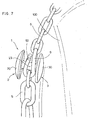
- the anti-scratch device for snow chains according to the invention designated as a whole with reference numeral 1 and illustrated in Figures 3 to 7 , is described with the aid of the figures.
- Figure 1 shows a vehicle wheel comprising a tyre 100 mounted on a wheel rim 101.
- a snow chain denoted as a whole with the reference numeral 4, is applied to the wheel as an anti/skid device.
- the chain 4 comprises:
- the portions of chain 6 are connected to the outer ring 5 by means of a special connecting hook 9.
- the connecting hook 9 is substantially shaped as a link of a chain and is obtained starting from a solid metal element with a circular section which is bent into a U-shape so as to obtain a first loop 90 which accommodates one or two end links of the portions of chain 6.
- the two end portions of the metal element bent into a U-shape are both bent into a U-shape so as to form other two loops 91 on parallel planes to each other and at right angles to the plane in which the first loop 90 is situated.
- the two loops 91 accommodate a link of the outer ring 5.
- the two ends 92 of the metal element forming the connecting hook 9 are situated at such a distance from the body of the connecting hook as to form a sufficiently narrow gap 93 to prevent the link of the outer ring 5 from coming out.
- one end 50 of the outer ring 5 is coupled to a no-return block 7 and the other end 51 thereof is connected to a chain terminal portion 52 which passes through the no-return block 7.
- the no-return block 7 allows the end portion 52 to slide in the chain tensioning direction (arrow F) and prevents the end portion 52 to slide in the chain slackening direction (arrow R).
- a self-tensioning block 8 - which contains an elastic cable 80 ending in a hook 81 destined to hook to the free end of the terminal portion 52 of the outer ring to tension it - is mounted in the outer ring 5.
- the self-tensioning block 8, the hook 81 of the elastic cable 80 and the end portion 52 of the outer ring 5 can also be made of plastic material or of any other suitable material to avoid possible damage to the wheel rim 101, following rubbing against said elements.
- the no-return block 7 is made of metal material, but inserts of soft material are applied thereto, as described in EP 1.621.368 .
- the connecting hook 9 for reasons of safety, must be made of metal material and its free ends 92 can be sharp. As a result, the continual rubbing of the connecting hook 9 and in particular of the sharp ends 92 thereof against the wheel rim 101 causes damage to said rim.
- an anti-scratch device has been devised according to the invention.
- the anti-scratch device 1 comprises two guard elements 2 and 3, made of a soft material such as plastic or rubber, which can be coupled to each other.
- the first guard element 2 comprises a substantially discoid shaped stud 20 having a rounded outer surface 21 in the shape of a spherical cap and a flat inner surface 22.
- a cylindrical tang or pin 23 integral with the stud 20 axially protrudes from the inner surface 22 of the stud 20.
- the tang 23 is provided with a smaller diameter portion or annular groove 24 which defines two radial abutment surfaces 26 and 27.
- the tang 23 ends in a truncated conical end part 28.
- the second guard element 3 comprises a substantially discoid shaped stud 30 having a rounded outer surface 31 in the form of a spherical cap and a flat inner surface 32.
- a though hole 33 is made axially in the stud 30.
- the hole 33 comprises a smaller diameter hole 34 towards the flat inner surface 32 and a larger diameter hole 35 towards the rounded outer surface 31.
- Between the two holes 34 and 35 is defined a radial abutment surface 36.
- the smaller diameter hole 34 has a slightly smaller diameter than the larger diameter of the truncated conical end part 28 of the tang 23.
- the two studs 20 and 30 have substantially the same dimensions, that is a diameter of about 18-22 mm so as to develop a large enough circular surface to cover at least partially the connecting hook 9.
- the tang 23 has a diameter of about 2-4 mm, small enough to be able to be inserted into the loop 90 of the connecting hook.
- the tang 23 has a length of about 15-20 mm so that its tapered end 28 can protrude outward from the connecting hook 9 to engage in the hole 33 of the second guard element 3.
Landscapes
- Engineering & Computer Science (AREA)
- Mechanical Engineering (AREA)
- Tires In General (AREA)
- Cleaning Of Streets, Tracks, Or Beaches (AREA)
- Suspension Of Electric Lines Or Cables (AREA)
- Gears, Cams (AREA)
Claims (9)
- Kratzschutzvorrichtung (1) für Schneeketten, umfassend:- ein erstes Schutzelement (2), umfassend einen Knopf (20), der mit einem zylindrischen Schaft (23) bereitgestellt ist, und- ein zweites Schutzelement (3), umfassend einen Knopf (30),dadurch gekennzeichnet, dass der zylindrische Schaft (23) des ersten Schutzelements dazu ausgebildet ist, in den Verbindungshaken (9) eingesetzt zu werden, der ein Glied des äußeren Rings (5) mit den Abschnitten einer Kette (6) verbindet, die quer an dem Reifen (100) angeordnet sind, und dass in dem zweiten Knopf (30) des zweiten Schutzelements (3) ein Durchgangsloch (33) gebildet ist, in das das Ende (28) des zylindrischen Schafts (23) des ersten Schutzelements (2) eingreift.
- Vorrichtung (1) nach Anspruch 1, dadurch gekennzeichnet, dass der zylindrische Schaft (23) axial von dem Knopf (20) des ersten Schutzelements (2) absteht und dass das Loch (33) axial in dem Knopf (30) des zweiten Schutzelements (3) gebildet ist.
- Vorrichtung (1) nach Anspruch 1 oder 2, dadurch gekennzeichnet, dass der zylindrische Schaft (23) des ersten Schutzelements (2) in einem Presskopplungsverhältnis in der Art eines Schnappverschlusses in das Loch (33) des zweiten Schutzelements (3) eingreift.
- Vorrichtung (1) nach Anspruch 3, dadurch gekennzeichnet, dass der zylindrische Schaft (23) des ersten Schutzelements (2) einen Abschnitt mit kleinerem Durchmesser oder eine ringförmige Nut (24) aufweist, der/die zwischen zwei radialen Auflageflächen (26, 27) definiert ist.
- Vorrichtung (1) nach einem der Ansprüche 3 oder 4, dadurch gekennzeichnet, dass der zylindrische Schaft (23) des ersten Schutzelements (2) ein kegelstumpfes Ende (28) aufweist.
- Vorrichtung (1) nach einem der Ansprüche 3 bis 5, dadurch gekennzeichnet, dass das Loch (33) des zweiten Schutzelements (3) ein Loch mit kleinerem Durchmesser (34) und ein Loch mit größerem Durchmesser (35), koaxial zueinander aufweist, so dass eine radiale Auflagefläche (36) gebildet ist.
- Vorrichtung (1) nach einem der vorangehenden Ansprüche, dadurch gekennzeichnet, dass der Knopf (20, 30) des ersten und/oder des zweiten Schutzelements (2, 3) im Wesentlichen scheibenförmig ist, wobei die äußere abgerundete Oberfläche im Wesentlichen als sphärische Kappe geformt ist.
- Vorrichtung (1) nach einem der vorangehenden Ansprüche, dadurch gekennzeichnet, dass der Knopf (20, 30) des ersten und/oder des zweiten Schutzelements (2, 3) im Wesentlichen scheibenförmig geformt ist, mit einer im Wesentlichen flachen Innenfläche.
- Vorrichtung (1) nach einem der vorangehenden Ansprüche, dadurch gekennzeichnet, dass der Knopf (20, 30) des ersten und/oder des zweiten Schutzelements (2, 3) aus einem weichen Material, wie Kunststoff oder Gummi, besteht.
Priority Applications (5)
| Application Number | Priority Date | Filing Date | Title |
|---|---|---|---|
| DE602007002802T DE602007002802D1 (de) | 2007-06-28 | 2007-06-28 | Felgenkratzschutzvorrichtung für Schneeketten |
| PL07425399T PL2008838T3 (pl) | 2007-06-28 | 2007-06-28 | Urządzenie zapobiegające zadrapaniom felgi do łańcuchów śniegowych |
| EP07425399A EP2008838B1 (de) | 2007-06-28 | 2007-06-28 | Felgenkratzschutzvorrichtung für Schneeketten |
| AT07425399T ATE445509T1 (de) | 2007-06-28 | 2007-06-28 | Felgenkratzschutzvorrichtung für schneeketten |
| JP2008155565A JP5358127B2 (ja) | 2007-06-28 | 2008-06-13 | スノーチェーン用のホイールリムのアンチスクラッチ装置 |
Applications Claiming Priority (1)
| Application Number | Priority Date | Filing Date | Title |
|---|---|---|---|
| EP07425399A EP2008838B1 (de) | 2007-06-28 | 2007-06-28 | Felgenkratzschutzvorrichtung für Schneeketten |
Publications (2)
| Publication Number | Publication Date |
|---|---|
| EP2008838A1 EP2008838A1 (de) | 2008-12-31 |
| EP2008838B1 true EP2008838B1 (de) | 2009-10-14 |
Family
ID=38651281
Family Applications (1)
| Application Number | Title | Priority Date | Filing Date |
|---|---|---|---|
| EP07425399A Active EP2008838B1 (de) | 2007-06-28 | 2007-06-28 | Felgenkratzschutzvorrichtung für Schneeketten |
Country Status (5)
| Country | Link |
|---|---|
| EP (1) | EP2008838B1 (de) |
| JP (1) | JP5358127B2 (de) |
| AT (1) | ATE445509T1 (de) |
| DE (1) | DE602007002802D1 (de) |
| PL (1) | PL2008838T3 (de) |
Cited By (2)
| Publication number | Priority date | Publication date | Assignee | Title |
|---|---|---|---|---|
| US8522846B2 (en) | 2010-09-15 | 2013-09-03 | Pewag Schneeketten Gmbh & Co Kg | Antiskid chain with sidewall protection covers |
| DE102020203068A1 (de) | 2020-03-11 | 2021-09-16 | Rud Ketten Rieger & Dietz Gmbh U. Co. Kg | Felgenschutzvorrichtung für Reifenketten sowie Reifenkette mit einer derartigen Felgenschutzvorrichtung |
Families Citing this family (1)
| Publication number | Priority date | Publication date | Assignee | Title |
|---|---|---|---|---|
| JP2022021048A (ja) * | 2020-07-21 | 2022-02-02 | 株式会社カーメイト | 滑り止めチェーン用リムプロテクター |
Family Cites Families (7)
| Publication number | Priority date | Publication date | Assignee | Title |
|---|---|---|---|---|
| US1651439A (en) * | 1927-07-01 | 1927-12-06 | William J Boyer | Antiskid cross chain |
| US2340171A (en) * | 1939-07-03 | 1944-01-25 | Frederick G L Boyer | Method of making antiskid chains |
| DE1009512B (de) * | 1956-10-01 | 1957-05-29 | Eisen U Drahtwerk Erlau A G | Gleitschutzkettenstrang mit ungeschraenkten Kettengliedern |
| JP2000071728A (ja) * | 1998-08-27 | 2000-03-07 | Ottinger Regina | 車両の車輪外周部を保護する装置 |
| PT1024035E (pt) * | 1999-01-28 | 2003-12-31 | Konig Spa | Dispositivo de auto-tensionamento para correntes de neve |
| NL1024570C2 (nl) * | 2003-10-20 | 2005-04-22 | Puzo B V | Sneeuwketting alsmede onderdeel hiervoor. |
| DE602004004260T2 (de) * | 2004-07-29 | 2007-11-15 | Thule S.P.A. | Sperrvorrichtung für Schneeketten |
-
2007
- 2007-06-28 EP EP07425399A patent/EP2008838B1/de active Active
- 2007-06-28 AT AT07425399T patent/ATE445509T1/de active
- 2007-06-28 DE DE602007002802T patent/DE602007002802D1/de active Active
- 2007-06-28 PL PL07425399T patent/PL2008838T3/pl unknown
-
2008
- 2008-06-13 JP JP2008155565A patent/JP5358127B2/ja active Active
Cited By (2)
| Publication number | Priority date | Publication date | Assignee | Title |
|---|---|---|---|---|
| US8522846B2 (en) | 2010-09-15 | 2013-09-03 | Pewag Schneeketten Gmbh & Co Kg | Antiskid chain with sidewall protection covers |
| DE102020203068A1 (de) | 2020-03-11 | 2021-09-16 | Rud Ketten Rieger & Dietz Gmbh U. Co. Kg | Felgenschutzvorrichtung für Reifenketten sowie Reifenkette mit einer derartigen Felgenschutzvorrichtung |
Also Published As
| Publication number | Publication date |
|---|---|
| EP2008838A1 (de) | 2008-12-31 |
| DE602007002802D1 (de) | 2009-11-26 |
| JP5358127B2 (ja) | 2013-12-04 |
| PL2008838T3 (pl) | 2010-03-31 |
| JP2009006998A (ja) | 2009-01-15 |
| ATE445509T1 (de) | 2009-10-15 |
Similar Documents
| Publication | Publication Date | Title |
|---|---|---|
| US6089291A (en) | Self-tensioning device for snow chains | |
| JP2010070186A (ja) | リム保護カバーを有する滑り止めチェーン | |
| CA1155376A (en) | Belt attachment for tire chains | |
| EP1621368B1 (de) | Sperrvorrichtung für Schneeketten | |
| US7472731B2 (en) | Snow chains with a limited bulk | |
| EP2008838A1 (de) | Felgenkratzschutzvorrichtung für Schneeketten | |
| US4280545A (en) | Wire rope traction device for tires | |
| EP0298697B1 (de) | Befestigungsvorrichtung für eine Reifenmatte | |
| EP1803591B1 (de) | System zur Befestigung eines Kettenstrangs an den Innenstrang einer Gleitschutzkette mit geringer Bauhöhe | |
| EP1072448B1 (de) | Automatische Spannvorrichtung für Schneeketten | |
| EP1737685B1 (de) | Befestigbares reifentraktionssystem | |
| EP1160102B1 (de) | Verbindungshaken um Elemente von Reifenketten zu verbinden | |
| US5899536A (en) | Tire chain wrapper | |
| CA1122108A (en) | Wire rope traction device for tires | |
| KR200270504Y1 (ko) | 타이어 미끄럼 방지장치의 결합부 | |
| KR200393274Y1 (ko) | 타이어 미끄럼 방지장치 | |
| JP4920676B2 (ja) | 弾性締結手段を含むタイヤチェーン取付システム | |
| KR200315444Y1 (ko) | 이륜자동차용 벨트형 미끄럼방지 장치 | |
| JPH0611202Y2 (ja) | タイヤ滑止具の連結具 | |
| US1369546A (en) | Tire-chain fastener | |
| JPH07205622A (ja) | タイヤチェーン | |
| KR20030062521A (ko) | 타이어 미끄럼 방지장치 |
Legal Events
| Date | Code | Title | Description |
|---|---|---|---|
| PUAI | Public reference made under article 153(3) epc to a published international application that has entered the european phase |
Free format text: ORIGINAL CODE: 0009012 |
|
| 17P | Request for examination filed |
Effective date: 20080131 |
|
| AK | Designated contracting states |
Kind code of ref document: A1 Designated state(s): AT BE BG CH CY CZ DE DK EE ES FI FR GB GR HU IE IS IT LI LT LU LV MC MT NL PL PT RO SE SI SK TR |
|
| AX | Request for extension of the european patent |
Extension state: AL BA HR MK RS |
|
| GRAP | Despatch of communication of intention to grant a patent |
Free format text: ORIGINAL CODE: EPIDOSNIGR1 |
|
| GRAS | Grant fee paid |
Free format text: ORIGINAL CODE: EPIDOSNIGR3 |
|
| AKX | Designation fees paid |
Designated state(s): AT CH DE FR IT LI PL |
|
| GRAA | (expected) grant |
Free format text: ORIGINAL CODE: 0009210 |
|
| AK | Designated contracting states |
Kind code of ref document: B1 Designated state(s): AT CH DE FR IT LI PL |
|
| REG | Reference to a national code |
Ref country code: CH Ref legal event code: EP |
|
| REF | Corresponds to: |
Ref document number: 602007002802 Country of ref document: DE Date of ref document: 20091126 Kind code of ref document: P |
|
| REG | Reference to a national code |
Ref country code: DE Ref legal event code: R096 Ref document number: 602007002802 Country of ref document: DE Effective date: 20091126 |
|
| REG | Reference to a national code |
Ref country code: PL Ref legal event code: T3 |
|
| PLBE | No opposition filed within time limit |
Free format text: ORIGINAL CODE: 0009261 |
|
| STAA | Information on the status of an ep patent application or granted ep patent |
Free format text: STATUS: NO OPPOSITION FILED WITHIN TIME LIMIT |
|
| 26N | No opposition filed |
Effective date: 20100715 |
|
| REG | Reference to a national code |
Ref country code: DE Ref legal event code: R097 Ref document number: 602007002802 Country of ref document: DE Effective date: 20100714 |
|
| PG25 | Lapsed in a contracting state [announced via postgrant information from national office to epo] |
Ref country code: IT Free format text: LAPSE BECAUSE OF NON-PAYMENT OF DUE FEES Effective date: 20100628 |
|
| REG | Reference to a national code |
Ref country code: FR Ref legal event code: PLFP Year of fee payment: 9 |
|
| PGFP | Annual fee paid to national office [announced via postgrant information from national office to epo] |
Ref country code: CH Payment date: 20150612 Year of fee payment: 9 |
|
| PGFP | Annual fee paid to national office [announced via postgrant information from national office to epo] |
Ref country code: PL Payment date: 20150513 Year of fee payment: 9 |
|
| REG | Reference to a national code |
Ref country code: CH Ref legal event code: PFA Owner name: KOENIG S.P.A., IT Free format text: FORMER OWNER: THULE S.P.A., IT |
|
| REG | Reference to a national code |
Ref country code: FR Ref legal event code: PLFP Year of fee payment: 10 |
|
| PGFP | Annual fee paid to national office [announced via postgrant information from national office to epo] |
Ref country code: AT Payment date: 20160628 Year of fee payment: 10 |
|
| REG | Reference to a national code |
Ref country code: CH Ref legal event code: PL |
|
| PG25 | Lapsed in a contracting state [announced via postgrant information from national office to epo] |
Ref country code: LI Free format text: LAPSE BECAUSE OF NON-PAYMENT OF DUE FEES Effective date: 20160630 Ref country code: CH Free format text: LAPSE BECAUSE OF NON-PAYMENT OF DUE FEES Effective date: 20160630 |
|
| REG | Reference to a national code |
Ref country code: FR Ref legal event code: PLFP Year of fee payment: 11 |
|
| REG | Reference to a national code |
Ref country code: AT Ref legal event code: MM01 Ref document number: 445509 Country of ref document: AT Kind code of ref document: T Effective date: 20170628 |
|
| PG25 | Lapsed in a contracting state [announced via postgrant information from national office to epo] |
Ref country code: PL Free format text: LAPSE BECAUSE OF NON-PAYMENT OF DUE FEES Effective date: 20160628 |
|
| PG25 | Lapsed in a contracting state [announced via postgrant information from national office to epo] |
Ref country code: AT Free format text: LAPSE BECAUSE OF NON-PAYMENT OF DUE FEES Effective date: 20170628 |
|
| REG | Reference to a national code |
Ref country code: FR Ref legal event code: PLFP Year of fee payment: 12 |
|
| REG | Reference to a national code |
Ref country code: DE Ref legal event code: R081 Ref document number: 602007002802 Country of ref document: DE Owner name: KONIG S.P.A., IT Free format text: FORMER OWNER: THULE S.P.A., MOLTENO, IT |
|
| PGFP | Annual fee paid to national office [announced via postgrant information from national office to epo] |
Ref country code: DE Payment date: 20250626 Year of fee payment: 19 |
|
| PGFP | Annual fee paid to national office [announced via postgrant information from national office to epo] |
Ref country code: FR Payment date: 20250620 Year of fee payment: 19 |
|
| PGFP | Annual fee paid to national office [announced via postgrant information from national office to epo] |
Ref country code: IT Payment date: 20250611 Year of fee payment: 19 |