EP2008914A2 - Revêtement pour pivot de fusée ou autre assemblage d'arbre - Google Patents
Revêtement pour pivot de fusée ou autre assemblage d'arbre Download PDFInfo
- Publication number
- EP2008914A2 EP2008914A2 EP08158828A EP08158828A EP2008914A2 EP 2008914 A2 EP2008914 A2 EP 2008914A2 EP 08158828 A EP08158828 A EP 08158828A EP 08158828 A EP08158828 A EP 08158828A EP 2008914 A2 EP2008914 A2 EP 2008914A2
- Authority
- EP
- European Patent Office
- Prior art keywords
- lubrication
- bearing
- inner ring
- shaft
- kingpin
- Prior art date
- Legal status (The legal status is an assumption and is not a legal conclusion. Google has not performed a legal analysis and makes no representation as to the accuracy of the status listed.)
- Withdrawn
Links
Images

Classifications
-
- F—MECHANICAL ENGINEERING; LIGHTING; HEATING; WEAPONS; BLASTING
- F16—ENGINEERING ELEMENTS AND UNITS; GENERAL MEASURES FOR PRODUCING AND MAINTAINING EFFECTIVE FUNCTIONING OF MACHINES OR INSTALLATIONS; THERMAL INSULATION IN GENERAL
- F16C—SHAFTS; FLEXIBLE SHAFTS; ELEMENTS OR CRANKSHAFT MECHANISMS; ROTARY BODIES OTHER THAN GEARING ELEMENTS; BEARINGS
- F16C33/00—Parts of bearings; Special methods for making bearings or parts thereof
- F16C33/30—Parts of ball or roller bearings
- F16C33/66—Special parts or details in view of lubrication
-
- B—PERFORMING OPERATIONS; TRANSPORTING
- B62—LAND VEHICLES FOR TRAVELLING OTHERWISE THAN ON RAILS
- B62D—MOTOR VEHICLES; TRAILERS
- B62D7/00—Steering linkage; Stub axles or their mountings
- B62D7/18—Steering knuckles; King pins
-
- F—MECHANICAL ENGINEERING; LIGHTING; HEATING; WEAPONS; BLASTING
- F16—ENGINEERING ELEMENTS AND UNITS; GENERAL MEASURES FOR PRODUCING AND MAINTAINING EFFECTIVE FUNCTIONING OF MACHINES OR INSTALLATIONS; THERMAL INSULATION IN GENERAL
- F16C—SHAFTS; FLEXIBLE SHAFTS; ELEMENTS OR CRANKSHAFT MECHANISMS; ROTARY BODIES OTHER THAN GEARING ELEMENTS; BEARINGS
- F16C23/00—Bearings for exclusively rotary movement adjustable for aligning or positioning
- F16C23/02—Sliding-contact bearings
- F16C23/04—Sliding-contact bearings self-adjusting
- F16C23/043—Sliding-contact bearings self-adjusting with spherical surfaces, e.g. spherical plain bearings
-
- F—MECHANICAL ENGINEERING; LIGHTING; HEATING; WEAPONS; BLASTING
- F16—ENGINEERING ELEMENTS AND UNITS; GENERAL MEASURES FOR PRODUCING AND MAINTAINING EFFECTIVE FUNCTIONING OF MACHINES OR INSTALLATIONS; THERMAL INSULATION IN GENERAL
- F16C—SHAFTS; FLEXIBLE SHAFTS; ELEMENTS OR CRANKSHAFT MECHANISMS; ROTARY BODIES OTHER THAN GEARING ELEMENTS; BEARINGS
- F16C33/00—Parts of bearings; Special methods for making bearings or parts thereof
- F16C33/02—Parts of sliding-contact bearings
- F16C33/04—Brasses; Bushes; Linings
- F16C33/06—Sliding surface mainly made of metal
- F16C33/10—Construction relative to lubrication
- F16C33/1025—Construction relative to lubrication with liquid, e.g. oil, as lubricant
- F16C33/106—Details of distribution or circulation inside the bearings, e.g. details of the bearing surfaces to affect flow or pressure of the liquid
- F16C33/1085—Channels or passages to recirculate the liquid in the bearing
-
- F—MECHANICAL ENGINEERING; LIGHTING; HEATING; WEAPONS; BLASTING
- F16—ENGINEERING ELEMENTS AND UNITS; GENERAL MEASURES FOR PRODUCING AND MAINTAINING EFFECTIVE FUNCTIONING OF MACHINES OR INSTALLATIONS; THERMAL INSULATION IN GENERAL
- F16C—SHAFTS; FLEXIBLE SHAFTS; ELEMENTS OR CRANKSHAFT MECHANISMS; ROTARY BODIES OTHER THAN GEARING ELEMENTS; BEARINGS
- F16C35/00—Rigid support of bearing units; Housings, e.g. caps, covers
-
- F—MECHANICAL ENGINEERING; LIGHTING; HEATING; WEAPONS; BLASTING
- F16—ENGINEERING ELEMENTS AND UNITS; GENERAL MEASURES FOR PRODUCING AND MAINTAINING EFFECTIVE FUNCTIONING OF MACHINES OR INSTALLATIONS; THERMAL INSULATION IN GENERAL
- F16C—SHAFTS; FLEXIBLE SHAFTS; ELEMENTS OR CRANKSHAFT MECHANISMS; ROTARY BODIES OTHER THAN GEARING ELEMENTS; BEARINGS
- F16C2326/00—Articles relating to transporting
- F16C2326/20—Land vehicles
- F16C2326/24—Steering systems, e.g. steering rods or columns
Definitions
- Single acting/angular contact spherical plain bearings are designed to support heavy unidirectional thrust and combination radial/thrust loads.
- such bearings comprise an inner ring and an outer ring, and the outer ring forms a concave spherical bearing surface that has a large bore opening and a small bore opening.
- the inner ring has a convex spherical bearing surface sized and configured to engage the outer ring bearing surface.
- the inner ring may have an interior shaft-engaging surface to engage a rotating and/or pivoting shaft therein.
- the outer ring bearing surface is symmetric about a central axis and increases in diameter from the small bore opening to the large bore opening. Accordingly, the inner ring is typically separable from the outer ring by removal via the large bore opening unless it is secured in the outer ring by an accessory structure.
- the outer ring typically has a lubrication groove in the concave interior bearing surface and a lubrication aperture that extends through the outer ring, from the exterior surface of the outer ring to the lubrication groove.
- the outer ring of the bearing is secured in a housing, and there is a housing lubrication aperture that communicates with the outer ring lubrication aperture.
- Lubricant can be injected into the bearing load zone (the interface of the bearing surfaces of the inner and outer rings) via the housing lubrication aperture and the outer ring lubrication aperture.
- the break-out groove communicates with the small bore opening of the outer ring.
- Lubricant may then be added to the load zone by injecting lubricant into to the small bore opening of the outer ring.
- the bearing may have a plate at the small bore opening to seal the opening and contain the lubricant provided via the outer ring lubrication aperture or via the shaft.
- a shaft in the bearing may be equipped with a lubrication aperture through which lubricant is supplied to the small bore opening. Using this configuration, the lubricant would flow through the shaft and deflect back into the bearing via the break-out groove.
- these methods of providing lubricant are sometimes ineffective due to the long and/or convoluted path of travel that the lubricant must traverse to reach the lubrication channel.
- the present invention resides in one aspect in a shaft and bearing assembly that includes a shaft mounted in a spherical plain bearing.
- the spherical plain bearing includes an outer ring and an inner ring disposed within the outer ring.
- the inner ring has a first bearing surface and an interior shaft-engaging surface, the first bearing surface having a convex spherical configuration.
- the inner ring is mounted on the shaft.
- the outer ring has a second bearing surface that engages the first bearing surface.
- the shaft comprises a shaft lubrication aperture that communicates with the inner ring lubrication aperture.
- the present invention resides in another aspect in a kingpin linkage assembly that includes a steering knuckle and an axle yoke pivotably interconnected with the steering knuckle by two kingpin-bearing assemblies.
- the kingpin-bearing assembly includes a kingpin and an associated spherical plain bearing.
- Each spherical plain bearing comprising an outer ring and an inner ring disposed within the outer ring, with the kingpin being mounted in the inner ring.
- the inner ring has a first bearing surface and an interior shaft-engaging surface, and the outer ring has a second bearing surface.
- the first bearing surface has a convex spherical configuration and the second bearing surface has a concave spherical configuration.
- the second bearing surface slidability engages the first bearing surface.
- the kingpin includes a kingpin lubrication aperture that communicates with the inner ring lubrication aperture.
- Another aspect of the invention resides in a method of lubricating a bearing and shaft assembly as described herein.
- the method includes flowing lubricant through the shaft lubrication aperture, through the inner ring lubrication aperture, and into the first lubrication groove.
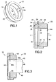
- Fig. 1 is a perspective view of an inner ring for a single acting spherical plain bearing as described herein;
- Fig. 2 is a schematic cross-sectional view of one embodiment of a spherical plain bearing according to the present invention
- Fig. 3 is a schematic cross-sectional view of the bearing of Fig 2 . with a shaft mounted therein;
- Fig. 4 is a schematic cross-sectional view of a kingpin linkage assembly comprising the bearing of Fig. 2 .
- Inner ring 10 has a first bearing surface 12 that has a convex, spherical configuration.
- the inner ring 10 also has an interior cylindrical shaft-engaging surface 14 that defines an inner ring bore 14a.
- Inner ring 10 also has an inner ring lubrication groove 16 on the first bearing surface 12 and an optional interior lubrication groove 18 on the shaft-engaging surface 14.
- the inner ring 10 is shown as having one inner ring lubrication groove 16, one interior lubrication groove 18 and two inner ring lubrication apertures 20, but the invention is not limited in this regard, as in alternative embodiments there may only be one inner ring lubrication aperture or there may be more than two such apertures. There may also be more than one inner ring lubrication groove 16 and/or more than one interior lubrication groove.
- a spherical plain bearing comprising the inner ring 10 of Fig. 1 is shown in Fig. 2 .
- the bearing 22 comprises the inner ring 10 and an outer ring 24.
- the outer ring 24 has a second bearing surface 26 that has a concave spherical configuration and is configured to have a large bore opening 28 on one side and a small bore opening 30 on the other side.
- the second bearing surface 26 is internal to the outer ring 24 and has a spherical configuration that is dimensioned to engage the first bearing surface 12 of the inner ring 10, which is disposed therein.
- the interface of the second bearing surface 26 and the first bearing surface 12 is the load zone of the bearing 22.
- the inner ring 10 and the outer ring 24 are both symmetric about respective central axes.
- Outer ring 24 has a outer ring lubrication groove 32 on the second bearing surface 26 and a lubrication outer ring lubrication aperture 34 that extends through the outer ring 24 and communicates with (e.g., opens to) the outer ring lubrication groove.
- An axially-oriented break-out lubrication groove 36 in the second bearing surface 26 that provides a flow path for lubrication to travel from the groove 32 to the small bore opening 30, thus providing lubricant communication between groove 32 and small bore opening 30.
- Outer ring 24 has an annular seat 38 at the small bore opening 30 where a sealing plate can be mounted to inhibit the loss of lubricant from the load zone through the small bore opening 30, and to inhibit the entry of contaminants into the bearing via the small bore opening.
- the outer ring 24 is shown as having one outer ring lubrication groove 32, one outer ring lubrication aperture and one optional break-out lubrication groove, but the invention is not limited in this regard, as in alternative embodiments there may only be more than one outer ring lubrication groove, and/or more than one outer ring lubrication aperture, and/or, optionally, more than one optional break-out lubrication groove.
- the bearing 22 provides a direct path for providing lubricant to the bearing load zone. This is accomplished by use of aperture 20 in the inner ring 10. Lubricant can be introduced into the bearing spherical raceway or load zone through a shaft mounted in inner ring 10, as described elsewhere herein.
- the shaft 40 has an exterior mounting surface 42 that engages the shaft-engaging surface 14 ( Fig. 1 ) of the inner ring 10.
- the shaft 40 has a shaft lubrication aperture 46 extending therethrough that includes a radial outlet 46a.
- the shaft 40 has on its surface 42 a circumferential lubrication groove 44 and, optionally, the radial outlet 46a opens to the circumferential lubrication groove.
- One or both of the radial outlet 46a and the lubrication groove 44 are aligned with the inner ring lubrication features, i.e., with aperture 20 and/or the inner ring lubrication groove 16, if the inner ring lubrication groove is present.
- This alignment allows the lubricant to flow through the shaft, through the inner ring lubrication aperture 20 and to one or more lubrication grooves, i.e., circumferential lubrication groove 44, inner ring lubrication groove 16 and/or the lubrication groove 32, to lubricate the load zone.
- a secondary lubricant flow path is provided via an axial lubrication outlet 46b.
- An optional seal plate 48 may be disposed in seat 38 ( Fig.
- a shaft 40 may have only a radial lubrication outlet, only an axial lubrication outlet, or more than two lubrication outlets.
- the load zone of the bearing 22 can be lubricated by injecting lubricant through an inner ring lubrication aperture 20, via the shaft lubrication aperture 46.
- Lubricant will flow through the shaft 40 and will enter the bearing via one or both of a radial lubrication outlet 46a and an axial lubrication outlet 46b.
- the lubricant will flow through the inner ring lubrication aperture 20 (optionally by way of the inner ring inner lubrication groove 18) to the load zone where it will be distributed via the inner ring lubrication groove 16 and/or the outer ring lubrication groove 32.
- the shaft may be a kingpin 56 or 58 ( Fig. 4 ), to provide a kingpin-and bearing assembly (unnumbered), and there may be two kingpin-and bearing assemblies in a kingpin linkage assembly 50 for a wheeled vehicle.
- the kingpin linkage assembly 50 comprises a steering knuckle 52 that is pivotably interconnected to an axle yoke 54 by the two kingpin-and bearing assemblies 39a, 39b.
- the steering knuckle 52 is connected to a wheel hub (not shown), while the axle yoke 54 is connected to an axle 55.
- the bearings 22 are mounted in respective mounting portions 54a, 54b of the axle yoke 54 and the outer rings 24 may be fixedly secured to the axle yoke.
- Each kingpin 56, 58 has a respective journal portion 56a, 58a that passes through a respective kingpin aperture 52a in the steering knuckle 52 and engages the bore 14a of the inner ring 10 of the associated bearing 22.
- the journal portions 56a, 58a include reduced diameter end portions that fit into the inner rings 10 of the respective bearings 22.
- the invention is not limited in this regard, and in the exercise of ordinary skill in the art, various sizes and configurations of journal portions on the kingpins can be matched with bearings.
- Each kingpin 56, 58 comprises a mounting portion 56b, 58b by which the kingpin is fixedly secured to the steering knuckle 52.
- each kingpin 56, 58 may have a respective head portion 56b, 58b that may be attached to the steering knuckle 52 by one or more bolts 60a, 60b that extend through the head portions to the steering knuckle.
- the invention is not limited in this regard as numerous other mounting configurations will occur to one of ordinary skill in the art, e.g., the kingpins 56 and/or 58 may have fitted portions 56c, 58c that are keyed in respective apertures in the steering knuckle 52.
- the kingpins 56, 58 may be equipped with lubrication apertures 62, 66 and lube fittings 64a, 64b to lubricate their respective bearings as described in relation to Fig. 3 .
- Kingpin 56 includes a radial lubrication outlet 62a and an axial lubrication outlet 62b.
- one or both of the kingpins 56, 58 may have a circumferential lubrication groove to which the radial lubrication outlet 62a opens.
- both kingpins 56 and 58 have a radial lubrication outlet 62a, 66a and an axial lubrication outlet 62b, 66b, but the invention is not limited in this regard as the kingpins 56, 58 need not have the same outlet configuration, and either or both of the kingpins 56, 58 may have either a radial lubrication outlet 56a, 66a or an axial lubrication outlet 56b, 66b.
- the outer rings 24 are installed in the axle yoke 54 and the inner rings 10 are pressed onto the kingpins 56, 58.
- the steering knuckle 52 is aligned with the axle yoke 54 and the kingpins (with inner rings 10 mounted thereon) are then inserted through the apertures 52a in the steering knuckle and into the axle yoke where the inner rings then mate with the outer rings 24.
- the assembly process is completed by bolting the kingpins 56, 58 to the steering knuckle 52 with bolts 60a, 60b.
- a driver rotates a steering wheel (not shown) that is connected to the steering knuckle 52 via tie rods (not shown).
- the kingpin linkage assembly allows the steering knuckle 52 and a wheel hub thereon to pivot relative to the axle yoke 54 and axle 55.
- the driver turns the vehicle wheels.
- Fig. 4 shows kingpin-bearing assemblies pivotably interconnecting an axle yoke and a steering knuckle wherein the kingpin is fixedly mounted in the steering knuckle and the bearing is mounted in the axle yoke
- the kingpins may be mounted on the axle yoke
- the bearings may be mounted in the steering knuckle.
- first do not denote any order, quantity, or importance, but rather are used to distinguish one element from another.
- a'' and “an” herein do not denote a limitation of quantity, but rather denote the presence of at least one of the referenced item.
Landscapes
- Engineering & Computer Science (AREA)
- General Engineering & Computer Science (AREA)
- Mechanical Engineering (AREA)
- Chemical & Material Sciences (AREA)
- Combustion & Propulsion (AREA)
- Transportation (AREA)
- Oil, Petroleum & Natural Gas (AREA)
- Steering-Linkage Mechanisms And Four-Wheel Steering (AREA)
- Support Of The Bearing (AREA)
- Sliding-Contact Bearings (AREA)
Applications Claiming Priority (1)
| Application Number | Priority Date | Filing Date | Title |
|---|---|---|---|
| US93740507P | 2007-06-26 | 2007-06-26 |
Publications (2)
| Publication Number | Publication Date |
|---|---|
| EP2008914A2 true EP2008914A2 (fr) | 2008-12-31 |
| EP2008914A3 EP2008914A3 (fr) | 2009-12-09 |
Family
ID=39777112
Family Applications (1)
| Application Number | Title | Priority Date | Filing Date |
|---|---|---|---|
| EP08158828A Withdrawn EP2008914A3 (fr) | 2007-06-26 | 2008-06-24 | Revêtement pour pivot de fusée ou autre assemblage d'arbre |
Country Status (8)
| Country | Link |
|---|---|
| US (1) | US20090003743A1 (fr) |
| EP (1) | EP2008914A3 (fr) |
| JP (1) | JP2009008261A (fr) |
| KR (1) | KR20080114547A (fr) |
| CN (1) | CN101429973A (fr) |
| CA (1) | CA2635578A1 (fr) |
| MX (1) | MX2008008293A (fr) |
| TW (1) | TW200916669A (fr) |
Cited By (2)
| Publication number | Priority date | Publication date | Assignee | Title |
|---|---|---|---|---|
| EP3539850A1 (fr) * | 2018-03-15 | 2019-09-18 | Gigant-Trenkamp & Gehle GmbH | Corps d'essieu doté d'un support de roue orientable relié au moyen d'une articulation tournante |
| EP3943367A1 (fr) * | 2020-07-24 | 2022-01-26 | Segway Technology Co., Ltd. | Structure de direction de véhicule et véhicule tout terrain |
Families Citing this family (10)
| Publication number | Priority date | Publication date | Assignee | Title |
|---|---|---|---|---|
| WO2011045350A1 (fr) * | 2009-10-15 | 2011-04-21 | Ford Global Technologies, Llc | Boîtier de mécanisme de direction en deux parties avec crémaillère dégagée |
| KR101415382B1 (ko) * | 2013-02-27 | 2014-07-04 | 쌍용자동차 주식회사 | 자동차용 이음 개선 베어링 어셈블리 |
| US10161460B2 (en) | 2013-05-21 | 2018-12-25 | Steering Solutions Ip Holding Corporation | Hot upset solid shaft sub-assembly |
| CN106050898A (zh) * | 2016-07-29 | 2016-10-26 | 青岛力克川液压机械有限公司 | 一种卡盘球铰小面积接触摩擦副结构 |
| CN109653973B (zh) * | 2018-11-17 | 2020-05-19 | 华中科技大学 | 一种水润滑轴阀复合配流的径向柱塞泵 |
| DE102019210006A1 (de) * | 2019-07-08 | 2021-01-14 | Aktiebolaget Skf | Gelenklager |
| CN114135577A (zh) * | 2021-12-13 | 2022-03-04 | 中国铁建重工集团股份有限公司 | 一种掘进机主轴承 |
| DE202022103859U1 (de) * | 2022-07-08 | 2023-10-18 | Dana Italia S.R.L. | Lenkgelenkanordnung |
| KR102809896B1 (ko) * | 2022-11-03 | 2025-05-22 | 현대위아 주식회사 | 서스펜션 액슬시스템 구조 |
| CN116557424A (zh) * | 2023-05-29 | 2023-08-08 | 山东福马轴承有限公司 | 一种自润滑关节轴承 |
Family Cites Families (22)
| Publication number | Priority date | Publication date | Assignee | Title |
|---|---|---|---|---|
| US1778391A (en) * | 1927-12-08 | 1930-10-14 | Kendall Edgar Homer | Bearing mounting |
| US2681259A (en) * | 1952-09-12 | 1954-06-15 | Torrington Co | Monoball self-aligning bushing |
| US2711352A (en) * | 1952-11-01 | 1955-06-21 | Hasko John | Spherical bearing |
| US2983555A (en) * | 1959-09-25 | 1961-05-09 | Hendrickson Mfg Co | Ball stud bearing assembly |
| US3243212A (en) * | 1962-11-16 | 1966-03-29 | Schaeffler Ohg Industriewerk | Ball and socket joint having an outer ring cracked radially |
| US3395951A (en) * | 1966-01-07 | 1968-08-06 | Roller Bearing Co Of America | Self-aligning bushing |
| US3479051A (en) * | 1968-01-11 | 1969-11-18 | Gen Motors Corp | Spherical bearing king pin steering knuckle assembly |
| US3464747A (en) * | 1968-03-12 | 1969-09-02 | Roller Bearing Co Of America | Self-aligning plain bearing |
| US4109976A (en) * | 1977-04-11 | 1978-08-29 | Roller Bearing Company Of America | Self-aligning bushing |
| DE3608782A1 (de) * | 1986-03-15 | 1987-09-24 | Thyssen Industrie | Drehgelenk mit durchstroemkanaelen |
| US4765757A (en) * | 1987-12-14 | 1988-08-23 | Roller Bearing Company Of America | Self-aligning spherical bushing means |
| JPH02114223U (fr) * | 1989-03-01 | 1990-09-12 | ||
| US4904106A (en) * | 1989-06-26 | 1990-02-27 | Dana Corporation | Socket bearing |
| GB2268982B (en) * | 1992-07-21 | 1996-03-13 | Dowty Aerospace Gloucester | Bearings |
| US5316332A (en) * | 1992-09-21 | 1994-05-31 | Thomas W. O'Rourke | Method and structure for correcting alignment of kingpin axle assemblies |
| US5772337A (en) * | 1997-05-01 | 1998-06-30 | Dana Corporation | Polywedge bearing for use with ball and socket |
| JP3462730B2 (ja) * | 1997-09-02 | 2003-11-05 | 三菱重工業株式会社 | 静圧軸受装置 |
| US5964325A (en) * | 1997-10-10 | 1999-10-12 | Dana Corporation | S-cam brake bushing cartridge |
| US20030035603A1 (en) * | 2001-08-15 | 2003-02-20 | V.W. Kaiser Engineering, Inc. | Thrust bushing for steering kingpin assembly |
| US6729763B2 (en) * | 2001-11-16 | 2004-05-04 | Kamatics Corporation | Hybrid bearing system |
| US7651274B2 (en) * | 2004-07-20 | 2010-01-26 | Komatsu Ltd. | Spherical slide bearing system |
| WO2008154343A2 (fr) * | 2007-06-06 | 2008-12-18 | Roller Bearing Company Of America, Inc. | Palier lisse sphérique à surface durcie |
-
2008
- 2008-04-22 US US12/107,300 patent/US20090003743A1/en not_active Abandoned
- 2008-06-23 MX MX2008008293A patent/MX2008008293A/es not_active Application Discontinuation
- 2008-06-23 CA CA002635578A patent/CA2635578A1/fr not_active Abandoned
- 2008-06-24 KR KR1020080059467A patent/KR20080114547A/ko not_active Ceased
- 2008-06-24 EP EP08158828A patent/EP2008914A3/fr not_active Withdrawn
- 2008-06-24 TW TW097123471A patent/TW200916669A/zh unknown
- 2008-06-25 JP JP2008165385A patent/JP2009008261A/ja active Pending
- 2008-06-26 CN CNA2008102154051A patent/CN101429973A/zh active Pending
Cited By (3)
| Publication number | Priority date | Publication date | Assignee | Title |
|---|---|---|---|---|
| EP3539850A1 (fr) * | 2018-03-15 | 2019-09-18 | Gigant-Trenkamp & Gehle GmbH | Corps d'essieu doté d'un support de roue orientable relié au moyen d'une articulation tournante |
| EP3943367A1 (fr) * | 2020-07-24 | 2022-01-26 | Segway Technology Co., Ltd. | Structure de direction de véhicule et véhicule tout terrain |
| US11851131B2 (en) | 2020-07-24 | 2023-12-26 | Segway Technology Co., Ltd. | Vehicle steering structure and all-terrain vehicle |
Also Published As
| Publication number | Publication date |
|---|---|
| JP2009008261A (ja) | 2009-01-15 |
| EP2008914A3 (fr) | 2009-12-09 |
| KR20080114547A (ko) | 2008-12-31 |
| CA2635578A1 (fr) | 2008-12-26 |
| TW200916669A (en) | 2009-04-16 |
| MX2008008293A (es) | 2009-03-04 |
| US20090003743A1 (en) | 2009-01-01 |
| CN101429973A (zh) | 2009-05-13 |
Similar Documents
| Publication | Publication Date | Title |
|---|---|---|
| EP2008914A2 (fr) | Revêtement pour pivot de fusée ou autre assemblage d'arbre | |
| US5722784A (en) | Kingpin Assembly | |
| KR100486471B1 (ko) | 주입성형부에 임베디드된 베어링 레이스를 갖는 휠마운팅 | |
| US9469165B2 (en) | Axle assembly having wheel hubs configured for use in vehicle with central tire inflation system | |
| US8783796B2 (en) | Pin for use in track rollers and bogie assemblies | |
| US8490986B1 (en) | Steering knuckle assembly having a kingpin | |
| US8939518B2 (en) | Tractor and trailer spindle assemblies | |
| US5281003A (en) | Bottom bracket axle assembly | |
| CN107922023B (zh) | 用于液压采矿铲履带的润滑芯筒 | |
| CN104228784A (zh) | 千斤顶组件 | |
| CA2670376C (fr) | Ensemble essieu directeur | |
| US6827359B2 (en) | Non-drive front axle steering knuckle | |
| JP2001524048A (ja) | 非駆動スティアリング可能な車輪用サスペンション | |
| DE3700564C2 (fr) | ||
| CA1310352C (fr) | Moyeu monobloc | |
| US7644999B2 (en) | Idler assembly, and method for retrofitting an existing idler assembly | |
| EP1513719B1 (fr) | Dispositif de suspension dirigeable de roue de vehicule | |
| US20090160151A1 (en) | A-arm frame with bearing for hauling devices | |
| US6663124B1 (en) | Co-axial kingpin lock mechanism | |
| EP3586022B1 (fr) | Ensemble palier et système de palier comprenant une telle ensemble palier | |
| JPH0627861Y2 (ja) | 圧延機用ロ−ルカツプリングにおける自動給脂構造 | |
| CN218577851U (zh) | 车桥组件和包括车桥组件的车辆 | |
| DE102023210571B4 (de) | Achsschenkelanordnung für ein Fahrzeug sowie Verfahren zur Herstellung der Achsschenkelanordnung | |
| CN120840304A (zh) | 一种车辆拖拽结构、使用方法及拖车 | |
| US10343474B2 (en) | Suspension bearing lubricating system |
Legal Events
| Date | Code | Title | Description |
|---|---|---|---|
| PUAI | Public reference made under article 153(3) epc to a published international application that has entered the european phase |
Free format text: ORIGINAL CODE: 0009012 |
|
| AK | Designated contracting states |
Kind code of ref document: A2 Designated state(s): AT BE BG CH CY CZ DE DK EE ES FI FR GB GR HR HU IE IS IT LI LT LU LV MC MT NL NO PL PT RO SE SI SK TR |
|
| AX | Request for extension of the european patent |
Extension state: AL BA MK RS |
|
| 17P | Request for examination filed |
Effective date: 20081223 |
|
| PUAL | Search report despatched |
Free format text: ORIGINAL CODE: 0009013 |
|
| AK | Designated contracting states |
Kind code of ref document: A3 Designated state(s): AT BE BG CH CY CZ DE DK EE ES FI FR GB GR HR HU IE IS IT LI LT LU LV MC MT NL NO PL PT RO SE SI SK TR |
|
| AX | Request for extension of the european patent |
Extension state: AL BA MK RS |
|
| RIC1 | Information provided on ipc code assigned before grant |
Ipc: F16C 33/10 20060101ALI20091102BHEP Ipc: B62D 7/18 20060101AFI20081006BHEP |
|
| 17Q | First examination report despatched |
Effective date: 20100702 |
|
| AKX | Designation fees paid |
Designated state(s): AT BE BG CH CY CZ DE DK EE ES FI FR GB GR HR HU IE IS IT LI LT LU LV MC MT NL NO PL PT RO SE SI SK TR |
|
| STAA | Information on the status of an ep patent application or granted ep patent |
Free format text: STATUS: THE APPLICATION IS DEEMED TO BE WITHDRAWN |
|
| 18D | Application deemed to be withdrawn |
Effective date: 20101113 |