EP2009194B1 - Cornière pour renforcer les angles et son procédé de fabrication - Google Patents
Cornière pour renforcer les angles et son procédé de fabrication Download PDFInfo
- Publication number
- EP2009194B1 EP2009194B1 EP07024314.2A EP07024314A EP2009194B1 EP 2009194 B1 EP2009194 B1 EP 2009194B1 EP 07024314 A EP07024314 A EP 07024314A EP 2009194 B1 EP2009194 B1 EP 2009194B1
- Authority
- EP
- European Patent Office
- Prior art keywords
- corner
- angle
- fabric mat
- angle profile
- profile
- Prior art date
- Legal status (The legal status is an assumption and is not a legal conclusion. Google has not performed a legal analysis and makes no representation as to the accuracy of the status listed.)
- Active
Links
Images



Classifications
-
- E—FIXED CONSTRUCTIONS
- E04—BUILDING
- E04F—FINISHING WORK ON BUILDINGS, e.g. STAIRS, FLOORS
- E04F13/00—Coverings or linings, e.g. for walls or ceilings
- E04F13/02—Coverings or linings, e.g. for walls or ceilings of plastic materials hardening after applying, e.g. plaster
- E04F13/04—Bases for plaster
- E04F13/06—Edge-protecting borders
-
- B—PERFORMING OPERATIONS; TRANSPORTING
- B29—WORKING OF PLASTICS; WORKING OF SUBSTANCES IN A PLASTIC STATE IN GENERAL
- B29C—SHAPING OR JOINING OF PLASTICS; SHAPING OF MATERIAL IN A PLASTIC STATE, NOT OTHERWISE PROVIDED FOR; AFTER-TREATMENT OF THE SHAPED PRODUCTS, e.g. REPAIRING
- B29C48/00—Extrusion moulding, i.e. expressing the moulding material through a die or nozzle which imparts the desired form; Apparatus therefor
- B29C48/03—Extrusion moulding, i.e. expressing the moulding material through a die or nozzle which imparts the desired form; Apparatus therefor characterised by the shape of the extruded material at extrusion
- B29C48/12—Articles with an irregular circumference when viewed in cross-section, e.g. window profiles
-
- E—FIXED CONSTRUCTIONS
- E04—BUILDING
- E04F—FINISHING WORK ON BUILDINGS, e.g. STAIRS, FLOORS
- E04F13/00—Coverings or linings, e.g. for walls or ceilings
- E04F13/02—Coverings or linings, e.g. for walls or ceilings of plastic materials hardening after applying, e.g. plaster
- E04F13/04—Bases for plaster
- E04F13/06—Edge-protecting borders
- E04F13/068—Edge-protecting borders combined with mesh material or the like to allow plaster to bond therewith
-
- B—PERFORMING OPERATIONS; TRANSPORTING
- B29—WORKING OF PLASTICS; WORKING OF SUBSTANCES IN A PLASTIC STATE IN GENERAL
- B29C—SHAPING OR JOINING OF PLASTICS; SHAPING OF MATERIAL IN A PLASTIC STATE, NOT OTHERWISE PROVIDED FOR; AFTER-TREATMENT OF THE SHAPED PRODUCTS, e.g. REPAIRING
- B29C48/00—Extrusion moulding, i.e. expressing the moulding material through a die or nozzle which imparts the desired form; Apparatus therefor
-
- B—PERFORMING OPERATIONS; TRANSPORTING
- B29—WORKING OF PLASTICS; WORKING OF SUBSTANCES IN A PLASTIC STATE IN GENERAL
- B29C—SHAPING OR JOINING OF PLASTICS; SHAPING OF MATERIAL IN A PLASTIC STATE, NOT OTHERWISE PROVIDED FOR; AFTER-TREATMENT OF THE SHAPED PRODUCTS, e.g. REPAIRING
- B29C48/00—Extrusion moulding, i.e. expressing the moulding material through a die or nozzle which imparts the desired form; Apparatus therefor
- B29C48/03—Extrusion moulding, i.e. expressing the moulding material through a die or nozzle which imparts the desired form; Apparatus therefor characterised by the shape of the extruded material at extrusion
- B29C48/07—Flat, e.g. panels
-
- E—FIXED CONSTRUCTIONS
- E04—BUILDING
- E04F—FINISHING WORK ON BUILDINGS, e.g. STAIRS, FLOORS
- E04F13/00—Coverings or linings, e.g. for walls or ceilings
- E04F13/02—Coverings or linings, e.g. for walls or ceilings of plastic materials hardening after applying, e.g. plaster
- E04F13/04—Bases for plaster
- E04F13/06—Edge-protecting borders
- E04F2013/063—Edge-protecting borders for corners
Definitions
- the invention relates to a corner angle for edge reinforcement with an angle section with two legs and with at least one fabric mat, which is connected to the angle section and protrudes beyond the legs thereof.
- the invention further relates to a method for producing a corner angle, in which an angle profile with two legs is connected to at least one fabric mat.
- corner brackets have long been known and serve the reinforcement of a plain wall bearing the visible plaster.
- the visible plaster can be applied to the outer thermal barrier coating or directly to the bricked or concrete building walls.
- corner angles are arranged in the corner areas on the outer wall or thermal insulation layer and incorporated into the plaster.
- Known corner angles have an angle profile, the legs of which enclose an angle of substantially 90 °.
- a fabric strip is attached, which protrudes beyond the free longitudinal edges of the legs, so as to provide the connection to a large-scale plaster reinforcement.
- the EP-A-0 915 215 describes a corner angle in which a fabric strip is secured by an anextruded draw strip on the angle section.
- Corner angles are exposed to high voltages when installed. Known corner angles, which allow a precise and secure corner design, are relatively complex in terms of construction and production.
- the GB 2 292 582 A describes a corner angle with an angle profile and a fabric mat disposed on the outside of the angle profile.
- a protective cap is fastened on the outside, so that the fabric mat is arranged in this area between the angle profile and the protective cap.
- the DE 100 60 619 A1 discloses a profile strip for plastering a wall or wall section or an insulating layer.
- a reinforcement fabric section may be fastened to the profile strip in that the reinforcement fabric section is clamped between a cover profile which is clipped onto the base body of the profile strip and the base body.
- the DE 34 30 614 A1 discloses a corner reinforcement having a reinforcing fabric strip and one or two further fabric strips as a corner reinforcement.
- From the DE 20 2006 015 852 U1 is a corner profile with a profile strip and an inside arranged on the profile strip mesh fabric strips known.
- the mesh fabric strip is attached with a dimensionally stable curable material on the profile strip.
- the DE 196 52 877 A1 discloses a cornice having two legs and an embedding fabric bonded to the insides of the legs by gluing, welding or the like.
- the EP 0 789 115 A1 discloses a Eckschwinkel with successive profile legs and with a reinforcing mat, which is connected to the inner sides of the profile legs.
- the reinforcement mat and the profile legs are welded together.
- the EP 1 514 978 A2 discloses a Einputzwinkel with trained as a corner molding profile and a fabric layer. The profile is extruded on both sides of the fabric layer.
- a terminal block for connecting a reinforcing fabric of a spatula adhesive layer with a door or window frame is in the DE 196 11 468 A1 disclosed.
- the invention is based on the finding that it is conducive to the most stable and reliable corner reinforcement if the corner angle itself is stably constructed and, in particular, withstands the stresses occurring in the plaster layer.
- a basic idea of the invention can be seen in enabling a particularly intimate connection of the fabric mat with a material layer lying below the corner angle.
- the material layer may for example consist of an adhesive or a mortar, with which the corner bracket is mounted on the outer thermal barrier coating of masonry. Due to the intimate connection of the fabric mat with the outer layer of material, the corner angle can be set particularly reliably at a corner.
- the fabric mat arranged on the inside on the angle profile Due to the fabric mat arranged on the inside on the angle profile, it is not released from the angle profile by stresses within a plaster layer to be applied to the corner angle. Such stresses occur because the outer layer of plaster is exposed to high temperature and weathering. In addition, enormous pressure and suction forces are created by wind loads on the plaster layer, which can cause a detachment of the fabric mat from the angle profile.
- the inside arrangement of the fabric mat on the angle profile causes in an advantageous manner that the fabric mat is largely protected from such stresses and forces.
- the fabric mat is embedded at a distance from the wall in the plaster layer.
- at least one leg has at least one bend or bend. This can also be designed as a paragraph. It is preferred that the bend or bend runs parallel to a corner region of the two legs and is designed such that it faces outward in the direction of the leg ends. As a result, the fabric mat is guided from an inner region of the plaster layer into an outer region. Tensile, shear and shear forces occurring in the plaster can thus be better absorbed.
- the kinking or bending is preferably constructed such that the fabric mat is guided in the installed state in an outer or upper third of the plaster layer.
- the fabric mat is not exposed outside, but protected inside the angle profile. As a result, it is protected during a Verputzvorganges from being released from the angle profile by the shear forces occurring during plastering. Damage or weakening of the fabric mat can be avoided.
- the corner angle according to the invention makes it possible, in a comparatively simple manner during plastering, to achieve a precise and defined outside corner, e.g. of 90 °. Due to the internal arrangement of the fabric mat, the outer edge of the corner angle is free from any interference with the fabric mat. The edge of the corner angle is thus particularly smooth and thereby allows the design of a precise and smooth outside corner with a straight edge course.
- a receiving space for receiving a part of the fabric mat is formed. This is open to the inside of the angle profile and according to a preferred embodiment, approximately U-shaped.
- the fabric mat is looped through this opening through the U-shaped receiving space.
- an open inner edge of the angle profile is achieved.
- a rounding of the inner edge of the angle profile is prevented by the fabric mat.
- the corner bracket can thus also be safely applied to a sharp-edged corner or edge become.
- the receiving space is particularly suitable in conjunction with a less flexible fabric mat.
- the receiving space is arranged in a bulge, which is designed as a trigger edge.
- a bulge which is designed as a trigger edge.
- a known pull-off edge for a plaster layer to be applied to the corner angle serves, in particular, to produce a defined rectilinear edge or corner.
- the trigger edge ensures improved shock protection.
- the arrangement of the receiving space within the trigger edge two elements of the corner angle are combined useful.
- the shape of the bulge can be chosen arbitrarily. However, it is particularly preferred that the bulge has an approximately U-shaped outer contour corresponding to the desired shape of the corner.
- the stability of the corner angle according to the invention is improved by the fact that the receiving space for fixing the fabric mat has at least one projection. Weathering or temperature fluctuations can cause tensions not only in the plaster layer but also in the building corner. These can be transferred to the fabric mat. In order to improve the fixation of the fabric mat with the angle profile by positive engagement, it can therefore engage in the hook-shaped projections. Since the greatest stresses occur directly in the corner of a wall, it is particularly advantageous to provide the hook-shaped projections within the receiving space.
- the receiving space is provided with the tissue mat used with a filling element.
- the fabric mat is materially and / or positively connected to the angle profile.
- the fixation is particularly firm.
- the receiving space is constricted inwards.
- the filling element comprises an extruded material, in particular hard or soft PVC.
- the filling element may in particular be formed from the same material as the angle profile or from another material. A particularly intimate connection of the filling element with both the angle profile and with the fabric mat can be achieved in that the filling element is coextruded with the angle profile.
- the filling element is a prefabricated strip of material. This can be a solid profile strip, such as a PVC strip, or a string. To fix the fabric mat, the material strip is pressed into the receiving space.
- a further improvement of the connection of the fabric mat with the angle profile is achieved in that the fabric mat is fixed to the legs of the angle profile, in particular glued. As a result, an additional stability of the corner profile is achieved.
- the legs of the angle profile have holes.
- the holes provide a connection or mediation between the surface on which the angle profile is placed, and the applied plaster layer.
- an adhesive layer or filler can pass through the holes from the inside to the outside and plaster from outside to inside, whereby the corner angle particularly is securely fixed.
- a development of the corner angle according to the invention is given by the fact that the angle section has an extruded material.
- the production of the angle profile from an extruded material makes the corner angle particularly economical.
- An angle profile made of an extruded material is particularly preferred if the filling element also has an extrudable material.
- the surface of the outer side of the angle profile by structuring, in particular profiling in the form of longitudinal grooves, is increased in order to achieve an even better clawing of the overlying plaster layer (plaster or mortar compound) with the angle profile. In this way can be made with reduced material use an equally stable angle profile. This leads to a reduction in production costs.
- the filling element may be a rigid bar or a flexible cord.
- the angle profile is produced in an extrusion process, that subsequently a part of the fabric mat is arranged in the receiving space and that the filling element is coextruded into the receiving space.
- the part of the fabric mat is introduced into the receiving space after the angle profile is cooled so far that it is dimensionally stable, but before it is completely cooled.
- the angle profile is reheated after inserting the fabric mat and then extruded the filling element in a pasty or molten state into the receiving space.
- the same device as for the extrusion of the angle profile can be used.
- a corner angle 10 is formed at least from an angle section 12 and a fabric mat 20.
- the angle section 12 has a first leg 13 and a second leg 14, which are arranged substantially at right angles to each other.
- the width of the legs 13 and 14 is about 2 to 3 cm.
- a trained as a trigger edge projection is arranged in the corner region of the two legs 13 and 14 .
- This is formed as a bulge 26, which forms a unit with the two legs 13 and 14.
- the bulge 26 has an approximately U-shaped cross section and has a correspondingly curved outer surface 27.
- a receiving space 24 is formed, through which the fabric mat 20 is guided in a loop-like manner.
- the fabric mat 20 essentially abuts against an inner surface of the bulge 26.
- the fabric mat 20 is filled with a filling element 30, in which the loop-like part of the fabric mat 20 is completely received or embedded.
- the filling element 30 was introduced into the receiving space 24 by means of coextrusion.
- the fabric mat 20 is also held by a hook-like projection 28 which is formed as an approximately triangular nose in the receiving space 24 in a form-fitting manner.
- the fabric mat 20 is bonded by an adhesive layer 34 on the inside of the first leg 13 of the angle section 12.
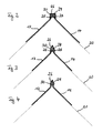
- Fig. 2 shows a further embodiment of the corner angle according to the invention 10.
- the bulge 26 as a U-profile formed with substantially angular edges. Inside the U-profile, a hook-like projection 28 is formed, which fixes the fabric mat.
- the in Fig. 3 Corner angle 10 shown has a bulge 26 which is arrow-shaped in cross section.
- the bulge 26 may also be referred to as a groove whose side walls run parallel and whose bottom portion forms a triangular tip.
- Hook-shaped projections 28 are formed on the two side walls.
- Fig. 4 shows a further alternative embodiment of a corner angle according to the invention 10.
- the cross section of the bulge 26 is in the form of an open at a tip parallelogram, in particular a rhombus formed. This shape is particularly suitable for use in conjunction with a solid profile strip as filling element 30, since the outer contour of the bulge 26 prevents detachment of the profile strip.
- a corner angle 10 is shown with a bulge 26 in the form of a three-quarter circle.
- a web 32 designed as a withdrawal edge is arranged on the outside.
- the web 32 is symmetrical to the two legs 13, 14 and has a tip in its end region, whose legs extend parallel to the legs 13, 14 of the angle section 12.
- the corner angle 10 off Fig. 6 has a triangular bulge 26. At the top of the triangular bulge 26, an outwardly facing web 32 is provided which extends symmetrically to both legs 13, 14 of the angle section 12.
- Fig. 7 shows in a schematic manner a perspective view of a corner angle according to the invention 10.
- the corner angle 10 as in Fig. 5 constructed corner angle shown.
- the legs 13, 14 have holes 16 to improve the fixation on an adhesive or filler layer.
- the angle profile 12 is provided with longitudinal grooves 22 in the region of the bulge 26 and the web 32.
- Fig. 8 essentially shows the in Fig. 7 Corner angle 10 shown, in which case the legs 13, 14 are provided with longitudinal grooves 22.
- Fig. 9 Shown schematically is a corner angle 10 with a plaster layer 40 applied thereon.
- the corner bracket 10 has a bulge 26 in the form of a three-quarter circle.
- a receiving space 24 is formed, which is filled with a filling element 30.
- On the outside of the bulge 26 a trained as a withdrawal wedge 36 web is arranged.
- a wedge-shaped edge runs parallel to the leg 14 of the angle profile 12.
- At the top of the withdrawal wedge 36 designed as a drip edge extension 38 is provided, which runs parallel to the leg 13 of the angle section 12.
- the extension 38 is used when applying a plaster layer 40 a correct removal of the plaster surface, for example with a smoothing trowel.
- the withdrawal wedge 36 serves in the same way the correct removal of the plaster surface on the leg 14.
- the drip edge serves to drain water quickly and clean, for example, from a balcony ceiling.
- Fig. 10 shows a corner angle 10, which is substantially the in Fig. 3 Corner angle corresponds to, with no projection 28 is provided.
- FIGS. 11 to 14 are variations of the in Fig. 10 shown corner angle 10, which relate to the configuration of the legs 13, 14 of the angle section 12.
- the two legs 13, 14 have a bend 18, the buckling edge in the longitudinal direction, that is parallel to the withdrawal edge formed as bulge 26 extends.
- the bend 18 serves to bring the tissue mat 20 resting against the inside of the legs 13, 14 into an outer area of a plaster layer 40.
- the fabric mat 20 is guided by the bend in an outer third of a plaster layer 40.
- the in Fig. 12 shown corner angle 10 has a bend 18, which compared to in Fig. 11 shown kinking flatter.
- the bend is S-shaped.
- a first, inner region of the legs 13, 14 extends parallel to a second, outer region of the legs 13, 14.
- the fabric mat 20 can be performed in an outer region of a plaster layer 40 in a particularly advantageous manner, wherein the fabric mat 20 in the plaster layer then again parallel to the legs 13, 14 or a plaster layer surface extends.
- a corner angle 10 is shown, which in each case has a Z-shaped bend 18 on the legs 13, 14. There are the same advantages as in the Fig. 13 Corner angle 10 shown.
- Fig. 15 shows a corner bracket 10 according to the prior art, in which a fabric mat 20 disposed on the outer surfaces of an angle section 12, in particular glued.
Landscapes
- Engineering & Computer Science (AREA)
- Architecture (AREA)
- Civil Engineering (AREA)
- Structural Engineering (AREA)
- Mechanical Engineering (AREA)
- Finishing Walls (AREA)
- Forms Removed On Construction Sites Or Auxiliary Members Thereof (AREA)
Claims (13)
- Cornière (10) pour renforcer les angles, avec- un profilé angulaire (12) à deux branches (13, 14) qui forment un angle l'une par rapport à l'autre et présentent plusieurs orifices (16) à travers lesquels une couche d'enduit à appliquer peut, depuis l'extérieur, parvenir à l'intérieur jusqu'à une surface sur laquelle le profilé angulaire peut être appliqué, et- au moins un textile (20) qui est placé à l'intérieur sur le profilé angulaire (12), est relié au profilé angulaire (12) et dépasse de ses branches (13, 14),caractérisée en ce que
dans la zone d'angle du profilé angulaire (12) est formé un logement (24) dans lequel est logée une partie du textile (20), et
en ce que le logement (24) avec le textile (20) inséré est muni d'un élément de remplissage (30) pour la fixation du tissu (20) sur le profilé angulaire (12). - Cornière (10) selon la revendication 1, caractérisée en ce qu'au moins une branche (13, 14) présente au moins un coude (18) ou un pliage.
- Cornière (10) selon la revendication 1 ou 2, caractérisée en ce que le logement (24) est réalisé approximativement en forme de U.
- Cornière (10) selon l'une des revendications 1 à 3, caractérisée en ce que le logement (24) est placé dans une partie bombée (26) qui est conformée en bord de lissage.
- Cornière (10) selon l'une des revendications 1 à 4, caractérisée en ce que le logement (24) présente au moins une saillie (28) pour la fixation du textile (20).
- Cornière (10) selon l'une des revendications 1 à 5, caractérisée en ce que l'élément de remplissage (30) présente un matériau extrudé, en particulier du PVC dur ou tendre.
- Cornière (10) selon l'une des revendications 1 à 6, caractérisée en ce que l'élément de remplissage (30) présente une bande de matière préfabriquée.
- Cornière (10) selon l'une des revendications 1 à 7, caractérisée en ce que le textile (20) est fixé, en particulier collé, sur les branches (13, 14) du profilé angulaire (12).
- Cornière (10) selon l'une des revendications 1 à 8, caractérisée en ce que le profilé angulaire (12) présente un matériau extrudé.
- Cornière (10) selon l'une des revendications 4 à 9, caractérisée en ce que la partie bombée (26) présente une barre (32) à l'extérieur.
- Cornière (10) selon la revendication 10, caractérisée en ce qu'un prolongement (38) conformé en larme est placé sur la barre (32).
- Cornière (10) selon l'une des revendications 1 à 11, caractérisée en ce que le profilé angulaire (12) a été fabriqué par un procédé d'extrusion et en ce que l'élément de remplissage (30) a été coextrudé dans le logement (24).
- Procédé de fabrication d'une cornière (10), en particulier selon l'une des revendications 1 à 12,
dans lequel un profilé angulaire (12) à deux branches (13, 14) est relié à au moins un textile (20) et le textile (20) est placé à l'intérieur sur le profilé angulaire (12),
caractérisé en ce que le profilé angulaire (12) est fabriqué par un procédé d'extrusion,
en ce qu'ensuite, une partie du textile (20) est placée dans un logement (24) formé dans la zone d'angle du profilé angulaire (12), et
en ce que le logement (24) avec le textile (20) inséré est muni d'un élément de remplissage (30), l'élément de remplissage (30) étant coextrudé à l'intérieur du logement (24).
Priority Applications (2)
| Application Number | Priority Date | Filing Date | Title |
|---|---|---|---|
| PL07024314T PL2009194T3 (pl) | 2007-06-28 | 2007-12-14 | Narożny kątownik do zbrojenia krawędzi i sposób jego wytwarzania |
| EP07024314.2A EP2009194B1 (fr) | 2007-06-28 | 2007-12-14 | Cornière pour renforcer les angles et son procédé de fabrication |
Applications Claiming Priority (2)
| Application Number | Priority Date | Filing Date | Title |
|---|---|---|---|
| EP07012736A EP2009193A1 (fr) | 2007-06-28 | 2007-06-28 | Cornière pour renforcer les angles et son procédé de fabrication |
| EP07024314.2A EP2009194B1 (fr) | 2007-06-28 | 2007-12-14 | Cornière pour renforcer les angles et son procédé de fabrication |
Publications (3)
| Publication Number | Publication Date |
|---|---|
| EP2009194A2 EP2009194A2 (fr) | 2008-12-31 |
| EP2009194A3 EP2009194A3 (fr) | 2011-03-02 |
| EP2009194B1 true EP2009194B1 (fr) | 2013-06-26 |
Family
ID=38662910
Family Applications (2)
| Application Number | Title | Priority Date | Filing Date |
|---|---|---|---|
| EP07012736A Withdrawn EP2009193A1 (fr) | 2007-06-28 | 2007-06-28 | Cornière pour renforcer les angles et son procédé de fabrication |
| EP07024314.2A Active EP2009194B1 (fr) | 2007-06-28 | 2007-12-14 | Cornière pour renforcer les angles et son procédé de fabrication |
Family Applications Before (1)
| Application Number | Title | Priority Date | Filing Date |
|---|---|---|---|
| EP07012736A Withdrawn EP2009193A1 (fr) | 2007-06-28 | 2007-06-28 | Cornière pour renforcer les angles et son procédé de fabrication |
Country Status (2)
| Country | Link |
|---|---|
| EP (2) | EP2009193A1 (fr) |
| PL (1) | PL2009194T3 (fr) |
Family Cites Families (10)
| Publication number | Priority date | Publication date | Assignee | Title |
|---|---|---|---|---|
| DE2641585A1 (de) * | 1976-09-16 | 1978-03-23 | Willi Bihl | Schutz-fuehrungsleiste fuer mauerecken |
| DE3430614A1 (de) * | 1983-08-19 | 1985-06-13 | Peter 7295 Dornstetten Halm | Kantenschutz-richtwinkel |
| GB2292582B (en) * | 1994-08-25 | 1997-08-27 | Trimtec Ltd | Render or plaster profile |
| DE29602293U1 (de) * | 1996-02-12 | 1996-05-09 | Protektorwerk Florenz Maisch GmbH & Co KG, 76571 Gaggenau | Eckschutzwinkel |
| DE29603185U1 (de) * | 1996-02-22 | 1996-04-11 | Frieser, Hartmut, 07356 Lobenstein | Gewebeeckleiste |
| DE19611468B4 (de) * | 1996-03-22 | 2009-03-05 | Silvan Becker | Anschlußleiste zur Verbindung eines Bewehrungs-Gewebes einer Spachtelkleberschicht mit einem Tür- oder Fensterrahmen |
| DE19747602A1 (de) * | 1997-10-28 | 1999-04-29 | Silvan Becker | Kantenschutz-Richtwinkel |
| DE10060619C2 (de) * | 2000-12-05 | 2003-12-04 | Konrad Lehrhuber | Profilleiste zum Verputzen |
| DE20314023U1 (de) | 2003-09-10 | 2003-11-13 | Wörner, Elisabeth, 72805 Lichtenstein | Einputzwinkel |
| DE202006015852U1 (de) * | 2006-10-17 | 2006-12-21 | Vws-Befestigungstechnik Gmbh | Gittergewebestreifen |
-
2007
- 2007-06-28 EP EP07012736A patent/EP2009193A1/fr not_active Withdrawn
- 2007-12-14 EP EP07024314.2A patent/EP2009194B1/fr active Active
- 2007-12-14 PL PL07024314T patent/PL2009194T3/pl unknown
Also Published As
| Publication number | Publication date |
|---|---|
| EP2009194A2 (fr) | 2008-12-31 |
| EP2009193A1 (fr) | 2008-12-31 |
| PL2009194T3 (pl) | 2013-10-31 |
| EP2009194A3 (fr) | 2011-03-02 |
Similar Documents
| Publication | Publication Date | Title |
|---|---|---|
| EP2404008B1 (fr) | Dispositif d'étanchéité sur un joint dans une construction | |
| DE20011013U1 (de) | Laibungsanschlußprofil | |
| EP1222346B1 (fr) | Baguette de limitation de crépi | |
| EP1627982B1 (fr) | Profilé de jonction | |
| DE10114233B4 (de) | Holz-Alu-Fenster | |
| DE10038279B4 (de) | Anordnungen von Putz-Eckleisten an einer Bauwerksecke | |
| EP0497320A1 (fr) | Dispositif pour former des arêtes suivant des saillies regulières, par exemple sur des bâtiments | |
| EP2093339B1 (fr) | Dispositif de fixation d'un joint sur une plaque de coffrage | |
| DE19747602A1 (de) | Kantenschutz-Richtwinkel | |
| DE102009004690B4 (de) | Anschlussprofilleiste, insbesondere Laibungsanschlussprofilleiste | |
| EP2009194A2 (fr) | Cornière pour renforcer les angles et son procédé de fabrication | |
| DE102010009376A1 (de) | Putzabschlussprofil und Verfahren zur Herstellung eines Anschlusses zwischen zwei Wänden | |
| EP2154303A2 (fr) | Profil de joint de dilatation destiné au recouvrement d'un joint de dilatation | |
| DE202009016212U1 (de) | Verkleidungselement für ein Außenmauerwerk | |
| EP2735666B1 (fr) | Système de profil de construction | |
| EP4036347B1 (fr) | Profilé d'enduit avec une feuille d'enduit sur l'un de ses pieds d'enduit | |
| EP1548197A1 (fr) | Dispositif et procédé pour l'étanchéification de joints de constructions, en particulier pour des joints d'expansion de façade | |
| AT528007B1 (de) | Anschlussprofil für an putz angrenzende bauteile mit selbstvernetzenden und/oder aushärtenden dichtmittel | |
| DE20210443U1 (de) | Einputzwinkel als Eckbewehrung | |
| EP3276100A1 (fr) | Système d'étanchéité pour un système de paroi | |
| DE102004026429B3 (de) | Fugenbandhalterung sowie Herstellungsverfahren für Betonierungsabschnitte | |
| DE102009036925A1 (de) | Verfahren zur Herstellung einer Gewebeprofilleiste | |
| DE202008011782U1 (de) | Kantenprofil und Sockelprofilsystem | |
| EP4571013A1 (fr) | Baguette d'étanchéité en plâtre | |
| DE202009013120U1 (de) | Einteilige Anputzleiste sowie Übergang zwischen zwei Bestandteilen eines Gebäudes |
Legal Events
| Date | Code | Title | Description |
|---|---|---|---|
| PUAI | Public reference made under article 153(3) epc to a published international application that has entered the european phase |
Free format text: ORIGINAL CODE: 0009012 |
|
| AK | Designated contracting states |
Kind code of ref document: A2 Designated state(s): AT BE BG CH CY CZ DE DK EE ES FI FR GB GR HU IE IS IT LI LT LU LV MC MT NL PL PT RO SE SI SK TR |
|
| AX | Request for extension of the european patent |
Extension state: AL BA HR MK RS |
|
| RAP1 | Party data changed (applicant data changed or rights of an application transferred) |
Owner name: WEROFORM GMBH |
|
| PUAL | Search report despatched |
Free format text: ORIGINAL CODE: 0009013 |
|
| AK | Designated contracting states |
Kind code of ref document: A3 Designated state(s): AT BE BG CH CY CZ DE DK EE ES FI FR GB GR HU IE IS IT LI LT LU LV MC MT NL PL PT RO SE SI SK TR |
|
| AX | Request for extension of the european patent |
Extension state: AL BA HR MK RS |
|
| 17P | Request for examination filed |
Effective date: 20110428 |
|
| AKX | Designation fees paid |
Designated state(s): AT BE BG CH CY CZ DE DK EE ES FI FR GB GR HU IE IS IT LI LT LU LV MC MT NL PL PT RO SE SI SK TR |
|
| GRAP | Despatch of communication of intention to grant a patent |
Free format text: ORIGINAL CODE: EPIDOSNIGR1 |
|
| GRAS | Grant fee paid |
Free format text: ORIGINAL CODE: EPIDOSNIGR3 |
|
| GRAA | (expected) grant |
Free format text: ORIGINAL CODE: 0009210 |
|
| AK | Designated contracting states |
Kind code of ref document: B1 Designated state(s): AT BE BG CH CY CZ DE DK EE ES FI FR GB GR HU IE IS IT LI LT LU LV MC MT NL PL PT RO SE SI SK TR |
|
| REG | Reference to a national code |
Ref country code: GB Ref legal event code: FG4D Free format text: NOT ENGLISH |
|
| REG | Reference to a national code |
Ref country code: CH Ref legal event code: EP |
|
| REG | Reference to a national code |
Ref country code: AT Ref legal event code: REF Ref document number: 618775 Country of ref document: AT Kind code of ref document: T Effective date: 20130715 |
|
| REG | Reference to a national code |
Ref country code: IE Ref legal event code: FG4D Free format text: LANGUAGE OF EP DOCUMENT: GERMAN |
|
| REG | Reference to a national code |
Ref country code: CH Ref legal event code: NV Representative=s name: BOGENSBERGER PATENT- AND MARKENBUERO DR. BURKH, LI |
|
| REG | Reference to a national code |
Ref country code: DE Ref legal event code: R096 Ref document number: 502007011945 Country of ref document: DE Effective date: 20130822 |
|
| PG25 | Lapsed in a contracting state [announced via postgrant information from national office to epo] |
Ref country code: SI Free format text: LAPSE BECAUSE OF FAILURE TO SUBMIT A TRANSLATION OF THE DESCRIPTION OR TO PAY THE FEE WITHIN THE PRESCRIBED TIME-LIMIT Effective date: 20130626 Ref country code: GR Free format text: LAPSE BECAUSE OF FAILURE TO SUBMIT A TRANSLATION OF THE DESCRIPTION OR TO PAY THE FEE WITHIN THE PRESCRIBED TIME-LIMIT Effective date: 20130927 Ref country code: LT Free format text: LAPSE BECAUSE OF FAILURE TO SUBMIT A TRANSLATION OF THE DESCRIPTION OR TO PAY THE FEE WITHIN THE PRESCRIBED TIME-LIMIT Effective date: 20130626 Ref country code: FI Free format text: LAPSE BECAUSE OF FAILURE TO SUBMIT A TRANSLATION OF THE DESCRIPTION OR TO PAY THE FEE WITHIN THE PRESCRIBED TIME-LIMIT Effective date: 20130626 Ref country code: SE Free format text: LAPSE BECAUSE OF FAILURE TO SUBMIT A TRANSLATION OF THE DESCRIPTION OR TO PAY THE FEE WITHIN THE PRESCRIBED TIME-LIMIT Effective date: 20130626 |
|
| REG | Reference to a national code |
Ref country code: PL Ref legal event code: T3 |
|
| REG | Reference to a national code |
Ref country code: LT Ref legal event code: MG4D |
|
| PG25 | Lapsed in a contracting state [announced via postgrant information from national office to epo] |
Ref country code: BG Free format text: LAPSE BECAUSE OF FAILURE TO SUBMIT A TRANSLATION OF THE DESCRIPTION OR TO PAY THE FEE WITHIN THE PRESCRIBED TIME-LIMIT Effective date: 20130926 |
|
| REG | Reference to a national code |
Ref country code: SK Ref legal event code: T3 Ref document number: E 14852 Country of ref document: SK |
|
| REG | Reference to a national code |
Ref country code: NL Ref legal event code: VDEP Effective date: 20130626 |
|
| PG25 | Lapsed in a contracting state [announced via postgrant information from national office to epo] |
Ref country code: LV Free format text: LAPSE BECAUSE OF FAILURE TO SUBMIT A TRANSLATION OF THE DESCRIPTION OR TO PAY THE FEE WITHIN THE PRESCRIBED TIME-LIMIT Effective date: 20130626 |
|
| PG25 | Lapsed in a contracting state [announced via postgrant information from national office to epo] |
Ref country code: EE Free format text: LAPSE BECAUSE OF FAILURE TO SUBMIT A TRANSLATION OF THE DESCRIPTION OR TO PAY THE FEE WITHIN THE PRESCRIBED TIME-LIMIT Effective date: 20130626 Ref country code: PT Free format text: LAPSE BECAUSE OF FAILURE TO SUBMIT A TRANSLATION OF THE DESCRIPTION OR TO PAY THE FEE WITHIN THE PRESCRIBED TIME-LIMIT Effective date: 20131028 Ref country code: CY Free format text: LAPSE BECAUSE OF FAILURE TO SUBMIT A TRANSLATION OF THE DESCRIPTION OR TO PAY THE FEE WITHIN THE PRESCRIBED TIME-LIMIT Effective date: 20130619 Ref country code: IS Free format text: LAPSE BECAUSE OF FAILURE TO SUBMIT A TRANSLATION OF THE DESCRIPTION OR TO PAY THE FEE WITHIN THE PRESCRIBED TIME-LIMIT Effective date: 20131026 |
|
| PG25 | Lapsed in a contracting state [announced via postgrant information from national office to epo] |
Ref country code: ES Free format text: LAPSE BECAUSE OF FAILURE TO SUBMIT A TRANSLATION OF THE DESCRIPTION OR TO PAY THE FEE WITHIN THE PRESCRIBED TIME-LIMIT Effective date: 20131007 Ref country code: NL Free format text: LAPSE BECAUSE OF FAILURE TO SUBMIT A TRANSLATION OF THE DESCRIPTION OR TO PAY THE FEE WITHIN THE PRESCRIBED TIME-LIMIT Effective date: 20130626 Ref country code: RO Free format text: LAPSE BECAUSE OF FAILURE TO SUBMIT A TRANSLATION OF THE DESCRIPTION OR TO PAY THE FEE WITHIN THE PRESCRIBED TIME-LIMIT Effective date: 20130626 |
|
| PG25 | Lapsed in a contracting state [announced via postgrant information from national office to epo] |
Ref country code: CY Free format text: LAPSE BECAUSE OF FAILURE TO SUBMIT A TRANSLATION OF THE DESCRIPTION OR TO PAY THE FEE WITHIN THE PRESCRIBED TIME-LIMIT Effective date: 20130626 |
|
| PG25 | Lapsed in a contracting state [announced via postgrant information from national office to epo] |
Ref country code: DK Free format text: LAPSE BECAUSE OF FAILURE TO SUBMIT A TRANSLATION OF THE DESCRIPTION OR TO PAY THE FEE WITHIN THE PRESCRIBED TIME-LIMIT Effective date: 20130626 |
|
| PLBE | No opposition filed within time limit |
Free format text: ORIGINAL CODE: 0009261 |
|
| STAA | Information on the status of an ep patent application or granted ep patent |
Free format text: STATUS: NO OPPOSITION FILED WITHIN TIME LIMIT |
|
| 26N | No opposition filed |
Effective date: 20140327 |
|
| BERE | Be: lapsed |
Owner name: WEROFORM G.M.B.H. Effective date: 20131231 |
|
| REG | Reference to a national code |
Ref country code: DE Ref legal event code: R097 Ref document number: 502007011945 Country of ref document: DE Effective date: 20140327 |
|
| PG25 | Lapsed in a contracting state [announced via postgrant information from national office to epo] |
Ref country code: LU Free format text: LAPSE BECAUSE OF FAILURE TO SUBMIT A TRANSLATION OF THE DESCRIPTION OR TO PAY THE FEE WITHIN THE PRESCRIBED TIME-LIMIT Effective date: 20131214 Ref country code: MC Free format text: LAPSE BECAUSE OF FAILURE TO SUBMIT A TRANSLATION OF THE DESCRIPTION OR TO PAY THE FEE WITHIN THE PRESCRIBED TIME-LIMIT Effective date: 20130626 |
|
| REG | Reference to a national code |
Ref country code: IE Ref legal event code: MM4A |
|
| PG25 | Lapsed in a contracting state [announced via postgrant information from national office to epo] |
Ref country code: BE Free format text: LAPSE BECAUSE OF NON-PAYMENT OF DUE FEES Effective date: 20131231 Ref country code: IE Free format text: LAPSE BECAUSE OF NON-PAYMENT OF DUE FEES Effective date: 20131214 |
|
| PG25 | Lapsed in a contracting state [announced via postgrant information from national office to epo] |
Ref country code: TR Free format text: LAPSE BECAUSE OF FAILURE TO SUBMIT A TRANSLATION OF THE DESCRIPTION OR TO PAY THE FEE WITHIN THE PRESCRIBED TIME-LIMIT Effective date: 20130626 |
|
| PG25 | Lapsed in a contracting state [announced via postgrant information from national office to epo] |
Ref country code: HU Free format text: LAPSE BECAUSE OF FAILURE TO SUBMIT A TRANSLATION OF THE DESCRIPTION OR TO PAY THE FEE WITHIN THE PRESCRIBED TIME-LIMIT; INVALID AB INITIO Effective date: 20071214 |
|
| PG25 | Lapsed in a contracting state [announced via postgrant information from national office to epo] |
Ref country code: MT Free format text: LAPSE BECAUSE OF FAILURE TO SUBMIT A TRANSLATION OF THE DESCRIPTION OR TO PAY THE FEE WITHIN THE PRESCRIBED TIME-LIMIT Effective date: 20130626 |
|
| REG | Reference to a national code |
Ref country code: FR Ref legal event code: PLFP Year of fee payment: 9 |
|
| PGFP | Annual fee paid to national office [announced via postgrant information from national office to epo] |
Ref country code: GB Payment date: 20151103 Year of fee payment: 9 |
|
| REG | Reference to a national code |
Ref country code: FR Ref legal event code: PLFP Year of fee payment: 10 |
|
| GBPC | Gb: european patent ceased through non-payment of renewal fee |
Effective date: 20161214 |
|
| PG25 | Lapsed in a contracting state [announced via postgrant information from national office to epo] |
Ref country code: GB Free format text: LAPSE BECAUSE OF NON-PAYMENT OF DUE FEES Effective date: 20161214 |
|
| REG | Reference to a national code |
Ref country code: FR Ref legal event code: PLFP Year of fee payment: 11 |
|
| PGFP | Annual fee paid to national office [announced via postgrant information from national office to epo] |
Ref country code: IT Payment date: 20171218 Year of fee payment: 11 |
|
| REG | Reference to a national code |
Ref country code: DE Ref legal event code: R082 Ref document number: 502007011945 Country of ref document: DE Representative=s name: WUNDERLICH & HEIM PATENTANWAELTE PARTNERSCHAFT, DE |
|
| PGFP | Annual fee paid to national office [announced via postgrant information from national office to epo] |
Ref country code: SK Payment date: 20181207 Year of fee payment: 12 |
|
| PG25 | Lapsed in a contracting state [announced via postgrant information from national office to epo] |
Ref country code: IT Free format text: LAPSE BECAUSE OF NON-PAYMENT OF DUE FEES Effective date: 20181214 |
|
| REG | Reference to a national code |
Ref country code: SK Ref legal event code: MM4A Ref document number: E 14852 Country of ref document: SK Effective date: 20191214 |
|
| PG25 | Lapsed in a contracting state [announced via postgrant information from national office to epo] |
Ref country code: SK Free format text: LAPSE BECAUSE OF NON-PAYMENT OF DUE FEES Effective date: 20191214 Ref country code: FR Free format text: LAPSE BECAUSE OF NON-PAYMENT OF DUE FEES Effective date: 20191231 |
|
| PG25 | Lapsed in a contracting state [announced via postgrant information from national office to epo] |
Ref country code: PL Free format text: LAPSE BECAUSE OF NON-PAYMENT OF DUE FEES Effective date: 20191214 |
|
| P01 | Opt-out of the competence of the unified patent court (upc) registered |
Effective date: 20230505 |
|
| REG | Reference to a national code |
Ref country code: CH Ref legal event code: U11 Free format text: ST27 STATUS EVENT CODE: U-0-0-U10-U11 (AS PROVIDED BY THE NATIONAL OFFICE) Effective date: 20260101 |
|
| PGFP | Annual fee paid to national office [announced via postgrant information from national office to epo] |
Ref country code: AT Payment date: 20251215 Year of fee payment: 19 |
|
| PGFP | Annual fee paid to national office [announced via postgrant information from national office to epo] |
Ref country code: CZ Payment date: 20251128 Year of fee payment: 19 |
|
| PGFP | Annual fee paid to national office [announced via postgrant information from national office to epo] |
Ref country code: DE Payment date: 20251217 Year of fee payment: 19 |
|
| PGFP | Annual fee paid to national office [announced via postgrant information from national office to epo] |
Ref country code: CH Payment date: 20260101 Year of fee payment: 19 |