EP2009207A2 - Adjustable hinge support and method for adjusting the position of said support - Google Patents
Adjustable hinge support and method for adjusting the position of said support Download PDFInfo
- Publication number
- EP2009207A2 EP2009207A2 EP08158210A EP08158210A EP2009207A2 EP 2009207 A2 EP2009207 A2 EP 2009207A2 EP 08158210 A EP08158210 A EP 08158210A EP 08158210 A EP08158210 A EP 08158210A EP 2009207 A2 EP2009207 A2 EP 2009207A2
- Authority
- EP
- European Patent Office
- Prior art keywords
- bush
- plate
- ring
- adjusting ring
- support
- Prior art date
- Legal status (The legal status is an assumption and is not a legal conclusion. Google has not performed a legal analysis and makes no representation as to the accuracy of the status listed.)
- Withdrawn
Links
Images


Classifications
-
- E—FIXED CONSTRUCTIONS
- E05—LOCKS; KEYS; WINDOW OR DOOR FITTINGS; SAFES
- E05D—HINGES OR SUSPENSION DEVICES FOR DOORS, WINDOWS OR WINGS
- E05D7/00—Hinges or pivots of special construction
- E05D7/04—Hinges adjustable relative to the wing or the frame
-
- E—FIXED CONSTRUCTIONS
- E05—LOCKS; KEYS; WINDOW OR DOOR FITTINGS; SAFES
- E05D—HINGES OR SUSPENSION DEVICES FOR DOORS, WINDOWS OR WINGS
- E05D5/00—Construction of single parts, e.g. the parts for attachment
- E05D5/02—Parts for attachment, e.g. flaps
-
- E—FIXED CONSTRUCTIONS
- E05—LOCKS; KEYS; WINDOW OR DOOR FITTINGS; SAFES
- E05D—HINGES OR SUSPENSION DEVICES FOR DOORS, WINDOWS OR WINGS
- E05D7/00—Hinges or pivots of special construction
- E05D7/04—Hinges adjustable relative to the wing or the frame
- E05D7/043—Hinges adjustable relative to the wing or the frame by means of dowel attachments
-
- E—FIXED CONSTRUCTIONS
- E05—LOCKS; KEYS; WINDOW OR DOOR FITTINGS; SAFES
- E05D—HINGES OR SUSPENSION DEVICES FOR DOORS, WINDOWS OR WINGS
- E05D7/00—Hinges or pivots of special construction
- E05D7/04—Hinges adjustable relative to the wing or the frame
- E05D7/043—Hinges adjustable relative to the wing or the frame by means of dowel attachments
- E05D2007/0446—Hinges adjustable relative to the wing or the frame by means of dowel attachments with threaded bolts fixedly mounted on the hinge part
-
- E—FIXED CONSTRUCTIONS
- E05—LOCKS; KEYS; WINDOW OR DOOR FITTINGS; SAFES
- E05Y—INDEXING SCHEME ASSOCIATED WITH SUBCLASSES E05D AND E05F, RELATING TO CONSTRUCTION ELEMENTS, ELECTRIC CONTROL, POWER SUPPLY, POWER SIGNAL OR TRANSMISSION, USER INTERFACES, MOUNTING OR COUPLING, DETAILS, ACCESSORIES, AUXILIARY OPERATIONS NOT OTHERWISE PROVIDED FOR, APPLICATION THEREOF
- E05Y2600/00—Mounting or coupling arrangements for elements provided for in this subclass
- E05Y2600/60—Mounting or coupling members; Accessories therefor
- E05Y2600/61—Threaded members
-
- E—FIXED CONSTRUCTIONS
- E05—LOCKS; KEYS; WINDOW OR DOOR FITTINGS; SAFES
- E05Y—INDEXING SCHEME ASSOCIATED WITH SUBCLASSES E05D AND E05F, RELATING TO CONSTRUCTION ELEMENTS, ELECTRIC CONTROL, POWER SUPPLY, POWER SIGNAL OR TRANSMISSION, USER INTERFACES, MOUNTING OR COUPLING, DETAILS, ACCESSORIES, AUXILIARY OPERATIONS NOT OTHERWISE PROVIDED FOR, APPLICATION THEREOF
- E05Y2600/00—Mounting or coupling arrangements for elements provided for in this subclass
- E05Y2600/60—Mounting or coupling members; Accessories therefor
- E05Y2600/62—Bolts
-
- E—FIXED CONSTRUCTIONS
- E05—LOCKS; KEYS; WINDOW OR DOOR FITTINGS; SAFES
- E05Y—INDEXING SCHEME ASSOCIATED WITH SUBCLASSES E05D AND E05F, RELATING TO CONSTRUCTION ELEMENTS, ELECTRIC CONTROL, POWER SUPPLY, POWER SIGNAL OR TRANSMISSION, USER INTERFACES, MOUNTING OR COUPLING, DETAILS, ACCESSORIES, AUXILIARY OPERATIONS NOT OTHERWISE PROVIDED FOR, APPLICATION THEREOF
- E05Y2600/00—Mounting or coupling arrangements for elements provided for in this subclass
- E05Y2600/60—Mounting or coupling members; Accessories therefor
- E05Y2600/626—Plates or brackets
-
- E—FIXED CONSTRUCTIONS
- E05—LOCKS; KEYS; WINDOW OR DOOR FITTINGS; SAFES
- E05Y—INDEXING SCHEME ASSOCIATED WITH SUBCLASSES E05D AND E05F, RELATING TO CONSTRUCTION ELEMENTS, ELECTRIC CONTROL, POWER SUPPLY, POWER SIGNAL OR TRANSMISSION, USER INTERFACES, MOUNTING OR COUPLING, DETAILS, ACCESSORIES, AUXILIARY OPERATIONS NOT OTHERWISE PROVIDED FOR, APPLICATION THEREOF
- E05Y2800/00—Details, accessories and auxiliary operations not otherwise provided for
- E05Y2800/20—Combinations of elements
- E05Y2800/205—Combinations of elements forming a unit
-
- E—FIXED CONSTRUCTIONS
- E05—LOCKS; KEYS; WINDOW OR DOOR FITTINGS; SAFES
- E05Y—INDEXING SCHEME ASSOCIATED WITH SUBCLASSES E05D AND E05F, RELATING TO CONSTRUCTION ELEMENTS, ELECTRIC CONTROL, POWER SUPPLY, POWER SIGNAL OR TRANSMISSION, USER INTERFACES, MOUNTING OR COUPLING, DETAILS, ACCESSORIES, AUXILIARY OPERATIONS NOT OTHERWISE PROVIDED FOR, APPLICATION THEREOF
- E05Y2800/00—Details, accessories and auxiliary operations not otherwise provided for
- E05Y2800/26—Form or shape
- E05Y2800/29—Form or shape forming a unitary piece with another element
-
- E—FIXED CONSTRUCTIONS
- E05—LOCKS; KEYS; WINDOW OR DOOR FITTINGS; SAFES
- E05Y—INDEXING SCHEME ASSOCIATED WITH SUBCLASSES E05D AND E05F, RELATING TO CONSTRUCTION ELEMENTS, ELECTRIC CONTROL, POWER SUPPLY, POWER SIGNAL OR TRANSMISSION, USER INTERFACES, MOUNTING OR COUPLING, DETAILS, ACCESSORIES, AUXILIARY OPERATIONS NOT OTHERWISE PROVIDED FOR, APPLICATION THEREOF
- E05Y2800/00—Details, accessories and auxiliary operations not otherwise provided for
- E05Y2800/26—Form or shape
- E05Y2800/292—Form or shape having apertures
- E05Y2800/296—Slots
-
- E—FIXED CONSTRUCTIONS
- E05—LOCKS; KEYS; WINDOW OR DOOR FITTINGS; SAFES
- E05Y—INDEXING SCHEME ASSOCIATED WITH SUBCLASSES E05D AND E05F, RELATING TO CONSTRUCTION ELEMENTS, ELECTRIC CONTROL, POWER SUPPLY, POWER SIGNAL OR TRANSMISSION, USER INTERFACES, MOUNTING OR COUPLING, DETAILS, ACCESSORIES, AUXILIARY OPERATIONS NOT OTHERWISE PROVIDED FOR, APPLICATION THEREOF
- E05Y2900/00—Application of doors, windows, wings or fittings thereof
- E05Y2900/40—Application of doors, windows, wings or fittings thereof for gates
Definitions
- the present invention concerns an adjustable hinge support and a method for adjusting the position of said support.
- the support in question is intended to be used advantageously for supporting rotatably leaves of fixtures of all kinds and in particular gates or main entrance doors between an open position and a closed position.
- the support may be arranged at different heights on the upright or pillar intended to support the leaf of the fixture or gate.
- adjustable hinge supports are available commercially, these being traditionally associated with a metal support bracket fastened to the fixed - for example masonry - pillar so as to support a gate.
- this bracket is fitted with a bearing inside which the hinge of the gate leaf is pivotably mounted so as to allow the latter to perform a rotational closing and opening movement about a generally vertical axis.
- the bearing is advantageously connected to the bracket by means of adjustable fixing means which allow a variation in the position of the hinge with respect to the bracket during mounting of the gate in order to allow control over the height of the said gate.
- hinge supports of the known type comprise an internally threaded bush rigidly fastened to a plate to be fixed to the pillar of the gate.
- the threaded shank of the eye-piece of the leaf support hinge engages inside this bush.
- a nut/lock-nut mechanism it is possible to fix at different depths the shank of the eye-piece inside the bush, allowing adjustment of the position of the leaf support hinge.
- the operator when making holes in the pillar in order to fix the support plate, comes up against stones or steel rods in the case of reinforced concrete pillars. These circumstances mean that the operator must fix the support plate so that it is slightly displaced laterally with respect to the desired position.
- the main object of the present invention is therefore to eliminate the drawbacks of the art known hitherto by providing an adjustable hinge support which allows easy and complete adjustment of the hinge position.
- Another object of the present invention is to provide a support resulting in limited costs for installation of the leaves of a gate or the like.
- a further object of the present invention is to provide a support which is constructionally simple, low-cost and operationally entirely reliable.
- Another object of the present invention is to provide a method for adjusting the hinge support which is particularly easy to implement and is able to vary precisely the position of the hinge.
- adjustable hinge support may be used to support leaves or movable parts of fixtures of any kind without thereby departing from the scope of protection of the present patent.
- the hinge support 1 comprises, in a manner conventional per se, a support plate 2 intended to be fixed to the leaf support upright or pillar, and a bush 3 which is internally threaded and projects perpendicularly from the plate 2 in the direction indicated by Z.
- the plate 2 has a flat, for example a polygonal, form and defines a visible outer surface 2' and an inner surface 2" intended to be fixed to the wall of the upright or the pillar.
- the plate 2 is fixed to the pillar by means of fixing screws which can be inserted in through-holes 20 formed in the corners of the plate 2.
- the support 1 also comprises an eye-piece 4 which engages by means of screwing of its threaded shank 5 with the threaded inner surface 3' of the bush 3 and has an enlarged head 6 with a seat 7, in particular consisting of a through-hole, for rotatably receiving the pin of a hinge fastened to the leaf and for allowing it to rotate about a vertical axis indicated by Y.
- a locking ring 8 is screwed onto the shank 5 of the eye-piece 4 and, coming into contact against the free edge 9 of the bush 3, has the function of acting as a counter lock-nut for rigidly fixing the eye-piece 4 with respect to the bush 3, preventing the said eye-piece 4 from being freely unscrewed or screwed.
- the support plate 2 is provided with a through-eyelet 10 and the bush 3 is inserted inside the through-eyelet 10 as far as an end-of-travel position defined by its head 11 coming into contact against the rear surface 2' of the plate.
- the bush 3 has a threaded outer surface 3" on which an adjusting ring 12 can be screwably engaged, said ring being able to be fixed at the desired height by means of removable retaining means 13.
- the removable retaining means 13 are formed by means of one or more grub screws which can be inserted inside transverse threaded through-holes formed in the adjusting ring 12 and able to fix or free the latter with respect to the bush 3.
- the eyelet 10 extends along an axis X which is substantially horizontal when the plate 2 is fixed to the leaf support upright or pillar so as to allow right-hand or left-hand adjustment of the position of the hinge.
- the eyelet 10 is arranged centred in the bottom of a depression 18 formed by means of deep-drawing in the central portion of the plate 2, the depth of which has a height sufficient to seat the head 11 of the bush 3, preferably consisting of a perimetrally projecting ring.
- the present invention also relates to a method for adjusting the position of the support 1 described above, which allows variation in the position of the hinge both along the horizontal axis X in order to perform a right-hand or left-hand adjustment and along the axis Z in order to vary the distance of the hinge from the support upright or pillar.
- the method envisages loosening the adjusting ring 12 on the plate 2 and then performing positioning of the bush 3 inside the eyelet 10 in order to obtain the desired position thereof along the axis X.
- the adjustment envisages performing tightening the adjusting ring 12 against the plate 2 so as to fasten the bush 3 to the support plate 2 itself.
- Adjustment of the axial position of the eye-piece 4 along its axis Z is performed starting from the condition where the adjusting ring 12 is slack on the support plate 2 and the tightening ring 8 is slack on the free edge 9 of the bush.
- the latter has, integrally fixed to it, the bush 3 and therefore causes, with its rotation, the eye-piece to be displaced axially inside the bush 3 by means of screwing or unscrewing in both senses of the direction Z.
- the invention thus conceived therefore achieves the predefined objects.
Landscapes
- Engineering & Computer Science (AREA)
- Mechanical Engineering (AREA)
- Hinges (AREA)
- Medicines Containing Plant Substances (AREA)
- Die Bonding (AREA)
- Vehicle Body Suspensions (AREA)
Abstract
Description
- The present invention concerns an adjustable hinge support and a method for adjusting the position of said support.
- The support in question is intended to be used advantageously for supporting rotatably leaves of fixtures of all kinds and in particular gates or main entrance doors between an open position and a closed position.
- Obviously the support may be arranged at different heights on the upright or pillar intended to support the leaf of the fixture or gate.
- At present, as is known, numerous different adjustable hinge supports are available commercially, these being traditionally associated with a metal support bracket fastened to the fixed - for example masonry - pillar so as to support a gate.
- In accordance with a constructional solution of the known type, this bracket is fitted with a bearing inside which the hinge of the gate leaf is pivotably mounted so as to allow the latter to perform a rotational closing and opening movement about a generally vertical axis.
- The bearing is advantageously connected to the bracket by means of adjustable fixing means which allow a variation in the position of the hinge with respect to the bracket during mounting of the gate in order to allow control over the height of the said gate.
- It is also known for example from the patent
IT PD2003A000268 - The abovementioned adjustment system, while offering certain advantages, can be used only for the particular type of hinge support described above.
- Other types of hinge supports of the known type comprise an internally threaded bush rigidly fastened to a plate to be fixed to the pillar of the gate.
- The threaded shank of the eye-piece of the leaf support hinge engages inside this bush. By means of a nut/lock-nut mechanism it is possible to fix at different depths the shank of the eye-piece inside the bush, allowing adjustment of the position of the leaf support hinge.
- This solution allows adjustment of the position of the hinge only along the axis of the eye-piece and in practice has proved to be entirely insufficient for fully satisfying the mounting requirements of gates or main entrance doors.
- On some occasions, for example, the operator, when making holes in the pillar in order to fix the support plate, comes up against stones or steel rods in the case of reinforced concrete pillars. These circumstances mean that the operator must fix the support plate so that it is slightly displaced laterally with respect to the desired position.
- This lateral displacement of the support plate results in imprecise closing of the leaf and constitutes a major drawback which can only be overcome by means of very costly and laborious measures.
- Therefore, essentially, with the solutions known hitherto there does not exist an adequate possibility for adjusting the position of the eye-piece and therefore the position of the hinge pin supporting the leaf.
- The main object of the present invention is therefore to eliminate the drawbacks of the art known hitherto by providing an adjustable hinge support which allows easy and complete adjustment of the hinge position.
- Another object of the present invention is to provide a support resulting in limited costs for installation of the leaves of a gate or the like.
- A further object of the present invention is to provide a support which is constructionally simple, low-cost and operationally entirely reliable.
- Another object of the present invention is to provide a method for adjusting the hinge support which is particularly easy to implement and is able to vary precisely the position of the hinge.
- The technical features of the invention, in accordance with the abovementioned objects, may be clearly determined from the contents of the claims indicated below and the advantages thereof will emerge more clearly from the detailed description which follows, provided with reference to the accompanying drawings which show a purely exemplary and non-limiting embodiment thereof in which:
-
FIG. 1 shows a perspective view of an example of embodiment of the adjustable hinge support according to the present invention; -
FIG. 2 shows an exploded view of the support according toFigure 1 ; -
FIG. 3 shows a front view of the support according toFigure 1 ; -
FIG. 4 shows a side view of the support according toFigure 1 ; -
FIG. 5 shows a top plan view of the support according toFigure 1 ; -
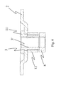
FIG. 6 shows a cross-sectional view, along the line III-III inFigure 3 , of the adjustable support according to the present invention with some parts removed so that other parts thereof may be seen more clearly. - With reference to the accompanying
drawings 1 denotes in its entirety the adjustable support according to the present invention. - It is conventionally intended to engage with the hinge of a leaf (not shown) of a gate, a main entrance door or the like so as to support it rotatably on the upright of a frame or on a masonry pillar which are fixed relative to the ground.
- Obviously the adjustable hinge support according to the present invention may be used to support leaves or movable parts of fixtures of any kind without thereby departing from the scope of protection of the present patent.
- With reference to the accompanying drawings, the
hinge support 1 comprises, in a manner conventional per se, asupport plate 2 intended to be fixed to the leaf support upright or pillar, and abush 3 which is internally threaded and projects perpendicularly from theplate 2 in the direction indicated by Z. - The
plate 2 has a flat, for example a polygonal, form and defines a visible outer surface 2' and aninner surface 2" intended to be fixed to the wall of the upright or the pillar. - Preferably, the
plate 2 is fixed to the pillar by means of fixing screws which can be inserted in through-holes 20 formed in the corners of theplate 2. - The
support 1 also comprises an eye-piece 4 which engages by means of screwing of its threadedshank 5 with the threaded inner surface 3' of thebush 3 and has an enlargedhead 6 with aseat 7, in particular consisting of a through-hole, for rotatably receiving the pin of a hinge fastened to the leaf and for allowing it to rotate about a vertical axis indicated by Y. - A
locking ring 8 is screwed onto theshank 5 of the eye-piece 4 and, coming into contact against thefree edge 9 of thebush 3, has the function of acting as a counter lock-nut for rigidly fixing the eye-piece 4 with respect to thebush 3, preventing the said eye-piece 4 from being freely unscrewed or screwed. - According to the idea forming the basis of the present invention the
support plate 2 is provided with a through-eyelet 10 and thebush 3 is inserted inside the through-eyelet 10 as far as an end-of-travel position defined by itshead 11 coming into contact against the rear surface 2' of the plate. Furthermore, thebush 3 has a threadedouter surface 3" on which an adjustingring 12 can be screwably engaged, said ring being able to be fixed at the desired height by means ofremovable retaining means 13. - Preferably, the removable retaining means 13 are formed by means of one or more grub screws which can be inserted inside transverse threaded through-holes formed in the adjusting
ring 12 and able to fix or free the latter with respect to thebush 3. - In greater detail, the
eyelet 10 extends along an axis X which is substantially horizontal when theplate 2 is fixed to the leaf support upright or pillar so as to allow right-hand or left-hand adjustment of the position of the hinge. - The
eyelet 10 is arranged centred in the bottom of a depression 18 formed by means of deep-drawing in the central portion of theplate 2, the depth of which has a height sufficient to seat thehead 11 of thebush 3, preferably consisting of a perimetrally projecting ring. - The present invention also relates to a method for adjusting the position of the
support 1 described above, which allows variation in the position of the hinge both along the horizontal axis X in order to perform a right-hand or left-hand adjustment and along the axis Z in order to vary the distance of the hinge from the support upright or pillar. - In order to perform the right-hand or left-hand adjustment the method envisages loosening the adjusting
ring 12 on theplate 2 and then performing positioning of thebush 3 inside theeyelet 10 in order to obtain the desired position thereof along the axis X. - Then, once the position of the
bush 3 has been defined, the adjustment envisages performing tightening the adjustingring 12 against theplate 2 so as to fasten thebush 3 to thesupport plate 2 itself. - At this point the adjusting
ring 12 and the bush are fastened together by means of a locking operation involving engagement of theretaining means 13, which requires in particular screwing of the grub screws inserted inside the threaded holes of the adjustingring 12 against the outer surface of thebush 3. - Adjustment of the axial position of the eye-
piece 4 along its axis Z is performed starting from the condition where the adjustingring 12 is slack on thesupport plate 2 and the tighteningring 8 is slack on thefree edge 9 of the bush. - At this point locking of the adjusting
ring 12 on thebush 3 is performed via theretaining means 13 and then axial adjustment of the eye-piece 4 is performed by means of a rotation of the adjustingring 12. - The latter has, integrally fixed to it, the
bush 3 and therefore causes, with its rotation, the eye-piece to be displaced axially inside thebush 3 by means of screwing or unscrewing in both senses of the direction Z. - Once the position of the eye-piece along the axis Z has been determined it will be possible to release the adjusting
ring 12 from thebush 3 by means of disengagement, from thebush 3, of thegrub screws 13 inserted in the threaded holes of thering 12. - Then it will be possible to perform tightening of the adjusting
ring 12 against theplate 2 so as to fix thebush 3 to thesupport plate 2 and then locking of the adjustingring 12 by means of engagement of thegrub screws 13 against theouter surface 3" of thebush 3. - The invention thus conceived therefore achieves the predefined objects.
- Obviously it may assume in its practical embodiment also forms and configurations different from that illustrated above without thereby departing from the present scope of protection.
- Moreover all the details may be replaced by technically equivalent elements and the dimensions, the forms and the materials used may be of any nature according to requirements.
Claims (7)
- Adjustable hinge support designed to allow rotation of a leaf, in particular a gate, comprising:- a support plate intended to be fixed to an upright or to a pillar for supporting said leaf;- at least one internally threaded bush which is mechanically associated with said plate and projects from it;- at least one eye-piece which has a threaded shank able to engage with the threading of said bush and a head having a seat able to receive the pin of a hinge fastened to the leaf;- at least one tightening ring engaged by means of screwing on the shank of said eye-piece and able to fix the latter on said bush, coming into contact against the free edge of said bush;characterized in that:- said plate has a through-eyelet;- said bush is inserted inside eyelet as far as an end-of-travel position defined by contact of its head against the rear surface of said plate and has a threaded outer surface on which an adjusting ring is screwably engaged, said ring being able to be fixed at the desired height by means of removable retaining means.
- Adjustable support according to Claim 1, characterized in that said removable retaining means are formed by means of one or more grub screws which can be inserted in transverse through-holes formed in said adjusting ring and able to act on said bush so as to fix or free said adjusting ring with respect to said bush.
- Adjustable support according to Claim 1, characterized in that the head of said bush consists of a projecting perimetral ring.
- Adjustable support according to Claim 1, characterized in that said plate has a depression inside which said eyelet is formed, said depression having a depth greater than or equal to the height of the head of said bush.
- Adjustable support according to Claim 1, characterized in that said eyelet has an extension mainly along a substantially horizontal X axis when said plate is fixed to the leaf support upright or pillar so as to allow right-hand or left-hand adjustment of the position of the hinge.
- Method for adjusting the position of said support according to Claim 1, characterized in that it comprises the following operating steps:- positioning the bush inside the eyelet with said adjusting ring loose on the plate;- tightening the adjusting ring against the plate so as to fix said bush to the support plate;- locking said adjusting ring by means of engagement of said retaining means against the outer surface of said bush.
- Method for adjusting the position of said support according to Claim 1, characterized in that it comprises the following operating steps:- locking said adjusting ring with said bush by means of said retaining means with said adjusting ring slack on the support plate and said tightening ring loose on the free edge of said bush;- rotating said adjusting ring on which said bush is integrally fixed so as to displace axially said eye-piece inside said bush;- releasing said ring from said bush by means of disengagement of said retaining means from said bush;- tightening the adjusting ring against the plate so as to fix said bush to the support plate;- locking said adjusting ring by means of engagement of said retaining means against the outer surface of said bush.
Applications Claiming Priority (1)
| Application Number | Priority Date | Filing Date | Title |
|---|---|---|---|
| ITPD20070221 ITPD20070221A1 (en) | 2007-06-28 | 2007-06-28 | ADJUSTABLE CARDINO SUPPORT AND ADJUSTMENT METHOD OF THE SUPPORT POSITION |
Publications (2)
| Publication Number | Publication Date |
|---|---|
| EP2009207A2 true EP2009207A2 (en) | 2008-12-31 |
| EP2009207A3 EP2009207A3 (en) | 2011-03-09 |
Family
ID=39764868
Family Applications (1)
| Application Number | Title | Priority Date | Filing Date |
|---|---|---|---|
| EP08158210A Withdrawn EP2009207A3 (en) | 2007-06-28 | 2008-06-13 | Adjustable hinge support and method for adjusting the position of said support |
Country Status (2)
| Country | Link |
|---|---|
| EP (1) | EP2009207A3 (en) |
| IT (1) | ITPD20070221A1 (en) |
Cited By (2)
| Publication number | Priority date | Publication date | Assignee | Title |
|---|---|---|---|---|
| WO2015051830A1 (en) * | 2013-10-08 | 2015-04-16 | Purus Ab | Supporting device for sink |
| CN112943019A (en) * | 2019-12-11 | 2021-06-11 | 多玛凯拔德国有限公司 | Device for moving a door leaf |
Family Cites Families (2)
| Publication number | Priority date | Publication date | Assignee | Title |
|---|---|---|---|---|
| DE3217131A1 (en) * | 1982-05-07 | 1983-11-10 | Eckhard 4500 Osnabrück Pörschke | Adjustable shutter hinges |
| FR2679590B1 (en) * | 1991-07-26 | 1995-10-06 | Tordo Belgrano Sa | ADJUSTABLE SEALING HINGE. |
-
2007
- 2007-06-28 IT ITPD20070221 patent/ITPD20070221A1/en unknown
-
2008
- 2008-06-13 EP EP08158210A patent/EP2009207A3/en not_active Withdrawn
Cited By (2)
| Publication number | Priority date | Publication date | Assignee | Title |
|---|---|---|---|---|
| WO2015051830A1 (en) * | 2013-10-08 | 2015-04-16 | Purus Ab | Supporting device for sink |
| CN112943019A (en) * | 2019-12-11 | 2021-06-11 | 多玛凯拔德国有限公司 | Device for moving a door leaf |
Also Published As
| Publication number | Publication date |
|---|---|
| EP2009207A3 (en) | 2011-03-09 |
| ITPD20070221A1 (en) | 2008-12-29 |
Similar Documents
| Publication | Publication Date | Title |
|---|---|---|
| US5806144A (en) | Device for a door hinge structure | |
| DE69623743T2 (en) | Bent handle and device for attaching it | |
| AU2010215084A1 (en) | An adjustable hinge | |
| US20160312509A1 (en) | Door closer assembly | |
| EP1267691B1 (en) | Shower partition | |
| EP2009207A2 (en) | Adjustable hinge support and method for adjusting the position of said support | |
| EP1810806A2 (en) | Side system for a casting mold and an attaching unit | |
| US11828102B2 (en) | Adjustable packer apparatus | |
| SE434864B (en) | hinges | |
| DE69406117T2 (en) | FLOOR DOOR CLOSER | |
| KR20090106066A (en) | Fixture for Window Installation | |
| US7594357B2 (en) | Manual lift gate system | |
| US12398587B1 (en) | Window hinge assembly and methods | |
| EP1598510A2 (en) | An adjustable door hinge | |
| KR101175649B1 (en) | Rotation support apparatus for door | |
| CN105332580B (en) | A kind of arrangement for adjusting height of hinge frame page | |
| US12385302B2 (en) | Gate hinge | |
| DK178170B1 (en) | Hinged cover | |
| KR20200000535U (en) | door hinge | |
| KR200337125Y1 (en) | pillow of tempered glass door | |
| KR200388213Y1 (en) | Adjustment Apparatus for Setting-Position of Floor-Hinge | |
| CS231151B2 (en) | Deer casing | |
| US20140173987A1 (en) | Classic Step Store Gate | |
| KR900008947Y1 (en) | Pivot in steel door | |
| JP5240779B2 (en) | Flip-up gate |
Legal Events
| Date | Code | Title | Description |
|---|---|---|---|
| PUAI | Public reference made under article 153(3) epc to a published international application that has entered the european phase |
Free format text: ORIGINAL CODE: 0009012 |
|
| AK | Designated contracting states |
Kind code of ref document: A2 Designated state(s): AT BE BG CH CY CZ DE DK EE ES FI FR GB GR HR HU IE IS IT LI LT LU LV MC MT NL NO PL PT RO SE SI SK TR |
|
| AX | Request for extension of the european patent |
Extension state: AL BA MK RS |
|
| PUAL | Search report despatched |
Free format text: ORIGINAL CODE: 0009013 |
|
| AK | Designated contracting states |
Kind code of ref document: A3 Designated state(s): AT BE BG CH CY CZ DE DK EE ES FI FR GB GR HR HU IE IS IT LI LT LU LV MC MT NL NO PL PT RO SE SI SK TR |
|
| AX | Request for extension of the european patent |
Extension state: AL BA MK RS |
|
| AKY | No designation fees paid | ||
| REG | Reference to a national code |
Ref country code: DE Ref legal event code: R108 |
|
| REG | Reference to a national code |
Ref country code: DE Ref legal event code: R108 Effective date: 20111116 |
|
| STAA | Information on the status of an ep patent application or granted ep patent |
Free format text: STATUS: THE APPLICATION IS DEEMED TO BE WITHDRAWN |
|
| 18D | Application deemed to be withdrawn |
Effective date: 20110913 |