EP2009207A2 - Support de charnière réglable et procédé d'ajustement de la position de ce support - Google Patents
Support de charnière réglable et procédé d'ajustement de la position de ce support Download PDFInfo
- Publication number
- EP2009207A2 EP2009207A2 EP08158210A EP08158210A EP2009207A2 EP 2009207 A2 EP2009207 A2 EP 2009207A2 EP 08158210 A EP08158210 A EP 08158210A EP 08158210 A EP08158210 A EP 08158210A EP 2009207 A2 EP2009207 A2 EP 2009207A2
- Authority
- EP
- European Patent Office
- Prior art keywords
- bush
- plate
- ring
- adjusting ring
- support
- Prior art date
- Legal status (The legal status is an assumption and is not a legal conclusion. Google has not performed a legal analysis and makes no representation as to the accuracy of the status listed.)
- Withdrawn
Links
Images


Classifications
-
- E—FIXED CONSTRUCTIONS
- E05—LOCKS; KEYS; WINDOW OR DOOR FITTINGS; SAFES
- E05D—HINGES OR SUSPENSION DEVICES FOR DOORS, WINDOWS OR WINGS
- E05D7/00—Hinges or pivots of special construction
- E05D7/04—Hinges adjustable relative to the wing or the frame
-
- E—FIXED CONSTRUCTIONS
- E05—LOCKS; KEYS; WINDOW OR DOOR FITTINGS; SAFES
- E05D—HINGES OR SUSPENSION DEVICES FOR DOORS, WINDOWS OR WINGS
- E05D5/00—Construction of single parts, e.g. the parts for attachment
- E05D5/02—Parts for attachment, e.g. flaps
-
- E—FIXED CONSTRUCTIONS
- E05—LOCKS; KEYS; WINDOW OR DOOR FITTINGS; SAFES
- E05D—HINGES OR SUSPENSION DEVICES FOR DOORS, WINDOWS OR WINGS
- E05D7/00—Hinges or pivots of special construction
- E05D7/04—Hinges adjustable relative to the wing or the frame
- E05D7/043—Hinges adjustable relative to the wing or the frame by means of dowel attachments
-
- E—FIXED CONSTRUCTIONS
- E05—LOCKS; KEYS; WINDOW OR DOOR FITTINGS; SAFES
- E05D—HINGES OR SUSPENSION DEVICES FOR DOORS, WINDOWS OR WINGS
- E05D7/00—Hinges or pivots of special construction
- E05D7/04—Hinges adjustable relative to the wing or the frame
- E05D7/043—Hinges adjustable relative to the wing or the frame by means of dowel attachments
- E05D2007/0446—Hinges adjustable relative to the wing or the frame by means of dowel attachments with threaded bolts fixedly mounted on the hinge part
-
- E—FIXED CONSTRUCTIONS
- E05—LOCKS; KEYS; WINDOW OR DOOR FITTINGS; SAFES
- E05Y—INDEXING SCHEME ASSOCIATED WITH SUBCLASSES E05D AND E05F, RELATING TO CONSTRUCTION ELEMENTS, ELECTRIC CONTROL, POWER SUPPLY, POWER SIGNAL OR TRANSMISSION, USER INTERFACES, MOUNTING OR COUPLING, DETAILS, ACCESSORIES, AUXILIARY OPERATIONS NOT OTHERWISE PROVIDED FOR, APPLICATION THEREOF
- E05Y2600/00—Mounting or coupling arrangements for elements provided for in this subclass
- E05Y2600/60—Mounting or coupling members; Accessories therefor
- E05Y2600/61—Threaded members
-
- E—FIXED CONSTRUCTIONS
- E05—LOCKS; KEYS; WINDOW OR DOOR FITTINGS; SAFES
- E05Y—INDEXING SCHEME ASSOCIATED WITH SUBCLASSES E05D AND E05F, RELATING TO CONSTRUCTION ELEMENTS, ELECTRIC CONTROL, POWER SUPPLY, POWER SIGNAL OR TRANSMISSION, USER INTERFACES, MOUNTING OR COUPLING, DETAILS, ACCESSORIES, AUXILIARY OPERATIONS NOT OTHERWISE PROVIDED FOR, APPLICATION THEREOF
- E05Y2600/00—Mounting or coupling arrangements for elements provided for in this subclass
- E05Y2600/60—Mounting or coupling members; Accessories therefor
- E05Y2600/62—Bolts
-
- E—FIXED CONSTRUCTIONS
- E05—LOCKS; KEYS; WINDOW OR DOOR FITTINGS; SAFES
- E05Y—INDEXING SCHEME ASSOCIATED WITH SUBCLASSES E05D AND E05F, RELATING TO CONSTRUCTION ELEMENTS, ELECTRIC CONTROL, POWER SUPPLY, POWER SIGNAL OR TRANSMISSION, USER INTERFACES, MOUNTING OR COUPLING, DETAILS, ACCESSORIES, AUXILIARY OPERATIONS NOT OTHERWISE PROVIDED FOR, APPLICATION THEREOF
- E05Y2600/00—Mounting or coupling arrangements for elements provided for in this subclass
- E05Y2600/60—Mounting or coupling members; Accessories therefor
- E05Y2600/626—Plates or brackets
-
- E—FIXED CONSTRUCTIONS
- E05—LOCKS; KEYS; WINDOW OR DOOR FITTINGS; SAFES
- E05Y—INDEXING SCHEME ASSOCIATED WITH SUBCLASSES E05D AND E05F, RELATING TO CONSTRUCTION ELEMENTS, ELECTRIC CONTROL, POWER SUPPLY, POWER SIGNAL OR TRANSMISSION, USER INTERFACES, MOUNTING OR COUPLING, DETAILS, ACCESSORIES, AUXILIARY OPERATIONS NOT OTHERWISE PROVIDED FOR, APPLICATION THEREOF
- E05Y2800/00—Details, accessories and auxiliary operations not otherwise provided for
- E05Y2800/20—Combinations of elements
- E05Y2800/205—Combinations of elements forming a unit
-
- E—FIXED CONSTRUCTIONS
- E05—LOCKS; KEYS; WINDOW OR DOOR FITTINGS; SAFES
- E05Y—INDEXING SCHEME ASSOCIATED WITH SUBCLASSES E05D AND E05F, RELATING TO CONSTRUCTION ELEMENTS, ELECTRIC CONTROL, POWER SUPPLY, POWER SIGNAL OR TRANSMISSION, USER INTERFACES, MOUNTING OR COUPLING, DETAILS, ACCESSORIES, AUXILIARY OPERATIONS NOT OTHERWISE PROVIDED FOR, APPLICATION THEREOF
- E05Y2800/00—Details, accessories and auxiliary operations not otherwise provided for
- E05Y2800/26—Form or shape
- E05Y2800/29—Form or shape forming a unitary piece with another element
-
- E—FIXED CONSTRUCTIONS
- E05—LOCKS; KEYS; WINDOW OR DOOR FITTINGS; SAFES
- E05Y—INDEXING SCHEME ASSOCIATED WITH SUBCLASSES E05D AND E05F, RELATING TO CONSTRUCTION ELEMENTS, ELECTRIC CONTROL, POWER SUPPLY, POWER SIGNAL OR TRANSMISSION, USER INTERFACES, MOUNTING OR COUPLING, DETAILS, ACCESSORIES, AUXILIARY OPERATIONS NOT OTHERWISE PROVIDED FOR, APPLICATION THEREOF
- E05Y2800/00—Details, accessories and auxiliary operations not otherwise provided for
- E05Y2800/26—Form or shape
- E05Y2800/292—Form or shape having apertures
- E05Y2800/296—Slots
-
- E—FIXED CONSTRUCTIONS
- E05—LOCKS; KEYS; WINDOW OR DOOR FITTINGS; SAFES
- E05Y—INDEXING SCHEME ASSOCIATED WITH SUBCLASSES E05D AND E05F, RELATING TO CONSTRUCTION ELEMENTS, ELECTRIC CONTROL, POWER SUPPLY, POWER SIGNAL OR TRANSMISSION, USER INTERFACES, MOUNTING OR COUPLING, DETAILS, ACCESSORIES, AUXILIARY OPERATIONS NOT OTHERWISE PROVIDED FOR, APPLICATION THEREOF
- E05Y2900/00—Application of doors, windows, wings or fittings thereof
- E05Y2900/40—Application of doors, windows, wings or fittings thereof for gates
Definitions
- the present invention concerns an adjustable hinge support and a method for adjusting the position of said support.
- the support in question is intended to be used advantageously for supporting rotatably leaves of fixtures of all kinds and in particular gates or main entrance doors between an open position and a closed position.
- the support may be arranged at different heights on the upright or pillar intended to support the leaf of the fixture or gate.
- adjustable hinge supports are available commercially, these being traditionally associated with a metal support bracket fastened to the fixed - for example masonry - pillar so as to support a gate.
- this bracket is fitted with a bearing inside which the hinge of the gate leaf is pivotably mounted so as to allow the latter to perform a rotational closing and opening movement about a generally vertical axis.
- the bearing is advantageously connected to the bracket by means of adjustable fixing means which allow a variation in the position of the hinge with respect to the bracket during mounting of the gate in order to allow control over the height of the said gate.
- hinge supports of the known type comprise an internally threaded bush rigidly fastened to a plate to be fixed to the pillar of the gate.
- the threaded shank of the eye-piece of the leaf support hinge engages inside this bush.
- a nut/lock-nut mechanism it is possible to fix at different depths the shank of the eye-piece inside the bush, allowing adjustment of the position of the leaf support hinge.
- the operator when making holes in the pillar in order to fix the support plate, comes up against stones or steel rods in the case of reinforced concrete pillars. These circumstances mean that the operator must fix the support plate so that it is slightly displaced laterally with respect to the desired position.
- the main object of the present invention is therefore to eliminate the drawbacks of the art known hitherto by providing an adjustable hinge support which allows easy and complete adjustment of the hinge position.
- Another object of the present invention is to provide a support resulting in limited costs for installation of the leaves of a gate or the like.
- a further object of the present invention is to provide a support which is constructionally simple, low-cost and operationally entirely reliable.
- Another object of the present invention is to provide a method for adjusting the hinge support which is particularly easy to implement and is able to vary precisely the position of the hinge.
- adjustable hinge support may be used to support leaves or movable parts of fixtures of any kind without thereby departing from the scope of protection of the present patent.
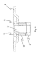
- the hinge support 1 comprises, in a manner conventional per se, a support plate 2 intended to be fixed to the leaf support upright or pillar, and a bush 3 which is internally threaded and projects perpendicularly from the plate 2 in the direction indicated by Z.
- the plate 2 has a flat, for example a polygonal, form and defines a visible outer surface 2' and an inner surface 2" intended to be fixed to the wall of the upright or the pillar.
- the plate 2 is fixed to the pillar by means of fixing screws which can be inserted in through-holes 20 formed in the corners of the plate 2.
- the support 1 also comprises an eye-piece 4 which engages by means of screwing of its threaded shank 5 with the threaded inner surface 3' of the bush 3 and has an enlarged head 6 with a seat 7, in particular consisting of a through-hole, for rotatably receiving the pin of a hinge fastened to the leaf and for allowing it to rotate about a vertical axis indicated by Y.
- a locking ring 8 is screwed onto the shank 5 of the eye-piece 4 and, coming into contact against the free edge 9 of the bush 3, has the function of acting as a counter lock-nut for rigidly fixing the eye-piece 4 with respect to the bush 3, preventing the said eye-piece 4 from being freely unscrewed or screwed.
- the support plate 2 is provided with a through-eyelet 10 and the bush 3 is inserted inside the through-eyelet 10 as far as an end-of-travel position defined by its head 11 coming into contact against the rear surface 2' of the plate.
- the bush 3 has a threaded outer surface 3" on which an adjusting ring 12 can be screwably engaged, said ring being able to be fixed at the desired height by means of removable retaining means 13.
- the removable retaining means 13 are formed by means of one or more grub screws which can be inserted inside transverse threaded through-holes formed in the adjusting ring 12 and able to fix or free the latter with respect to the bush 3.
- the eyelet 10 extends along an axis X which is substantially horizontal when the plate 2 is fixed to the leaf support upright or pillar so as to allow right-hand or left-hand adjustment of the position of the hinge.
- the eyelet 10 is arranged centred in the bottom of a depression 18 formed by means of deep-drawing in the central portion of the plate 2, the depth of which has a height sufficient to seat the head 11 of the bush 3, preferably consisting of a perimetrally projecting ring.
- the present invention also relates to a method for adjusting the position of the support 1 described above, which allows variation in the position of the hinge both along the horizontal axis X in order to perform a right-hand or left-hand adjustment and along the axis Z in order to vary the distance of the hinge from the support upright or pillar.
- the method envisages loosening the adjusting ring 12 on the plate 2 and then performing positioning of the bush 3 inside the eyelet 10 in order to obtain the desired position thereof along the axis X.
- the adjustment envisages performing tightening the adjusting ring 12 against the plate 2 so as to fasten the bush 3 to the support plate 2 itself.
- Adjustment of the axial position of the eye-piece 4 along its axis Z is performed starting from the condition where the adjusting ring 12 is slack on the support plate 2 and the tightening ring 8 is slack on the free edge 9 of the bush.
- the latter has, integrally fixed to it, the bush 3 and therefore causes, with its rotation, the eye-piece to be displaced axially inside the bush 3 by means of screwing or unscrewing in both senses of the direction Z.
- the invention thus conceived therefore achieves the predefined objects.
Landscapes
- Engineering & Computer Science (AREA)
- Mechanical Engineering (AREA)
- Hinges (AREA)
- Medicines Containing Plant Substances (AREA)
- Die Bonding (AREA)
- Vehicle Body Suspensions (AREA)
Applications Claiming Priority (1)
| Application Number | Priority Date | Filing Date | Title |
|---|---|---|---|
| ITPD20070221 ITPD20070221A1 (it) | 2007-06-28 | 2007-06-28 | Supporto regolabile per cardini e metodo di regolazione della posizione di detto supporto |
Publications (2)
| Publication Number | Publication Date |
|---|---|
| EP2009207A2 true EP2009207A2 (fr) | 2008-12-31 |
| EP2009207A3 EP2009207A3 (fr) | 2011-03-09 |
Family
ID=39764868
Family Applications (1)
| Application Number | Title | Priority Date | Filing Date |
|---|---|---|---|
| EP08158210A Withdrawn EP2009207A3 (fr) | 2007-06-28 | 2008-06-13 | Support de charnière réglable et procédé d'ajustement de la position de ce support |
Country Status (2)
| Country | Link |
|---|---|
| EP (1) | EP2009207A3 (fr) |
| IT (1) | ITPD20070221A1 (fr) |
Cited By (2)
| Publication number | Priority date | Publication date | Assignee | Title |
|---|---|---|---|---|
| WO2015051830A1 (fr) * | 2013-10-08 | 2015-04-16 | Purus Ab | Dispositif de support pour évier |
| CN112943019A (zh) * | 2019-12-11 | 2021-06-11 | 多玛凯拔德国有限公司 | 用于移动门扇的设备 |
Family Cites Families (2)
| Publication number | Priority date | Publication date | Assignee | Title |
|---|---|---|---|---|
| DE3217131A1 (de) * | 1982-05-07 | 1983-11-10 | Eckhard 4500 Osnabrück Pörschke | Verstellbare ladenbaender |
| FR2679590B1 (fr) * | 1991-07-26 | 1995-10-06 | Tordo Belgrano Sa | Gond a sceller reglable. |
-
2007
- 2007-06-28 IT ITPD20070221 patent/ITPD20070221A1/it unknown
-
2008
- 2008-06-13 EP EP08158210A patent/EP2009207A3/fr not_active Withdrawn
Cited By (2)
| Publication number | Priority date | Publication date | Assignee | Title |
|---|---|---|---|---|
| WO2015051830A1 (fr) * | 2013-10-08 | 2015-04-16 | Purus Ab | Dispositif de support pour évier |
| CN112943019A (zh) * | 2019-12-11 | 2021-06-11 | 多玛凯拔德国有限公司 | 用于移动门扇的设备 |
Also Published As
| Publication number | Publication date |
|---|---|
| EP2009207A3 (fr) | 2011-03-09 |
| ITPD20070221A1 (it) | 2008-12-29 |
Similar Documents
| Publication | Publication Date | Title |
|---|---|---|
| US5806144A (en) | Device for a door hinge structure | |
| DE69623743T2 (de) | Gebogener Handgriff sowie Vorrichtung zu deren Anbringung | |
| AU2010215084A1 (en) | An adjustable hinge | |
| US20160312509A1 (en) | Door closer assembly | |
| EP1267691B1 (fr) | Separation de douche | |
| EP2009207A2 (fr) | Support de charnière réglable et procédé d'ajustement de la position de ce support | |
| EP1810806A2 (fr) | Dispositif de paroi latérale pour moule de coulage et unité d'attache | |
| US11828102B2 (en) | Adjustable packer apparatus | |
| SE434864B (sv) | Gangjern | |
| DE69406117T2 (de) | Bodentürschliesser | |
| KR20090106066A (ko) | 창호 설치용 고정구 | |
| US7594357B2 (en) | Manual lift gate system | |
| US12398587B1 (en) | Window hinge assembly and methods | |
| EP1598510A2 (fr) | Une charnière de porte réglable | |
| KR101175649B1 (ko) | 도어의 회전지지장치 | |
| CN105332580B (zh) | 一种铰链框页的高度调节装置 | |
| US12385302B2 (en) | Gate hinge | |
| DK178170B1 (da) | Hængslet dæksel | |
| KR20200000535U (ko) | 대문용 상부 힌지 | |
| KR200337125Y1 (ko) | 강화유리도어의 축받이 | |
| KR200388213Y1 (ko) | 플로어힌지의 위치조절장치 | |
| CS231151B2 (en) | Deer casing | |
| US20140173987A1 (en) | Classic Step Store Gate | |
| KR900008947Y1 (ko) | 철문용 피벗힌지(Pivot Hinge) | |
| JP5240779B2 (ja) | 跳ね上げ式門扉 |
Legal Events
| Date | Code | Title | Description |
|---|---|---|---|
| PUAI | Public reference made under article 153(3) epc to a published international application that has entered the european phase |
Free format text: ORIGINAL CODE: 0009012 |
|
| AK | Designated contracting states |
Kind code of ref document: A2 Designated state(s): AT BE BG CH CY CZ DE DK EE ES FI FR GB GR HR HU IE IS IT LI LT LU LV MC MT NL NO PL PT RO SE SI SK TR |
|
| AX | Request for extension of the european patent |
Extension state: AL BA MK RS |
|
| PUAL | Search report despatched |
Free format text: ORIGINAL CODE: 0009013 |
|
| AK | Designated contracting states |
Kind code of ref document: A3 Designated state(s): AT BE BG CH CY CZ DE DK EE ES FI FR GB GR HR HU IE IS IT LI LT LU LV MC MT NL NO PL PT RO SE SI SK TR |
|
| AX | Request for extension of the european patent |
Extension state: AL BA MK RS |
|
| AKY | No designation fees paid | ||
| REG | Reference to a national code |
Ref country code: DE Ref legal event code: R108 |
|
| REG | Reference to a national code |
Ref country code: DE Ref legal event code: R108 Effective date: 20111116 |
|
| STAA | Information on the status of an ep patent application or granted ep patent |
Free format text: STATUS: THE APPLICATION IS DEEMED TO BE WITHDRAWN |
|
| 18D | Application deemed to be withdrawn |
Effective date: 20110913 |