EP2009253A1 - Procédé de décomposition d'un hydrate de gaz et appareil prévu à cet effet dans un système générateur d'électricité combiné à une turbine à gaz - Google Patents
Procédé de décomposition d'un hydrate de gaz et appareil prévu à cet effet dans un système générateur d'électricité combiné à une turbine à gaz Download PDFInfo
- Publication number
- EP2009253A1 EP2009253A1 EP06731913A EP06731913A EP2009253A1 EP 2009253 A1 EP2009253 A1 EP 2009253A1 EP 06731913 A EP06731913 A EP 06731913A EP 06731913 A EP06731913 A EP 06731913A EP 2009253 A1 EP2009253 A1 EP 2009253A1
- Authority
- EP
- European Patent Office
- Prior art keywords
- gas
- gas hydrate
- condenser
- condensate
- power generation
- Prior art date
- Legal status (The legal status is an assumption and is not a legal conclusion. Google has not performed a legal analysis and makes no representation as to the accuracy of the status listed.)
- Withdrawn
Links
Images


Classifications
-
- F—MECHANICAL ENGINEERING; LIGHTING; HEATING; WEAPONS; BLASTING
- F01—MACHINES OR ENGINES IN GENERAL; ENGINE PLANTS IN GENERAL; STEAM ENGINES
- F01K—STEAM ENGINE PLANTS; STEAM ACCUMULATORS; ENGINE PLANTS NOT OTHERWISE PROVIDED FOR; ENGINES USING SPECIAL WORKING FLUIDS OR CYCLES
- F01K23/00—Plants characterised by more than one engine delivering power external to the plant, the engines being driven by different fluids
- F01K23/02—Plants characterised by more than one engine delivering power external to the plant, the engines being driven by different fluids the engine cycles being thermally coupled
- F01K23/06—Plants characterised by more than one engine delivering power external to the plant, the engines being driven by different fluids the engine cycles being thermally coupled combustion heat from one cycle heating the fluid in another cycle
- F01K23/10—Plants characterised by more than one engine delivering power external to the plant, the engines being driven by different fluids the engine cycles being thermally coupled combustion heat from one cycle heating the fluid in another cycle with exhaust fluid of one cycle heating the fluid in another cycle
-
- F—MECHANICAL ENGINEERING; LIGHTING; HEATING; WEAPONS; BLASTING
- F01—MACHINES OR ENGINES IN GENERAL; ENGINE PLANTS IN GENERAL; STEAM ENGINES
- F01K—STEAM ENGINE PLANTS; STEAM ACCUMULATORS; ENGINE PLANTS NOT OTHERWISE PROVIDED FOR; ENGINES USING SPECIAL WORKING FLUIDS OR CYCLES
- F01K9/00—Plants characterised by condensers arranged or modified to co-operate with the engines
- F01K9/003—Plants characterised by condensers arranged or modified to co-operate with the engines condenser cooling circuits
-
- F—MECHANICAL ENGINEERING; LIGHTING; HEATING; WEAPONS; BLASTING
- F02—COMBUSTION ENGINES; HOT-GAS OR COMBUSTION-PRODUCT ENGINE PLANTS
- F02C—GAS-TURBINE PLANTS; AIR INTAKES FOR JET-PROPULSION PLANTS; CONTROLLING FUEL SUPPLY IN AIR-BREATHING JET-PROPULSION PLANTS
- F02C3/00—Gas-turbine plants characterised by the use of combustion products as the working fluid
- F02C3/20—Gas-turbine plants characterised by the use of combustion products as the working fluid using a special fuel, oxidant, or dilution fluid to generate the combustion products
- F02C3/26—Gas-turbine plants characterised by the use of combustion products as the working fluid using a special fuel, oxidant, or dilution fluid to generate the combustion products the fuel or oxidant being solid or pulverulent, e.g. in slurry or suspension
- F02C3/28—Gas-turbine plants characterised by the use of combustion products as the working fluid using a special fuel, oxidant, or dilution fluid to generate the combustion products the fuel or oxidant being solid or pulverulent, e.g. in slurry or suspension using a separate gas producer for gasifying the fuel before combustion
-
- F—MECHANICAL ENGINEERING; LIGHTING; HEATING; WEAPONS; BLASTING
- F28—HEAT EXCHANGE IN GENERAL
- F28B—STEAM OR VAPOUR CONDENSERS
- F28B5/00—Condensers employing a combination of the methods covered by main groups F28B1/00 and F28B3/00; Other condensers
-
- F—MECHANICAL ENGINEERING; LIGHTING; HEATING; WEAPONS; BLASTING
- F28—HEAT EXCHANGE IN GENERAL
- F28D—HEAT-EXCHANGE APPARATUS, NOT PROVIDED FOR IN ANOTHER SUBCLASS, IN WHICH THE HEAT-EXCHANGE MEDIA DO NOT COME INTO DIRECT CONTACT
- F28D7/00—Heat-exchange apparatus having stationary tubular conduit assemblies for both heat-exchange media, the media being in contact with different sides of a conduit wall
- F28D7/16—Heat-exchange apparatus having stationary tubular conduit assemblies for both heat-exchange media, the media being in contact with different sides of a conduit wall the conduits being arranged in parallel spaced relation
-
- Y—GENERAL TAGGING OF NEW TECHNOLOGICAL DEVELOPMENTS; GENERAL TAGGING OF CROSS-SECTIONAL TECHNOLOGIES SPANNING OVER SEVERAL SECTIONS OF THE IPC; TECHNICAL SUBJECTS COVERED BY FORMER USPC CROSS-REFERENCE ART COLLECTIONS [XRACs] AND DIGESTS
- Y02—TECHNOLOGIES OR APPLICATIONS FOR MITIGATION OR ADAPTATION AGAINST CLIMATE CHANGE
- Y02E—REDUCTION OF GREENHOUSE GAS [GHG] EMISSIONS, RELATED TO ENERGY GENERATION, TRANSMISSION OR DISTRIBUTION
- Y02E20/00—Combustion technologies with mitigation potential
- Y02E20/16—Combined cycle power plant [CCPP], or combined cycle gas turbine [CCGT]
Definitions
- the present invention relates to a method of thermally decomposing gas hydrate, and an apparatus therefor, in a gas turbine combined power generation system.
- NGH natural gas hydrate
- LNG liquid natural gas
- NGH When regasifying NGH into natural gas, it has been proposed that NGH, being offloaded from an NGH carrier vessel and into an NGH facility, be fed into a gasification tank and then regasified using seawater. Seawater is also used as a heat source when gasifying LNG.
- NGH is a hydrate of natural gas and water, and the temperature difference between the temperature of NGH (-20 °C, for example) and the temperature of seawater (21 °C, for example) is small.
- NGH gasification is difficult compared to that of LNG.
- the heat transfer area during gasification must be inevitably made larger.
- the temperature (33 °C, for example) of the condenser in gas turbine combined power generation equipment is higher than the temperature of the seawater (typically, the seawater temperature is set to 21 °C). For this reason, by using steam condensate instead of seawater, a heat exchanger for gasification can be rendered unnecessary.
- the present invention was devised to resolve such problems, an object thereof being to provide a method and apparatus for thermally decomposing gas hydrate in a gas turbine combined power generation system, wherein a heat exchanger for gasification is rendered unnecessary, and wherein the condensate temperature does not fluctuate.
- the invention disclosed in claim 1 is a method of decomposing gas hydrate in a gas turbine combined power generation system, the gas turbine combined power generation system using, as a fuel, gas generated by decomposition of gas hydrate.
- the method includes the steps of: circulating condensate generated in a condenser to the vapor inlet side of the condenser; exchanging heat between the circulating condensate and circulating water supplied to decompose gas hydrate; and using the heat-exchanged circulating water to decompose gas hydrate.
- the invention disclosed in claim 2 is an apparatus for decomposing gas hydrate in a gas turbine combined power generation system, the gas turbine combined power generation system using, as a fuel, gas generated by decomposition of gas hydrate.
- the apparatus is provided with: a pump that circulates condensate generated in a condenser to the vapor inlet side of the condenser; a heat exchanger that causes heat to be exchanged between the circulating condensate and circulating water supplied to decompose gas hydrate; and a pump that circulates the circulating water to a gas hydrate thermal decomposition tank.
- the invention disclosed in claim 1 is utilized in a gas turbine combined power generation system using, as a fuel, gas generated by decomposition of gas hydrate.
- Condensate generated in a condenser is circulated to the vapor inlet side of the condenser, the circulating condensate is then made to exchange heat with circulating water supplied to decompose gas hydrate, and then the heat-exchanged circulating water is used to decompose gas hydrate. Consequently, the following advantages are obtained.
- the invention disclosed in claim 2 is utilized in a gas turbine combined power generation system using, as a fuel, gas generated by decomposition of gas hydrate, and is provided with: a pump that circulates condensate generated in a condenser to the vapor inlet side of the condenser; a heat exchanger that causes heat to be exchanged between the circulating condensate and circulating water supplied to decompose gas hydrate; and a pump that circulates the circulating water to a gas hydrate thermal decomposition tank.
- a pump that circulates condensate generated in a condenser to the vapor inlet side of the condenser
- a heat exchanger that causes heat to be exchanged between the circulating condensate and circulating water supplied to decompose gas hydrate
- a pump that circulates the circulating water to a gas hydrate thermal decomposition tank.
- the gas hydrate thermal decomposition reaction time is determined according to the temperature difference ( ⁇ T) between the equilibrium temperature of the gas hydrate in the gasification tank and the operating temperature in the tank. Since the present invention is able to increase ⁇ T, the gas hydrate thermal decomposition time can be shortened.
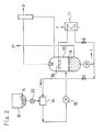
- FIG. 1 (A) represents gas turbine power generation equipment, and (B) represents a gas hydrate thermal decomposition apparatus.
- the gas turbine power generation equipment (A) includes a compressor 1 and a turbine 2 coaxially coupled about a turbine shaft 3, and burns fuel gas (more specifically, natural gas (b)) inside a combustion chamber 4 using air (a) compressed at the compressor 1. At that point, the high-temperature, high-pressure fuel gas (c) thus generated is expanded in the turbine 2 so as to drive a power generator 5 coupled to the turbine shaft 3.
- the gas turbine power generation equipment (A) feeds high-temperature exhaust gas (d) exhausted from the turbine 2 to a waste heat boiler 6, and steam (e) generated by heat recovery is then respectively expanded in steam turbines 7, 8, and 9 coupled to the turbine shaft 3, thereby driving the power generator 5.
- Steam (f) exhausted from the steam turbines 7, 8, and 9 is condensed at a condenser 10, the condensate being again returned to the waste heat boiler 6.
- the gas hydrate thermal decomposition apparatus (B) thermally decomposes gas hydrate (h) in pellet form in a gasification tank 32, the gas hydrate (h) having been transported to a storage tank 31 by a carrier vessel 30.
- the natural gas (b) generated by thermal decomposition is supplied to the above combustion chamber 4, while the dissociated liquid (m) generated at the same time is used as cooling water for intake cooling of the compressor 1, as boiler supply water for the waste heat boiler 6, and as ballast water for the carrier vessel 30.
- the gas hydrate (h) in the storage tank 31 is first finely crushed by a crusher (not shown in the drawings), and subsequently supplied to a mixer 34 by a rotary valve 33.
- the gas hydrate (h) (approx. 10 mm) inside the mixer 34 is slurried by circulating water (i) supplied from the gasification tank 32, and then fed into the gasification tank 32 by a slurry pump 35.
- the circulating water (i) from the gasification tank 32 is heated at a heat exchanger 11 using condensate (n) from the condenser 10 as a heat source, whereby the circulating water (i) is provided with the necessary decomposition heat for decomposing the gas hydrate (h).
- the gas hydrate (h) in the gasification tank 32 is sprayed with the heated circulating water (i) from spray nozzles 36 provided inside the tank.
- the gas hydrate (h) dissociates by thermal decomposition into natural gas (b) and a portion of the circulating water (i) (i.e., dissociated liquid).
- the natural gas (b) dissociated is fed into the gas turbine combustion chamber 4. Since the generated portion of the circulating water (i) (i.e., the dissociated liquid (m)) collects in the gasification tank 32, the dissociated liquid (m) is continually flushed.
- this portion of the circulating water (i) is used as cooling water for intake cooling of the gas turbine 2, as boiler supply water for the waste heat boiler 6, and as ballast water for the carrier vessel 30.
- all water except the boiler feed water for the waste heat boiler 6 is accumulated in a water tank 12, and subsequently added to the ballast water of the carrier vessel 30 by a recovered water transfer pump 13.
- the condensate (n) of the condenser 10 has a temperature exceeding that of seawater (33 °C, for example), and is an ideal heat source for regasification of the gas hydrate (h).
- the temperature of the seawater (p) is 21 °C.
- the condensate temperature falls below a predefined temperature (33 °C, for example) and essentially becomes boiler feed water, leading to a state of reduced power generation efficiency. Consequently, it is necessary to plan such that the temperature of the condensate does not fluctuate.
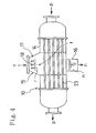
- a portion of the body 14 of a horizontal condenser 10 is increased in diameter, a condensate collector 16 is provided underneath this large-diameter portion 15, and in addition, condensate spray nozzles 18 are provided in the upper space (inlet) 17 of the large-diameter portion 15.
- the invention is configured such that, after drawing a portion of the condensate (n) in the condensate collector 16 by using a first pump 19, circulating water (r) is injected into the steam (f) in the upper space (inlet) 17 of the condenser 10, the circulating water (r) being sprayed from the above condensate spray nozzles 18.
- the circulating water (r) is generated from the condensate (n) via the heat exchanger 11 already described.
- the heat transfer area of the heat transfer tubes 23 can be made smaller than that of a conventional condenser (i.e., a condenser using only seawater for heating/cooling).
- the majority of the circulating water (r) is pumped out by a second pump 20, flows into a condensation chamber 21, and is subsequently fed into the waste heat boiler 6 by a condensate recovery pump 22.
- 25 is a recovered water pump
- 26 is a decomposition tank fluid recirculation pump
- 27 is a cooling water pump.
- Fig. 5 illustrates the heat and material balance in a gasification tank that feeds 50 t/h natural gas into a gas turbine combustion chamber.
- Gas hydrate (h) in pellet form in a storage tank 31 is first finely crushed by a crusher (not shown in the drawings), and subsequently fed into a mixer 34 by a rotary valve 33 (feed rate: 375 t/h, temperature: -20 °C).
- Gas hydrate (h) (approx. 10 mm) in the mixer 34 is slurried (slurry concentration: 0.2 %) by water (i) (circulating water) (water temperature: 10 °C, pressure: 3 ata (0.29 MPa), feed rate: 1,499 t/h) supplied from a gasification tank 32.
- the slurry is then fed into the gasification tank 32 by a slurry pump 35.
- the gasification tank 32 has an operating temperature of 10 °C and an operating pressure of 35 ata (3.43 MPa), wherein water (i) (circulating water) at the operating temperature is circulated (4,565 t/h), the water (i) being heated in an external heat exchanger 11, using circulating water (r) as a heat source.
- the heated water (i) (circulating water) (20 °C) is then sprayed into the tank from spray nozzles 36.
- the amount of the dissociated water (m) is 325 t/h.
- the amount of natural gas is 50 t/h plus some amount (0.0179 t/h) in the form of moisture-saturated gas, these amounts corresponding to the quantity of gas hydrate that was loaded into the tank.
- Fig. 6 illustrates the heat and material balance in an improved steam turbine condenser.
- the condenser 10 drain rate: 388 t/h, entropy: 33.0 kcal/kg
- seawater for cooling
- feed rate 23,298 t/h
- the condenser is modified to recirculate (circulation rate: 5,706 t/h) and spray drain.
- the gas hydrate decomposition heat corresponds to 21.4 % of the heat load of the condenser.
Landscapes
- Engineering & Computer Science (AREA)
- Mechanical Engineering (AREA)
- General Engineering & Computer Science (AREA)
- Chemical & Material Sciences (AREA)
- Combustion & Propulsion (AREA)
- Physics & Mathematics (AREA)
- Thermal Sciences (AREA)
- Engine Equipment That Uses Special Cycles (AREA)
Applications Claiming Priority (1)
| Application Number | Priority Date | Filing Date | Title |
|---|---|---|---|
| PCT/JP2006/307977 WO2007122692A1 (fr) | 2006-04-14 | 2006-04-14 | Procédé de décomposition d'un hydrate de gaz et appareil prévu à cet effet dans un système générateur d'électricité combiné à une turbine à gaz |
Publications (2)
| Publication Number | Publication Date |
|---|---|
| EP2009253A1 true EP2009253A1 (fr) | 2008-12-31 |
| EP2009253A4 EP2009253A4 (fr) | 2014-03-12 |
Family
ID=38624624
Family Applications (1)
| Application Number | Title | Priority Date | Filing Date |
|---|---|---|---|
| EP06731913.7A Withdrawn EP2009253A4 (fr) | 2006-04-14 | 2006-04-14 | Procédé de décomposition d'un hydrate de gaz et appareil prévu à cet effet dans un système générateur d'électricité combiné à une turbine à gaz |
Country Status (3)
| Country | Link |
|---|---|
| US (1) | US20090260362A1 (fr) |
| EP (1) | EP2009253A4 (fr) |
| WO (1) | WO2007122692A1 (fr) |
Families Citing this family (3)
| Publication number | Priority date | Publication date | Assignee | Title |
|---|---|---|---|---|
| US20080072495A1 (en) * | 1999-12-30 | 2008-03-27 | Waycuilis John J | Hydrate formation for gas separation or transport |
| DE102011108065A1 (de) * | 2011-07-21 | 2013-01-24 | Rwe Ag | Verfahren zur energetischen Nutzung von Brenngasen |
| CN110701013A (zh) * | 2019-11-08 | 2020-01-17 | 中国石油大学(北京) | 温差发电系统及温差发电方法 |
Family Cites Families (9)
| Publication number | Priority date | Publication date | Assignee | Title |
|---|---|---|---|---|
| US3820334A (en) * | 1972-07-28 | 1974-06-28 | Transelektro Magyar Villamossa | Heating power plants |
| FR2378944A1 (fr) * | 1977-01-27 | 1978-08-25 | Fives Cail Babcock | Dispositif pour le refroidissement de la vapeur detendue par une turbine |
| US4506508A (en) * | 1983-03-25 | 1985-03-26 | Chicago Bridge & Iron Company | Apparatus and method for condensing steam |
| JPH11200884A (ja) | 1998-01-19 | 1999-07-27 | Mitsubishi Heavy Ind Ltd | ガスタービン設備、及び同ガスタービン設備を含む液化天然ガス複合サイクル発電プラント |
| US6298652B1 (en) * | 1999-12-13 | 2001-10-09 | Exxon Mobil Chemical Patents Inc. | Method for utilizing gas reserves with low methane concentrations and high inert gas concentrations for fueling gas turbines |
| JPWO2002077515A1 (ja) * | 2001-03-06 | 2004-07-15 | 三井造船株式会社 | ガス供給事業における電力平準化方法及びメタンハイドレート冷熱利用発電システム |
| JP2002371862A (ja) | 2001-06-14 | 2002-12-26 | Ishikawajima Harima Heavy Ind Co Ltd | コージェネレーションシステム施設 |
| JP2003324994A (ja) * | 2002-04-26 | 2003-11-14 | Mitsubishi Heavy Ind Ltd | エネルギープラント |
| JP2006112345A (ja) * | 2004-10-15 | 2006-04-27 | Mitsui Eng & Shipbuild Co Ltd | ガスタービン複合発電システムにおけるガスハイドレート分解方法及び装置 |
-
2006
- 2006-04-14 EP EP06731913.7A patent/EP2009253A4/fr not_active Withdrawn
- 2006-04-14 US US12/226,275 patent/US20090260362A1/en not_active Abandoned
- 2006-04-14 WO PCT/JP2006/307977 patent/WO2007122692A1/fr not_active Ceased
Also Published As
| Publication number | Publication date |
|---|---|
| WO2007122692A1 (fr) | 2007-11-01 |
| EP2009253A4 (fr) | 2014-03-12 |
| US20090260362A1 (en) | 2009-10-22 |
Similar Documents
| Publication | Publication Date | Title |
|---|---|---|
| EP0551876B1 (fr) | Procédé pour éliminer de dioxyde de carbone de gaz de combustion | |
| CN1052053C (zh) | 一种改进的以液化天然气为燃料的联合循环发电设备 | |
| CN1671463A (zh) | 低排放热电厂 | |
| CN102859147B (zh) | 清除联合循环发电系统中的夹带气体的方法 | |
| CN111952642A (zh) | 高效低振噪燃料电池发电系统 | |
| US20230258105A1 (en) | Combined power generation system and driving method thereof | |
| US11988114B2 (en) | H2 boiler for steam system | |
| KR102174013B1 (ko) | 미활용 중저온 폐열을 이용한 orc 발전시스템 | |
| CN114810252A (zh) | 一种超临界co2发电机组变负荷工质充排系统及方法 | |
| CN102230400A (zh) | 一种利用蒸汽透平排出乏汽发电的装置 | |
| WO2009031747A1 (fr) | Centrale électrique ayant une chambre de combustion à oxygène pur | |
| EP0831205A2 (fr) | Système de production d'énergie capable de la séparation et de la récupération du dioxyde de carbone | |
| EP2009253A1 (fr) | Procédé de décomposition d'un hydrate de gaz et appareil prévu à cet effet dans un système générateur d'électricité combiné à une turbine à gaz | |
| JP2006112345A (ja) | ガスタービン複合発電システムにおけるガスハイドレート分解方法及び装置 | |
| EP2251626A2 (fr) | Compression efficace d'azote dans une centrale électrique à cycle combiné | |
| KR20090008124A (ko) | 이중 압력 다단계 전기 분해를 이용하는 수소 생성 공정 | |
| CN211204067U (zh) | 一种船舶天然气焚烧装置废热回收系统 | |
| RU2247446C2 (ru) | Способ эксплуатации энергоустановки на основе электрохимического генератора и устройство реализации способа | |
| CN114935112B (zh) | 一种lng固体氧化物燃料电池动力船烟气回收系统 | |
| JP2000133295A (ja) | 固体電解質燃料電池複合発電プラントシステム | |
| JP3059124B2 (ja) | 水素燃焼タービンプラント | |
| EP3410013B1 (fr) | Système de distribution de gaz de combustion | |
| CN115288960B (zh) | 耦合太阳能的汽轮机系统和发电系统 | |
| CN220185193U (zh) | 一种联合发电系统 | |
| US12595761B2 (en) | Generating electrical energy from hydrogen and oxygen |
Legal Events
| Date | Code | Title | Description |
|---|---|---|---|
| PUAI | Public reference made under article 153(3) epc to a published international application that has entered the european phase |
Free format text: ORIGINAL CODE: 0009012 |
|
| 17P | Request for examination filed |
Effective date: 20081021 |
|
| AK | Designated contracting states |
Kind code of ref document: A1 Designated state(s): AT BE BG CH CY CZ DE DK EE ES FI FR GB GR HU IE IS IT LI LT LU LV MC NL PL PT RO SE SI SK TR |
|
| AX | Request for extension of the european patent |
Extension state: AL BA HR MK YU |
|
| DAX | Request for extension of the european patent (deleted) | ||
| A4 | Supplementary search report drawn up and despatched |
Effective date: 20140206 |
|
| RIC1 | Information provided on ipc code assigned before grant |
Ipc: F28B 5/00 20060101ALI20140131BHEP Ipc: F01K 9/00 20060101AFI20140131BHEP Ipc: F02C 3/28 20060101ALI20140131BHEP Ipc: F01K 23/10 20060101ALI20140131BHEP Ipc: C10L 3/06 20060101ALI20140131BHEP |
|
| STAA | Information on the status of an ep patent application or granted ep patent |
Free format text: STATUS: THE APPLICATION IS DEEMED TO BE WITHDRAWN |
|
| 18D | Application deemed to be withdrawn |
Effective date: 20140909 |