EP2009273A1 - Rollerartiges Fahrzeug - Google Patents
Rollerartiges Fahrzeug Download PDFInfo
- Publication number
- EP2009273A1 EP2009273A1 EP08154012A EP08154012A EP2009273A1 EP 2009273 A1 EP2009273 A1 EP 2009273A1 EP 08154012 A EP08154012 A EP 08154012A EP 08154012 A EP08154012 A EP 08154012A EP 2009273 A1 EP2009273 A1 EP 2009273A1
- Authority
- EP
- European Patent Office
- Prior art keywords
- air cleaner
- storage box
- air
- scooter
- type vehicle
- Prior art date
- Legal status (The legal status is an assumption and is not a legal conclusion. Google has not performed a legal analysis and makes no representation as to the accuracy of the status listed.)
- Granted
Links
- 239000002828 fuel tank Substances 0.000 claims abstract description 15
- 238000013459 approach Methods 0.000 claims abstract description 6
- 230000005540 biological transmission Effects 0.000 description 4
- 239000000428 dust Substances 0.000 description 4
- 238000001914 filtration Methods 0.000 description 2
- 230000008878 coupling Effects 0.000 description 1
- 238000010168 coupling process Methods 0.000 description 1
- 238000005859 coupling reaction Methods 0.000 description 1
- 230000002708 enhancing effect Effects 0.000 description 1
- 239000000446 fuel Substances 0.000 description 1
- XLYOFNOQVPJJNP-UHFFFAOYSA-N water Substances O XLYOFNOQVPJJNP-UHFFFAOYSA-N 0.000 description 1
Images




Classifications
-
- F—MECHANICAL ENGINEERING; LIGHTING; HEATING; WEAPONS; BLASTING
- F02—COMBUSTION ENGINES; HOT-GAS OR COMBUSTION-PRODUCT ENGINE PLANTS
- F02M—SUPPLYING COMBUSTION ENGINES IN GENERAL WITH COMBUSTIBLE MIXTURES OR CONSTITUENTS THEREOF
- F02M35/00—Combustion-air cleaners, air intakes, intake silencers, or induction systems specially adapted for, or arranged on, internal-combustion engines
- F02M35/02—Air cleaners
- F02M35/04—Air cleaners specially arranged with respect to engine, to intake system or specially adapted to vehicle; Mounting thereon ; Combinations with other devices
-
- F—MECHANICAL ENGINEERING; LIGHTING; HEATING; WEAPONS; BLASTING
- F02—COMBUSTION ENGINES; HOT-GAS OR COMBUSTION-PRODUCT ENGINE PLANTS
- F02M—SUPPLYING COMBUSTION ENGINES IN GENERAL WITH COMBUSTIBLE MIXTURES OR CONSTITUENTS THEREOF
- F02M35/00—Combustion-air cleaners, air intakes, intake silencers, or induction systems specially adapted for, or arranged on, internal-combustion engines
- F02M35/10—Air intakes; Induction systems
- F02M35/10006—Air intakes; Induction systems characterised by the position of elements of the air intake system in direction of the air intake flow, i.e. between ambient air inlet and supply to the combustion chamber
- F02M35/10013—Means upstream of the air filter; Connection to the ambient air
-
- F—MECHANICAL ENGINEERING; LIGHTING; HEATING; WEAPONS; BLASTING
- F02—COMBUSTION ENGINES; HOT-GAS OR COMBUSTION-PRODUCT ENGINE PLANTS
- F02M—SUPPLYING COMBUSTION ENGINES IN GENERAL WITH COMBUSTIBLE MIXTURES OR CONSTITUENTS THEREOF
- F02M35/00—Combustion-air cleaners, air intakes, intake silencers, or induction systems specially adapted for, or arranged on, internal-combustion engines
- F02M35/16—Combustion-air cleaners, air intakes, intake silencers, or induction systems specially adapted for, or arranged on, internal-combustion engines characterised by use in vehicles
- F02M35/162—Motorcycles; All-terrain vehicles, e.g. quads, snowmobiles; Small vehicles, e.g. forklifts
Definitions
- the present invention relates to a scooter-type vehicle having an air cleaner provided above a power unit.
- scooter-type vehicle which includes a power unit swingably supported on a body frame, an air cleaner provided above the power unit, and a storage box provided above the air cleaner and below a seat (see, for example, Patent Document 1).
- JP-A No. H6-117338 ( Figs. 1 and 4 )
- a power unit 13 including an engine 14 is swingably provided to a body frame 2 (Reference numerals used in the same publication will be used. The same applies hereinafter.) .
- an air cleaner 20 is connected to the rear via a carburetor 19.
- the air cleaner 20 is arranged from the front to above a rear wheel 16, on the rear side of an item storage member 7 (hereinafter, also referred to as the storage box 7) arranged below a sitting seat 8 (hereinafter, also referred to as the seat 8).
- the air cleaner 20 is integrally provided above a fender portion 21 of the rear wheel.
- the upper portion of the air cleaner 20 is covered by a cleaner case cover portion 25.
- a step is provided in the rear portion of the cleaner case cover portion 25, and an opening is provided in this step. That is, the cleaner case cover portion 25 is provided with an air reservoir in which sucked air is accumulated.
- the cleaner case cover portion 25 It is necessary to secure an air reservoir (dirty chamber) within the cleaner case cover portion 25 in order to secure a predetermined intake performance.
- the cleaner case cover portion 25 has to be enlarged naturally. As the size of the cleaner case cover portion 25 becomes larger, so do the height of the cleaner case cover portion 25 and the height of the air cleaner 20.
- a scooter-type vehicle including a body frame, a power unit swingably supported on the body frame, a storage box arranged above the power unit and below a seat on which an occupant sits, and an air cleaner that is arranged so as to overlap a rear portion of the storage box as seen from above and between the power unit and the storage box as seen from a lateral side and that is supported on the power unit, in which: the air cleaner includes an element that divides an inner portion of the air cleaner into a front side and a rear side to define a cleaner chamber on the front side and a dirty chamber on the rear side and filters outside air, an intake port that opens at an upper surface of the dirty chamber and sucks outside air into the dirty chamber, and a duct that is mounted to the intake port and extended toward the front of the vehicle to introduce outside air to the intake port; and a distal end portion of the duct is arranged in rear of a rear end portion of the storage box.
- the fuel tank is arranged in rear of the storage box, and a gap is provided between a rear side surface of the storage box and a front side surface of the fuel tank, and when the power unit swings and the air cleaner approaches the storage box, the duct is located near the gap.
- the body frame includes a secondary air supply device that supplies air to exhaust parts of an engine, and the air cleaner integrally includes on its lateral side a secondary air cleaner as a component of the secondary air supply device.
- a secondary air control unit that controls a quantity of secondary air includes an air introduction pipe, and the air introduction pipe is fitted and supported on a front surface of the secondary air cleaner.
- the secondary air control unit is supported on the air cleaner via a support stay that is a separate member mounted to a front surface of the air cleaner.
- the air cleaner includes an element that divides the inner portion of the air cleaner into a clean chamber on the front side and a dirty chamber on the rear side, and filters outside air. Therefore, as compared with a case where the dirty chamber is formed above the element, the volume required of the upper portion of the air cleaner can be made small. It is thus possible to ensure that the air cleaner has a required and sufficient intake performance, while making the volume required of the upper portion of the air cleaner small.
- an intake port that opens at the upper surface of the dirty chamber and sucks outside air into the dirty chamber, and a duct that is mounted to the intake port and extended toward the front of the vehicle to introduce outside air to the intake port are provided. Therefore, as compared with a case where the opening of the duct faces toward the rear of the vehicle, it is possible to significantly reduce intrusion of dust.
- the distal end portion of the duct is arranged in rear of the rear end portion of the storage box.
- a sufficiently large space is thus obtained between the air cleaner and the storage box, thereby making it possible to secure a sufficient volume of the storage box. Therefore, it is possible to ensure that the air cleaner has a required and sufficient intake performance, and also ensure that the storage box has a sufficient storage capacity.
- a gap is provided between a rear side surface of the storage box and a front side surface of the fuel tank, and when the air cleaner approaches the storage box, the duct is located near the gap.
- the secondary air cleaner in a case where the secondary air cleaner is provided, the secondary air cleaner is provided on the lateral side of the air cleaner, so its influence on the arrangement of the storage box can be reduced.
- an air introduction pipe is provided between the secondary air cleaner and the second air control unit, and the air introduction pipe is fitted and supported on the front surface of the secondary air cleaner.
- the secondary air control unit is not arranged above the air cleaner and is hence less likely to affect the size, arrangement, and the like of the storage box. In addition, it is possible to secure a sufficiently large volume of the storage box. Since the secondary air control unit is fitted and supported on the front surface of the secondary air cleaner via the air introduction pipe, the secondary air control unit can be supported in place by means of a simple structure.
- the secondary air control unit is supported in place via a support stay mounted to the air cleaner, so its influence on the size, arrangement, and the like of the storage box can be further reduced.
- the secondary air control unit can be supported in place with greater reliably.
- FIG. 1 is a left side view of a scooter-type vehicle according to the present invention.
- a motorcycle 10 as the scooter-type vehicle is a vehicle having a power unit 15 swingably mounted on a body frame 11 via a link mechanism 14 including a pivot shaft 12 in a rear portion of the body frame 11.
- the power unit 15 includes an engine 16 as a drive source, and a transmission case 17 provided in rear of the engine 16.
- a belt-type continuously variable transmission 18 for transmitting the drive force of the engine 16 to a rear wheel 19 is built in the transmission case 17.
- the transmission case 17 is swingably provided at the rear end portion of the body frame 11 so as to transmit the power of the engine 16 to the rear wheel 19.
- the motorcycle 10 has a front fork 26 steerably mounted to a head pipe 21, a front wheel 28 mounted to the lower end of the front fork 26, and a steering handlebar 29 mounted to the upper portion of the front fork 26.
- the rear wheel 19 is mounted to the rear end of the power unit 15 which doubles as a rear swing arm.
- a rear cushion unit 31 is suspended between the rear portion of the power unit 15 and a frame 24L.
- the link mechanism 14 interposed between the power unit 15 and a cross member 23 includes a support shaft 32 provided near the cross member 23, a link member 33 extending rearward from the support shaft 32, and the pivot shaft 12 provided at the rear end portion of the link member 33.
- An intake device 38 and an exhaust device 39 are connected to a cylinder block 37 of the engine 16 which constitutes the front portion of the power unit 15.
- the intake device 38 includes an air cleaner 41, and a fuel supply device 42 connected to the air cleaner 41 via a coupling member 40.
- the exhaust device 39 includes an exhaust pipe 43 connected to the engine 16 and extended rearward, and a muffler 44 connected to the exhaust pipe 43 and extended rearward.
- a storage box 45 that opens upward is provided to seat frames 24L, 24R.
- a seat 46 on which an occupant sits straddling is provided above the storage box 45.
- a fuel tank 47 is arranged in rear of the storage box 45. The seat 46 is mounted from above the storage box 45 and the fuel tank 47 so as to be capable of opening and closing.
- Reference numeral 48 denotes a step floor support frame that supports a step floor 49, 51 a passenger footrest support frame, 53 a grab rail, 54 a front brake unit, 55 a front fender, 56 a cowl member, 57 a rear fender, and 58 a side stand.
- the motorcycle 10 as a scooter-type vehicle includes the body frame 11, the steering handlebar 29 and the seat 46 for the occupant to sit on, which are supported on the vehicle frame 11, and the step floor 49 provided between the steering handlebar 29 and the seat 46 and on which the occupants places his/her feet.
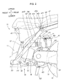
- Fig. 2 is a main-portion left side view of the scooter-type vehicle according to the present invention
- Fig. 3 is a plan view illustrating the positional relationship between the storage box and air cleaner of the scooter-type vehicle according to the present invention.
- reference will be made to Figs. 2 and 3 .
- the body frame 11 includes the cross member 23 mounted to the rear end portion of a down frame 22 in the width direction of the vehicle, the left and right seat frames 24L, 24R that rise obliquely rearward from the left and right ends of the cross member 23, a cross frame 61 that is suspended intermediate between the left and right seat frames 24L, 24R to support the storage box 45, a seat cross frame 62 arranged in rear of the cross frame 61 and suspended intermediate between the left and right seat frames 24L, 24R to support the seat 46, and a rear cross member 63 suspended between the rear end portions of the left and right seat frames 24L, 24R.
- a stop lamp unit 65 is mounted to the rear end portions of the seat frames 24L, 24R. A detailed description of the stop lamp unit 65 will be given later.
- the motorcycle 10 as the scooter-type vehicle includes the body frame 11, the power unit 15 swingably supported on the body frame 11 via the link mechanism 14, the storage box 45 arranged above the power unit 15 and below the seat 46 on which the occupant sits, and the air cleaner 41 that is arranged so as to overlap a rear portion 45c of the storage box 45 as seen from above and located between the power unit 15 and the storage box 45 as seen from the lateral side.
- the air cleaner 41 is supported by a bracket 66 provided on the upper surface of the power unit 15. That is, the air cleaner 41 is a member that swings following the swing motion of the power unit 15.
- the fuel tank 47 is arranged in rear of the storage box 45.
- a gap 68 is provided between a rear side surface 45r of the storage box 45 and a front side surface 47f of the fuel tank 47.
- a distal end portion 71f of a duct 71 for admitting outside air to the air cleaner 41 is arranged in rear of a rear end portion 45b of the storage box 45.
- the body frame 11 includes a secondary air supply device 72.
- the secondary air supply device 72 has a function of, for example, supplying air to exhaust parts of the engine 16 such as the exhaust pipe 43 and the muffler 44, and burning the combustible components in an exhaust gas to purify the exhaust gas.
- the secondary air supply device 72 includes, as its main components, a secondary air cleaner 73 for filtering sucked air, and a secondary air control unit 74 as a valve for supplying the air sucked in through the air cleaner 73 to the exhaust parts according to predetermined conditions.
- the secondary air cleaner 73 is provided on the lateral side of the air cleaner 41, so its influence on the arrangement of the storage box 45 can be reduced.
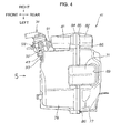
- Fig. 4 is a plan view of the air cleaner and second air supply device of the scooter-type vehicle according to the present invention.
- Fig. 5 is a view as seen from the arrow 5 of Fig. 4
- Fig. 6 is a main-portion sectional view of the air cleaner and second air supply device of the scooter-type vehicle according to the present invention.
- Figs. 4 to 6 reference will be made to Figs. 4 to 6 .
- the air cleaner 41 includes a front case 76 and a rear case 77, and an element 78 that is arranged between the front case 76 and the rear case 77 and filters outside air.
- a front sub-case 81 as a component of the secondary air cleaner 73 described later is integrally formed in the front case 76.
- a rear sub-case 82 as a component of the secondary air cleaner 73 is integrally formed in the rear case 77.
- a subelement 83 for filtering outside air is arranged between the front sub-case 81 and the rear sub-case 82.
- the front case 76 and the rear case 77 are butted together at flange portions 84, 85.
- the flange portions 84, 85 are fixed in place with a plurality of mounting bolts 86.
- the inner portion of the air cleaner 41 is divided into the front and rear sides by the element 78, with a clean chamber 87 and a dirty chamber 88 formed on the front and rear sides of the air cleaner 41, respectively.
- the air cleaner 41 has an intake port 89 that opens at the upper surface of the dirty chamber 88 and sucks outside air into the dirty chamber 88.
- Mounted to the intake port 89 is the duct 71 that is extended toward the front of the vehicle and introduces outside air to the intake port 89.
- An air introduction pipe 91 is coupled to the front portion of the front sub-case 81.
- the secondary air control unit 74 for controlling the quantity of secondary air is mounted to the air introduction pipe 91.
- the air introduction pipe 91 is equipped to the secondary air control unit 74.
- the air introduction pipe 91 is fitted and supported on the front surface of the secondary air cleaner 73.
- the secondary air control unit 74 is not arranged above the air cleaner 41 and is hence less likely to affect the size, arrangement, and the like of the storage box (indicated by reference numeral 45 in Fig. 2 ). In addition, it is possible to secure a sufficiently large volume of the storage box 45.
- the secondary air control unit 74 Since the secondary air control unit 74 is fitted and supported on the front surface of the secondary air cleaner 73 via the air introduction pipe 91, the secondary air control unit 74 can be supported in place by means of a simple structure.
- a support stay 92 having a platelike shape is mounted to a front surface 41f of the air cleaner 41 via bolts 93.
- the other end of the support stay 92 is mounted to the secondary air control unit 74 via the bolts 93. That is, the secondary air control unit 74 is supported on the air cleaner 41 via the support stay 92 that is a separate member mounted to the front surface 41f of the air cleaner 41.
- the secondary air control unit 74 is supported on the air cleaner 41 via the support stay 92 formed in the shape of a mounting plate. Since the support stay 92 occupies only a limited space, its influence on the size, arrangement, and the like of the storage box 45 can be further reduced. In addition, the secondary air control unit 74 can be supported in place with greater reliably.
- the dirty chamber 88 is formed in rear of the element 78. Therefore, as compared with a case where the dirty chamber 88 is formed above the element 78, the volume required of the upper portion of the air cleaner 41 can be made small. It is thus possible to ensure that the air cleaner 41 has a required and sufficient intake performance, while making the volume required of the upper portion of the air cleaner 41 small.
- the intake port 89 that opens at the upper surface of the dirty chamber 88 and sucks outside air into the dirty chamber 88
- the duct 71 that is mounted to the intake port 89 and extended toward the front of the vehicle to introduce outside air to the intake port 89 are provided. Therefore, as compared with a case where the opening of the duct 71 faces toward the rear of the vehicle, it is possible to significantly reduce intrusion of dust.
- the distal end portion 71t of the duct is arranged in rear of the rear end portion 45b of the storage box.
- a sufficiently large space is thus obtained between the air cleaner 41 and the storage box 45, thereby making it possible to secure a sufficient volume of the storage box 45. Therefore, it is possible to ensure that the air cleaner 41 has a required and sufficient intake performance, and also ensure that the storage box 45 has a sufficient storage capacity.
- the freedom in terms of the structure and arrangement of the air cleaner 41 can be enhanced.
- the structure of the air cleaner 41 for example, it is possible to ensure that the dirty chamber 88 of the air cleaner 41 has a sufficient volume. In addition, it is possible to secure a sufficient volume of the storage box 45.
- Fig. 7 is an operational view of Fig. 2 .
- the duct 71 is located near the gap 68.
- the gap 68 is provided between the rear side surface 45r of the storage box 45 and the front side surface 47f of the fuel tank 47, and when the air cleaner 41 approaches the storage box 45, the duct 71 is located near the gap 68.
- FIG. 8 is a left side view of a rear stop lamp unit of the scooter-type vehicle according to the present invention
- Fig. 9 is a view as seen from the arrow 9 of Fig. 8 .
- a rear stop lamp unit 65 is a member that constitutes the appearance of the rear end portion of the vehicle.
- the rear stop lamp unit 65 includes a main body portion 96, an upper portion 97 that covers the top of the main body portion 96, and a rear portion 98 that covers the rear of the main body portion 96.
- the rear portion 98 has a tail lamp 99 arranged at its center, and left and right winker lamps 101L, 101R arranged on the left and right of the tail lamp 99, with the tail lamp 99 and the winker lamps 101L, 101R covered by lenses 102, 103L, 103R, respectively.
- the rear stop lamp unit 65 is mounted to the left and right seat frames 24L, 24R via bolts 104.
- the upper portion 97 included in the rear stop lamp unit 65 is exposed outward and constitutes a part of the appearance design of the vehicle.
- the upper portion 97 of the rear stop lamp unit 65 is used such that the upper portion 97 is exposed as a part of the appearance design. Therefore, it is possible to reduce the number of parts while enhancing the appearance of the vehicle.
- the gap provided between the rear side surface of the storage box and the front side surface of the fuel tank may be omitted.
- the secondary air supply device may be omitted.
- the present invention is suitably applicable to a scooter-type vehicle.
Landscapes
- Engineering & Computer Science (AREA)
- Chemical & Material Sciences (AREA)
- Combustion & Propulsion (AREA)
- Mechanical Engineering (AREA)
- General Engineering & Computer Science (AREA)
- Automatic Cycles, And Cycles In General (AREA)
- Exhaust Gas After Treatment (AREA)
Applications Claiming Priority (1)
| Application Number | Priority Date | Filing Date | Title |
|---|---|---|---|
| JP2007171070A JP5002351B2 (ja) | 2007-06-28 | 2007-06-28 | スクータ型車両 |
Publications (2)
| Publication Number | Publication Date |
|---|---|
| EP2009273A1 true EP2009273A1 (de) | 2008-12-31 |
| EP2009273B1 EP2009273B1 (de) | 2011-12-07 |
Family
ID=39627358
Family Applications (1)
| Application Number | Title | Priority Date | Filing Date |
|---|---|---|---|
| EP20080154012 Ceased EP2009273B1 (de) | 2007-06-28 | 2008-04-03 | Rollerartiges Fahrzeug |
Country Status (4)
| Country | Link |
|---|---|
| EP (1) | EP2009273B1 (de) |
| JP (1) | JP5002351B2 (de) |
| CN (1) | CN101333987B (de) |
| MY (1) | MY151514A (de) |
Cited By (1)
| Publication number | Priority date | Publication date | Assignee | Title |
|---|---|---|---|---|
| US8919480B2 (en) | 2011-09-16 | 2014-12-30 | Yamaha Hatsudoki Kabushiki Kaisha | Motorcycle |
Families Citing this family (5)
| Publication number | Priority date | Publication date | Assignee | Title |
|---|---|---|---|---|
| CN106170436B (zh) * | 2014-03-31 | 2019-07-02 | 本田技研工业株式会社 | 用于摩托车的控制单元安装结构 |
| DE102014217388A1 (de) * | 2014-09-01 | 2016-03-03 | Robert Bosch Gmbh | Kraftstoffhochdruckpumpe, insbesondere für eine Kraftstoffeinspritzeinrichtung einer Brennkraftmaschine |
| DE102017204925B3 (de) * | 2017-03-23 | 2018-09-13 | Continental Automotive Gmbh | Ventilanordnung für ein Kraftstoffeinspritzsystem sowie Kraftstoffeinspritzsystem |
| JP7251312B2 (ja) * | 2019-05-24 | 2023-04-04 | スズキ株式会社 | 車両の吸気構造 |
| JP7251311B2 (ja) * | 2019-05-24 | 2023-04-04 | スズキ株式会社 | 車両の吸気構造 |
Citations (4)
| Publication number | Priority date | Publication date | Assignee | Title |
|---|---|---|---|---|
| JPS5949360A (ja) | 1982-09-14 | 1984-03-21 | Honda Motor Co Ltd | 自動二輪車等の吸気装置 |
| JP2001063665A (ja) * | 1999-08-31 | 2001-03-13 | Yamaha Motor Co Ltd | スクータ型自動二輪車用エアクリーナ |
| EP1619112A1 (de) | 2004-07-19 | 2006-01-25 | Kwang Yang Motor Co., Ltd. | Anordnung eines Luftfilters für Motorroller |
| US20060124379A1 (en) | 2004-11-22 | 2006-06-15 | Masaru Ohira | System for accessing an air box in a straddle type vehicle |
Family Cites Families (7)
| Publication number | Priority date | Publication date | Assignee | Title |
|---|---|---|---|---|
| JP3231400B2 (ja) * | 1992-05-22 | 2001-11-19 | 本田技研工業株式会社 | 自動二輪車の2次空気供給装置 |
| JP3932439B2 (ja) * | 1997-04-24 | 2007-06-20 | 本田技研工業株式会社 | 小型自動二輪車の排気系への2次空気供給装置 |
| JP3697886B2 (ja) * | 1998-04-15 | 2005-09-21 | スズキ株式会社 | スクータ型自動二輪車 |
| JP4240431B2 (ja) * | 1999-09-24 | 2009-03-18 | 本田技研工業株式会社 | 自動二輪車のエアクリーナ装置 |
| JP3970517B2 (ja) * | 2000-12-28 | 2007-09-05 | 本田技研工業株式会社 | 車両のエアクリーナ構造 |
| JP3890898B2 (ja) * | 2001-02-13 | 2007-03-07 | スズキ株式会社 | スクータ型自動二輪車の2次空気供給装置 |
| JP4133282B2 (ja) * | 2002-12-10 | 2008-08-13 | 本田技研工業株式会社 | スクータ型車両のエアクリーナの配置構造 |
-
2007
- 2007-06-28 JP JP2007171070A patent/JP5002351B2/ja not_active Expired - Fee Related
-
2008
- 2008-04-03 EP EP20080154012 patent/EP2009273B1/de not_active Ceased
- 2008-05-21 CN CN200810107941XA patent/CN101333987B/zh not_active Expired - Fee Related
- 2008-06-24 MY MYPI20082307 patent/MY151514A/en unknown
Patent Citations (4)
| Publication number | Priority date | Publication date | Assignee | Title |
|---|---|---|---|---|
| JPS5949360A (ja) | 1982-09-14 | 1984-03-21 | Honda Motor Co Ltd | 自動二輪車等の吸気装置 |
| JP2001063665A (ja) * | 1999-08-31 | 2001-03-13 | Yamaha Motor Co Ltd | スクータ型自動二輪車用エアクリーナ |
| EP1619112A1 (de) | 2004-07-19 | 2006-01-25 | Kwang Yang Motor Co., Ltd. | Anordnung eines Luftfilters für Motorroller |
| US20060124379A1 (en) | 2004-11-22 | 2006-06-15 | Masaru Ohira | System for accessing an air box in a straddle type vehicle |
Cited By (1)
| Publication number | Priority date | Publication date | Assignee | Title |
|---|---|---|---|---|
| US8919480B2 (en) | 2011-09-16 | 2014-12-30 | Yamaha Hatsudoki Kabushiki Kaisha | Motorcycle |
Also Published As
| Publication number | Publication date |
|---|---|
| EP2009273B1 (de) | 2011-12-07 |
| JP5002351B2 (ja) | 2012-08-15 |
| CN101333987A (zh) | 2008-12-31 |
| CN101333987B (zh) | 2011-12-14 |
| MY151514A (en) | 2014-05-30 |
| JP2009006909A (ja) | 2009-01-15 |
Similar Documents
| Publication | Publication Date | Title |
|---|---|---|
| EP2009273A1 (de) | Rollerartiges Fahrzeug | |
| JP2007314165A (ja) | 自動二輪車 | |
| CN105275680A (zh) | 鞍骑型车辆的空气滤清器装置 | |
| JP2008290712A (ja) | ライダーサドルおよび燃料タンクを有する自動二輪車 | |
| CN104421070B (zh) | 摩托车型车辆 | |
| EP1972534B1 (de) | Motorrad | |
| CN102691600A (zh) | 空气滤清器结构 | |
| EP1772359A1 (de) | Motorrad | |
| CN103129662A (zh) | 踏板车型摩托车 | |
| JP5778947B2 (ja) | 鞍乗り型車両の排気浄化装置 | |
| KR100891781B1 (ko) | 차량용 무단 변속기의 냉각 구조 | |
| JP5259561B2 (ja) | 鞍乗型車両 | |
| CN111183276A (zh) | 排气传感器的安装结构 | |
| JP2015068212A (ja) | 小型車両の吸気装置 | |
| JP4969969B2 (ja) | 揺動式自動三輪車におけるエアクリーナの空気導入構造 | |
| JP4847508B2 (ja) | スクータ型車両 | |
| CN1603607B (zh) | 燃料泵壳体 | |
| JP7707139B2 (ja) | 鞍乗型車両 | |
| CN104602999B (zh) | 踏板型车辆 | |
| JP5205231B2 (ja) | 鞍乗り型車両 | |
| JP7157259B2 (ja) | 鞍乗型車両 | |
| JP2002242670A (ja) | スクータ型自動二輪車の2次空気供給装置 | |
| CN1749093A (zh) | 二轮机动车 | |
| JP4386304B2 (ja) | スクータ型自動二輪車 | |
| JP4197355B2 (ja) | スクータ型車両 |
Legal Events
| Date | Code | Title | Description |
|---|---|---|---|
| PUAI | Public reference made under article 153(3) epc to a published international application that has entered the european phase |
Free format text: ORIGINAL CODE: 0009012 |
|
| 17P | Request for examination filed |
Effective date: 20080403 |
|
| AK | Designated contracting states |
Kind code of ref document: A1 Designated state(s): AT BE BG CH CY CZ DE DK EE ES FI FR GB GR HR HU IE IS IT LI LT LU LV MC MT NL NO PL PT RO SE SI SK TR |
|
| AX | Request for extension of the european patent |
Extension state: AL BA MK RS |
|
| 17Q | First examination report despatched |
Effective date: 20090218 |
|
| AKX | Designation fees paid |
Designated state(s): DE IT |
|
| GRAC | Information related to communication of intention to grant a patent modified |
Free format text: ORIGINAL CODE: EPIDOSCIGR1 |
|
| GRAP | Despatch of communication of intention to grant a patent |
Free format text: ORIGINAL CODE: EPIDOSNIGR1 |
|
| GRAS | Grant fee paid |
Free format text: ORIGINAL CODE: EPIDOSNIGR3 |
|
| GRAA | (expected) grant |
Free format text: ORIGINAL CODE: 0009210 |
|
| AK | Designated contracting states |
Kind code of ref document: B1 Designated state(s): DE IT |
|
| RIN2 | Information on inventor provided after grant (corrected) |
Inventor name: SAKANE, TAIKI Inventor name: FUNAYAMA, YOSHIHIRO Inventor name: KAMEMIZU, FUMINORI Inventor name: HARA, HIROKAZU |
|
| REG | Reference to a national code |
Ref country code: DE Ref legal event code: R096 Ref document number: 602008011812 Country of ref document: DE Effective date: 20120308 |
|
| PLBE | No opposition filed within time limit |
Free format text: ORIGINAL CODE: 0009261 |
|
| STAA | Information on the status of an ep patent application or granted ep patent |
Free format text: STATUS: NO OPPOSITION FILED WITHIN TIME LIMIT |
|
| 26N | No opposition filed |
Effective date: 20120910 |
|
| REG | Reference to a national code |
Ref country code: DE Ref legal event code: R097 Ref document number: 602008011812 Country of ref document: DE Effective date: 20120910 |
|
| PGFP | Annual fee paid to national office [announced via postgrant information from national office to epo] |
Ref country code: DE Payment date: 20180320 Year of fee payment: 11 |
|
| PGFP | Annual fee paid to national office [announced via postgrant information from national office to epo] |
Ref country code: IT Payment date: 20180420 Year of fee payment: 11 |
|
| REG | Reference to a national code |
Ref country code: DE Ref legal event code: R119 Ref document number: 602008011812 Country of ref document: DE |
|
| PG25 | Lapsed in a contracting state [announced via postgrant information from national office to epo] |
Ref country code: DE Free format text: LAPSE BECAUSE OF NON-PAYMENT OF DUE FEES Effective date: 20191101 |
|
| PG25 | Lapsed in a contracting state [announced via postgrant information from national office to epo] |
Ref country code: IT Free format text: LAPSE BECAUSE OF NON-PAYMENT OF DUE FEES Effective date: 20190403 |