EP2009287B1 - Dispositif et procédé d'échappement sous vide - Google Patents
Dispositif et procédé d'échappement sous vide Download PDFInfo
- Publication number
- EP2009287B1 EP2009287B1 EP08011531.4A EP08011531A EP2009287B1 EP 2009287 B1 EP2009287 B1 EP 2009287B1 EP 08011531 A EP08011531 A EP 08011531A EP 2009287 B1 EP2009287 B1 EP 2009287B1
- Authority
- EP
- European Patent Office
- Prior art keywords
- vacuum
- oil
- valve
- degree
- container
- Prior art date
- Legal status (The legal status is an assumption and is not a legal conclusion. Google has not performed a legal analysis and makes no representation as to the accuracy of the status listed.)
- Ceased
Links
Images

Classifications
-
- F—MECHANICAL ENGINEERING; LIGHTING; HEATING; WEAPONS; BLASTING
- F04—POSITIVE - DISPLACEMENT MACHINES FOR LIQUIDS; PUMPS FOR LIQUIDS OR ELASTIC FLUIDS
- F04D—NON-POSITIVE-DISPLACEMENT PUMPS
- F04D19/00—Axial-flow pumps
- F04D19/02—Multi-stage pumps
- F04D19/04—Multi-stage pumps specially adapted to the production of a high vacuum, e.g. molecular pumps
-
- F—MECHANICAL ENGINEERING; LIGHTING; HEATING; WEAPONS; BLASTING
- F04—POSITIVE - DISPLACEMENT MACHINES FOR LIQUIDS; PUMPS FOR LIQUIDS OR ELASTIC FLUIDS
- F04B—POSITIVE-DISPLACEMENT MACHINES FOR LIQUIDS; PUMPS
- F04B37/00—Pumps having pertinent characteristics not provided for in, or of interest apart from, groups F04B25/00 - F04B35/00
- F04B37/10—Pumps having pertinent characteristics not provided for in, or of interest apart from, groups F04B25/00 - F04B35/00 for special use
- F04B37/14—Pumps having pertinent characteristics not provided for in, or of interest apart from, groups F04B25/00 - F04B35/00 for special use to obtain high vacuum
- F04B37/16—Means for nullifying unswept space
-
- F—MECHANICAL ENGINEERING; LIGHTING; HEATING; WEAPONS; BLASTING
- F04—POSITIVE - DISPLACEMENT MACHINES FOR LIQUIDS; PUMPS FOR LIQUIDS OR ELASTIC FLUIDS
- F04B—POSITIVE-DISPLACEMENT MACHINES FOR LIQUIDS; PUMPS
- F04B49/00—Control, e.g. of pump delivery, or pump pressure of, or safety measures for, machines, pumps, or pumping installations, not otherwise provided for, or of interest apart from, groups F04B1/00 - F04B47/00
- F04B49/06—Control using electricity
-
- F—MECHANICAL ENGINEERING; LIGHTING; HEATING; WEAPONS; BLASTING
- F04—POSITIVE - DISPLACEMENT MACHINES FOR LIQUIDS; PUMPS FOR LIQUIDS OR ELASTIC FLUIDS
- F04C—ROTARY-PISTON, OR OSCILLATING-PISTON, POSITIVE-DISPLACEMENT MACHINES FOR LIQUIDS; ROTARY-PISTON, OR OSCILLATING-PISTON, POSITIVE-DISPLACEMENT PUMPS
- F04C25/00—Adaptations of pumps for special use of pumps for elastic fluids
- F04C25/02—Adaptations of pumps for special use of pumps for elastic fluids for producing high vacuum
Definitions
- the present invention relates to a vacuum-exhaust device and a vacuum-exhaust method for evacuating a vacuum container using an oil-rotary vacuum pump.
- the vacuum-exhaust device includes: a turbo-molecular pump for highly evacuating a vacuum container, the turbo-molecular pump connected to the vacuum container via an inlet valve; and an oil-rotary pump connected in series to the turbo-molecular pump.
- the vacuum-exhaust device further includes a container vacuometer for measuring a vacuum degree of the vacuum container and an exhaust vacuometer for measuring a vacuum degree of the turbo-molecular pump adjacent to the container.
- a controller controls a driving of the turbo-molecular pump and the oil-rotary pump and opening and closing of an exhaust valve and the inlet valve.
- an observation chamber of a scanning electron microscope which is used for observing a sample, is linked with a spare chamber repeatedly changed between an atmospheric state and a vacuum state through a gate valve.
- an oil-rotary pump which is connected to the observation chamber via a first rough-piping valve, is also connected to the spare chamber via a second rough-piping valve.
- a vacuometer and an arrangement for introducing gas in a small amount are provided between the spare chamber and the second rough-piping valve.
- JP H07197884A relates to an oil steam reverse flow preventing device for an evacuation line and discloses all of the features in the preamble of claim 1.
- JP 2006322405 relates to an evacuation system capable of stopping an evacuation device while preventing reverse flow of oil from the evacuation device.
- an object of the present invention is to provide a vacuum-exhaust device and a vacuum-exhaust method capable of reducing device cost in a simplified arrangement.
- the object is achieved by a vacuum-exhaust device according to claim 1 and a vacuum-exhaust method according to claim 10.
- a vacuum-exhaust device is a vacuum-exhaust device connected to a vacuum container and adapted to evacuate the vacuum container, the vacuum-exhaust device including: an oil-rotary vacuum pump connected to the vacuum container and adapted to evacuate the vacuum container; a pair of on-off valves provided in series between the vacuum container and the oil-rotary vacuum pump; and a vacuometer positioned between the pair of on-off valves and adapted to measure a vacuum degree.
- the pair of on-off valves are provided in series between the vacuum container and the oil-rotary vacuum pump for evacuating the vacuum container, and the vacuometer for measuring the vacuum degree is provided between the pair of on-off valves.
- the vacuum degree of the vacuum container can be measured.
- the vacuum degree of the oil-rotary vacuum pump can be measured.
- the vacuum container can be evacuated while the vacuum degree thereof during the evacuation can be measured.
- the vacuum degree can be suitably measured with a single vacuometer.
- a configuration of the vacuum-exhaust device can be simplified and cost for the vacuum-exhaust device can be reduced.
- the vacuum-exhaust device further includes a controller that controls the pair of on-off valves to be opened or closed based on the vacuum degree measured by the vacuometer.
- the controller controls the opening and closing of the pair of on-off valves based on the vacuum degree measured by the vacuometer.
- the controller controls a vacuum-exhaust operation so that: a first on-off valve provided adjacent to the vacuum container, when the oil-rotary vacuum pump is driven, is opened for a predetermined time so as to store container vacuum-degree data about a vacuum degree of the vacuum container measured by the vacuometer; the first on-off valve is closed, and a second on-off valve provided adjacent to the oil-rotary vacuum pump is subsequently opened so as to obtain pump vacuum-degree data about a vacuum degree in the vicinity of the oil-rotary vacuum pump measured by the vacuometer; and, when recognizing that the vacuum degree in the vicinity of the oil-rotary vacuum pump has become larger than the stored vacuum degree in the vacuum container by comparing the stored container vacuum-degree data with the pump vacuum-degree data about the vacuum degree in the vicinity of the oil-rotary vacuum pump measured by the vacuometer, the pair of on-off valves are opened after the vacuum degree in the vicinity of the oil-rotary vacuum pump is obtained.
- the controller controls the vacuum-exhaust operation. Specifically, the controller opens the first on-off valve adjacent to the vacuum container to obtain the container vacuum-degree data about the vacuum degree of the vacuum container measured by the vacuometer, and subsequently closes the first on-off valve and opens the second on-off valve to obtain the pump vacuum-degree data about the vacuum degree in the vicinity of the oil-rotary vacuum pump measured by the vacuometer.
- the controller opens both of the on-off valves, so that the vacuum container is evacuated by the driving of the oil-rotary vacuum pump.
- the vacuum container can be suitably evacuated with the single vacuometer 140 used.
- the driving of the oil-rotary vacuum pump may be manually started, which may be recognized by the vacuum-exhaust device through power supply, operations of a power switch or the like.
- the driving of the oil-rotary vacuum pump may be automatically started when the vacuum-exhaust device recognizes a setting input (e.g., switch operation) for requesting the driving of the oil-rotary vacuum pump.
- the oil-rotary vacuum pump may be automatically or manually driven.
- the controller controls the second on-off valve to be open for a predetermined time when obtaining the pump vacuum-data about the vacuum degree in the vicinity of the oil-rotary vacuum pump measured by the vacuometer.
- the controller opens the second on-off valve for the predetermined time to obtain the pump vacuum-degree data about the vacuum degree in the vicinity of the oil-rotary vacuum pump measured by the vacuometer. After obtaining the pump vacuum-degree data about the vacuum degree in the vicinity of the oil-rotary vacuum pump, the controller closes the second on-off valve once and subsequently opens the pair of on-off valves, so that the vacuum container is evacuated by the driving of the oil-rotary vacuum pump.
- the controller opens the pair of on-off valves after obtaining the pump vacuum-degree data about the vacuum degree in the vicinity of the oil-rotary vacuum pump, and the controller closes the second on-off valve when recognizing that the vacuum degree of the vacuum container measured by the vacuometer has reached a predetermined vacuum degree.
- the controller after obtaining the pump vacuum-degree data about the vacuum degree in the vicinity of the oil-rotary vacuum pump, the controller opens the pair of on-off valves, so that the vacuum container is evacuated. Then, when the controller recognizes that the vacuum degree of the vacuum container measured by the vacuometer (i.e., the vacuum degree contained in the container vacuum-degree data) has reached a predetermined vacuum degree (e.g., a predetermined threshold), the controller closes the second on-off valve.
- a predetermined vacuum degree e.g., a predetermined threshold
- the controller controls the second on-off valve to be closed after the vacuum degree of the vacuum container has reached the predetermined vacuum degree, and subsequently controls the oil-rotary vacuum pump to stop driving.
- the controller controls the second on-off valve to be closed after the vacuum degree of the vacuum container reaches the predetermined vacuum degree, and subsequently controls the oil-rotary vacuum pump to stop the driving.
- the controller may control the oil-rotary vacuum pump to automatically stop the driving, control the power supply to be blocked in accordance with a manual termination operation, or perform any other suitable control to stop the driving of the oil-rotary vacuum pump.
- the controller controls a vacuum-re-exhaust operation so that: container vacuum-degree data about a vacuum degree of the vacuum container is stored when the stopped oil-rotary vacuum pump resumes driving due to a reduction in the vacuum degree of the container, the vacuum degree of the vacuum container being measured by the vacuometer with the first on-off valve being open while the second on-off valve being closed; the first on-off valve is closed after the container vacuum-degree data is stored, and the second on-off valve is subsequently opened so as to compare the stored container vacuum-degree data with pump vacuum-degree data about a vacuum degree in the vicinity of the oil-rotary vacuum pump sequentially measured by the vacuometer; and the first on-off valve is opened when the controller recognizes that the vacuum degree in the vicinity of the oil-rotary vacuum pump contained in the pump vacuum-degree data has become equal to or higher than the stored vacuum degree of the vacuum container.
- the controller controls the vacuum-re-exhaust operation. Specifically, the controller stores the container vacuum-degree data about the vacuum degree of the vacuum container, which is measured by the vacuometer with the first on-off valve being open while the second on-off valve being closed. Then, the controller closes the first on-off valve and subsequently opens the second on-off valve to obtain the pump vacuum-degree data about the vacuum degree in the vicinity of the oil-rotary vacuum pump, which is sequentially measured by the vacuometer.
- the controller compares the stored container vacuum-degree data about the vacuum degree of the vacuum container with the pump vacuum-degree data about the sequentially-measured vacuum degree in the vicinity of the oil-rotary vacuum pump.
- the controller opens the first on-off valve to open both of the on-off valves, so that the vacuum container can be evacuated again by the driving of the oil-rotary vacuum pump.
- the vacuum container can be suitably evacuated with the single vacuometer used.
- the vacuum-exhaust device preferably further includes a leak portion provided in a branched manner between the vacuum container and the first on-off valve adjacent to the vacuum container , the leak portion including a leak valve adapted to equalize a pressure of a region between the vacuum container and the first on-off valve substantially with the atmospheric pressure when opened.
- the leak portion having the leak valve for equalizing a pressure of the region between the vacuum container and the first on-off valve adjacent to the vacuum container substantially with the atmospheric pressure when opened is provided in a branched manner between the vacuum container and the first on-off valve.
- the leak valve is opened after the first on-off valve is opened, so that the pressure of the region between the vacuum container and the second on-off valve is equalized substantially with the atmospheric pressure.
- the second on-off valve is subsequently opened, air in the vacuum container, in which a pressure has been equalized substantially with the atmospheric pressure, flows into the oil-rotary vacuum pump. Accordingly, the oil-rotary vacuum pump can be stopped after the air flows into the oil-rotary vacuum pump from the vacuum container.
- air containing harmful oil or oil vapor from the oil-rotary vacuum pump can be prevented from flowing into the vacuum container and the vacuometer via the second on-off valve. Accordingly, the pressure of the vacuum container can be favorably and easily equalized substantially with the atmospheric pressure with a simple arrangement.
- the controller controls a leak operation so that: the leak valve is controlled to be opened after the second on-off valve adjacent to the oil-rotary vacuum pump is closed; the oil-rotary vacuum pump is controlled to stop driving when the controller recognizes that the vacuum degree of the vacuum container measured by the vacuometer has become substantially equal to the atmospheric pressure; and the second on-off valve is opened.
- the leak valve in order to control the leak operation by the controller, the leak valve is opened after the second on-off valve is closed.
- the leak valve may be manually opened, automatically opened by the controller, or opened by any other suitable method.
- the controller opens the second on-off valve, so that the pressure in the vicinity of the oil-rotary vacuum pump is equalized substantially with the atmospheric pressure. Then, the controller controls the oil-rotary vacuum pump to stop the driving.
- the oil-rotary vacuum pump may be automatically controlled to stop the driving, manually controlled to stop the driving with supply of the power being blocked by a manual termination operation, or controlled to stop the driving by any other suitable method.
- the pressure of the vacuum container can be suitably equalized substantially with the atmospheric pressure with the single vacuometer used.
- the vacuum-exhaust device preferably further includes a leak portion provided in a branched manner between the pair of on-off valves, the leak portion including a leak valve adapted to equalize a pressure of a region between the pair of on-off valves substantially with the atmospheric pressure when opened.
- the leak portion having the leak valve for equalizing the pressure of the region between the pair of on-off valves substantially with the atmospheric pressure when opened is provided in a branched manner between the pair of on-off valves.
- the leak valve is opened after the first on-off valve is opened, so that the pressure of the region between the vacuum container and the second on-off valve is equalized substantially with the atmospheric pressure.
- the second on-off valve is subsequently opened, air in the vacuum container, in which the pressure has been equalized substantially with the atmospheric pressure, flows into the oil-rotary vacuum pump. Accordingly, the oil-rotary vacuum pump can be stopped after the air flows into the oil-rotary vacuum pump from the vacuum container.
- air containing harmful oil or oil vapor from the oil-rotary vacuum pump can be prevented from flowing into the vacuum container and the vacuometer via the second on-off valve. Accordingly, the pressure of the vacuum container can be favorably and easily equalized substantially with the atmospheric pressure with a simple arrangement.
- the controller controls a leak operation so that: the leak valve is controlled to be opened and the first on-off valve adjacent to the container is controlled to be opened after the second on-off valve adjacent to the oil-rotary vacuum pump is closed; and the second on-off valve is controlled to be opened when the controller recognizes that the vacuum degree of the vacuum container measured by the vacuometer has become substantially equal to the atmospheric pressure.
- the leak valve in order to control the leak operation by the controller, the leak valve is opened after the second on-off valve is closed.
- the leak valve may be manually opened, automatically opened by the controller, or opened by any other suitable method.
- the controller controls the first on-off valve to be opened.
- the first on-off valve may be manually opened or automatically opened by the controller.
- the controller recognizes that the vacuum degree of the vacuum container measured by the vacuometer is substantially equal to the atmospheric pressure
- the controller controls the second on-off valve to be opened, so that the pressure in the vicinity of the oil-rotary vacuum pump is equalized substantially with the atmospheric pressure.
- the second on-off valve may be manually opened or automatically opened by the controller.
- the pressure of the vacuum container can be suitably equalized substantially with the atmospheric pressure with the single vacuometer used.
- a vacuum-exhaust method is a vacuum-exhaust method for evacuating a vacuum container, the method including: using: an oil-rotary vacuum pump adapted to evacuate the container via a pair of on-off valves provided in series; and a vacuometer positioned between the pair of on-off valves and adapted to measure a vacuum degree; opening a first on-off valve provided adjacent to the vacuum container for a predetermined time when the oil-rotary vacuum pump is driven, and storing container vacuum-degree data about a vacuum degree of the vacuum container measured by the vacuometer; closing the first on-off valve to subsequently open a second on-off valve provided adjacent to the oil-rotary vacuum pump after the vacuum degree of the vacuum container is stored, and obtaining pump vacuum-degree data about a vacuum degree in the vicinity of the oil-rotary vacuum pump measured by the vacuometer; and evacuating the vacuum container by the oil-rotary vacuum pump driven with the pair of on-off valves being open after the vacuum degree in the vicinity of the oil-rotary vacuum
- the vacuum-degree of the vacuum container is stored. Specifically, the vacuum degree is measured by the vacuometer with the first on-off valve adjacent to the vacuum container being open for a predetermined time while the second on-off valve adjacent to the oil-rotary pump being closed for the same predetermined time, and the measured vacuum degree is obtained and stored as the container vacuum-degree data about the vacuum degree of the vacuum container. After the vacuum degree of the vacuum container is stored, the vacuum degree in the vicinity of the oil-rotary vacuum pump is obtained.
- the first on-off valve is closed and the second on-off valve adjacent to the oil-rotary vacuum pump is subsequently opened, so that the vacuum degree measured by the vacuometer is obtained as the pump vacuum-degree data about the vacuum degree in the vicinity of the oil-rotary vacuum pump.
- the vacuum container is evacuated.
- both of the on-off valves are opened, so that the vacuum container is evacuated by the driving of the oil-rotary vacuum pump.
- the vacuum container can be suitably evacuated with the single vacuometer used, thereby simplifying the arrangement of the vacuum-exhaust device.
- vacuum-exhaust device is exemplarily applied to, for instance, an optical interferometer in the first embodiment
- the vacuum-exhaust device is applicable to structures having various vacuum containers for which vacuum evacuation is required.
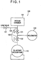
- Fig. 1 is a block diagram schematically showing an arrangement of a vacuum-exhaust device according to the present embodiment.
- a vacuum-exhaust device which is denoted by a numeral 100, is exemplarily applied to an optical interferometer (not shown).
- the vacuum-exhaust device 100 evacuates a vacuum chamber 101 that serves as a vacuum container for forming an interference portion of laser beams in the optical interferometer (i.e., the vacuum-exhaust device 100 exhausts air inside the vacuum chamber 101 to form a vacuum within the vacuum chamber 101).
- the vacuum-exhaust device 100 includes an oil-rotary vacuum pump 110, an exhaust piping 120, a leak pipe 130 as a leak portion, a vacuometer 140 and a controller (not shown).
- the oil-rotary vacuum pump 110 is connected to the vacuum chamber 101 via the exhaust piping 120.
- the oil-rotary vacuum pump 110 is driven to exhaust the air in the vacuum chamber 101 through the exhaust piping 120 so as to evacuate the vacuum chamber 101.
- the oil-rotary vacuum pump 110 may be manually driven by power supplied from, for instance, a power supply (not shown) operated by a power switch, or may be automatically driven in a controllable manner with power supplied from a power supply being controlled by a controller adapted to recognize operations of the switch. Any driving method may be employed.
- the exhaust piping 120 in which a pressure-resistant piping is exemplarily used, is connected to the vacuum chamber 101 at its first end while being connected to the oil-rotary vacuum pump 110 at its second end.
- the exhaust piping 120 is provided with a first on-off valve 121 and a second on-off valve 122.
- the first and second on-off valves 121, 122 form a pair in series.
- the first on-off valve 121 is located adjacent to the vacuum chamber 101 while the second on-off valve 122 is located adjacent to the oil-rotary vacuum pump 110.
- the first on-off valve 121 and the second on-off valve 122 are exemplarily adapted to be electromagnetically opened and closed by a controller (i.e., adapted to be opened and closed by the controller).
- the first and second on-off valves 121, 122 each may be a so-called normal close valve, which is automatically closed when power supplied to the controller is blocked, or the like.
- the leak pipe 130 as the leak portion which may be, for instance, a pressure-resistant pipe as in the exhaust piping 120, is connected to the exhaust piping 120 at its first end to branch from between the vacuum chamber 101 and the second on-off valve 122 (i.e., connected to the exhaust piping 120 in a branched manner).
- a second end of the leak pipe 130 is a free end opened to the atmosphere.
- the leak pipe 130 is provided with a leak valve 131. By opening the leak valve 131, the pressure of the exhaust piping 120 between the vacuum chamber 101 and the second on-off valve 122 is approximated to the atmospheric pressure.
- the vacuometer 140 may be any one of various vacuometers for measuring vacuum degree as long as the vacuometer does not bring harmful effects such as air refraction on the laser beams in the optical interferometer. Examples of such a vacuometer are an ionization vacuum gauge and Pirani gauge.
- the vacuometer 140 is disposed between the first on-off valve 121 and the second on-off valve 122 of the exhaust piping 120 so as to measure vacuum degree thereof.
- the vacuometer 140 which is connected to the controller, outputs data corresponding to the measured vacuum degree to the controller.
- the controller which exemplarily includes a central processing unit (CPU) and the like, controls the first on-off valve 121 and the second on-off valve 122 to be opened and closed in accordance with the vacuum degree measured by the vacuometer 140 in order to evacuate the vacuum chamber 101 or equalize the pressure of the vacuum chamber 101 substantially with the atmospheric pressure.
- CPU central processing unit
- the controller performs a vacuum-exhaust operation, a vacuum-re-exhaust operation and a leak operation. Based on a reference pulse such as internal clock, the controller obtains vacuum-degree data about the vacuum degree measured by the vacuometer 140. Specifically, when vacuum-degree data about the vacuum degree measured and output by the vacuometer 140 is input in the controller, the controller stores the data in a cache memory or the like for suitable computation.
- the controller In the vacuum-exhaust operation, the controller initially recognizes a signal requesting for the vacuum-exhaust operation (i.e., the signal requesting that the vacuum chamber 101 be evacuated) and opens the first on-off valve 121. Then, the vacuometer 140, which has been communicated with the vacuum chamber 101 via the exhaust piping 120 by the opening of the first on-off valve 121, measures the vacuum degree of the vacuum chamber 101, and the controller obtains the vacuum-degree data output by the vacuometer 140 as container vacuum-degree data to store the obtained container vacuum-degree data in a storage such as a random access memory (RAM).
- a signal requesting for the vacuum-exhaust operation i.e., the signal requesting that the vacuum chamber 101 be evacuated
- the vacuometer 140 which has been communicated with the vacuum chamber 101 via the exhaust piping 120 by the opening of the first on-off valve 121, measures the vacuum degree of the vacuum chamber 101, and the controller obtains the vacuum-degree data output by the vacuometer 140 as container vacuum-degree
- the controller closes the first on-off valve 121 while opening the second on-off valve 122, such that the vacuometer 140, which has been communicated with the oil-rotary vacuum pump 110 via the exhaust piping 120 by the opening of the second on-off valve 122, measures the vacuum degree in the vicinity of the oil-rotary vacuum pump 110, and the controller obtains the vacuum-degree data output by the vacuometer 140 as pump vacuum-degree data.
- the signal requesting for the vacuum-exhaust operation which will be described later, may be a signal to the effect that a control signal from a controlling unit has been recognized, a signal to the effect that an actuation of the oil-rotary vacuum pump 110 has been recognized, or the like.
- the controller opens the first on-off valve 121 and the second on-off valve 122 to communicate the chamber 101 with the oil-rotary vacuum pump 110 via the exhaust piping 120, such that the oil-rotary vacuum pump 110 is driven to evacuate the vacuum chamber 101.
- the controller recognizes that the vacuum -degree of the vacuum chamber 101, which is sequentially measured by the vacuometer 140, has reached a predetermined threshold value, the controller closes the second on-off valve 122 and terminates the vacuum-exhaust operation so that the vacuum degree of the vacuum chamber 101 can be monitored through the vacuometer 140 and maintained at the threshold value irrespective of termination of the driving o the oil-rotary vacuum pump 110.
- the controller recognizes a signal requesting for the vacuum-re-exhaust operation (i.e., a signal requesting that the vacuum chamber 101 be evacuated again), the controller recognizes that the first on-off valve 121 is open while the second on-off valve 122 is closed. Then, the vacuometer 140, which is in communication with the vacuum chamber 101 via the exhaust piping 120, measures the vacuum degree of the vacuum chamber, such that the controller stores the measured vacuum degree in the storage.
- the controller switches the opening and closing of the first and second on-off valves 121, 122 such that the first on-off valve 121 is open while the second on-off valve 122 is closed.
- the controller After storing the vacuum degree of the vacuum chamber 101, the controller closes the first on-off valve 121 and opens the second on-off valve 122, so that the vacuometer 140 sequentially measures the vacuum degree in the vicinity of the oil-rotary vacuum pump 110. Then, the controller compares the stored vacuum degree of the vacuum chamber 101 with the sequentially-measured vacuum degree in the vicinity of the oil-rotary vacuum pump 110. When recognizing that the vacuum degree in the vicinity of the oil-rotary vacuum pump 110, which is sequentially measured by the vacuometer 140, becomes equal to or higher than the stored vacuum degree of the vacuum chamber 101, the controller opens the first on-off valve 121.
- both of the first on-off valve 121 and the second on-off valve 122 are open with the first on-off valve 121 being opened, the vacuum chamber 101 and the oil-rotary vacuum pump 110 are communicated with each other, such that the oil-rotary vacuum pump 110 is driven to evacuate the vacuum chamber 101 again.
- the leak valve 131 is opened.
- the leak valve 131 may be manually opened, automatically opened by the controller, or opened by any other suitable method.
- the controller When recognizing that the vacuum degree of the vacuum chamber 101 measured by the vacuometer 140 is substantially equal to the atmospheric pressure, the controller opens the second on-off valve 122. With the second on-off valve 122 being opened, the pressure in the vicinity of the oil-rotary vacuum pump 110 is equalized substantially with the atmospheric pressure.
- the controller controls the oil-rotary vacuum pump 110 to terminate the driving.
- the controller may control the oil-rotary vacuum pump 110 to automatically terminate the driving, control the power supply to be blocked in accordance with a manual termination operation, or control the oil-rotary vacuum pump 110 to terminate the driving by any other suitable method.
- the oil-rotary vacuum pump 110 is stopped after the second on-off valve 122 is opened, thereby reliably preventing contamination by air containing oil or oil vapor.
- the controller is connected with, for instance, a controlling unit such as a personal computer for setting and controlling the entire operation of the optical interferometer.
- a controlling unit such as a personal computer for setting and controlling the entire operation of the optical interferometer.
- an operator i.e., a user of the optical interferometer
- the controlling unit issues various control signals based on various set signals respectively corresponding to the input operations.
- the controller recognizes such control signal(s), the controller controls operations of the entire optical interferometer.
- the vacuum-exhaust operation which is one of the operations of the vacuum-exhaust device 100, will be described below with reference to the attached drawings.
- oil-rotary vacuum pump 110 is exemplarily driven or stopped by manual operations of a user in the present embodiment, the oil-rotary vacuum pump 110 may be automatically driven or stopped by the controller in accordance with, for instance, an input operation for requesting the vacuum-exhaust operation.
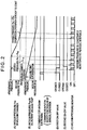
- Fig. 2 is a timing chart showing operations in the vacuum-exhaust operation, in which: (A) is a graph showing vacuum pressure Pvc within the vacuum chamber 101; (B) is a graph showing vacuum pressure Pvp in the oil-rotary vacuum pump 110; (C) is a waveform chart showing a trigger signal; (D) is a waveform showing opening and closing of the first on-off valve 121; (E) is a waveform chart showing opening and closing of the second on-off valve 122; and (F) is a waveform showing timings at which the vacuum degree measured by the vacuometer 140 is read.
- a user of the optical interferometer switches on the oil-rotary vacuum pump 110 for driving while performing an input operation requesting for the vacuum-exhaust operation through the controlling unit so that the vacuum chamber 101 of the optical interferometer is evacuated.
- the controlling unit outputs a control signal related to the request for the vacuum-exhaust operation as shown in Fig. 2(C) .
- the controller having recognized the control signal, controls the first on-off valve 121 to be open for a predetermined time.
- the controller determines whether or not the second on-off valve 122 and the leak valve 131 are closed.
- the controller closes the second on-off valve 122 and the leak valve 131 in advance.
- the leak valve 131 may be automatically switched to be closed by the control of the controller, or may be manually switched to be closed by a user.
- the controller may recognize that the leak valve 131 has been switched to be closed from a report issued when such a switching operation is conducted. In short, any automatic or manual method may be employed.
- the vacuum-exhaust operation is preferably not initiated unless the controller recognizes that the leak valve 131 is switched to be closed. Then, with the first on-off valve 121 being opened, the exhaust piping 120 is communicated with the vacuum chamber 101.
- the controller After controlling the first on-off valve 121 to be switched to be opened, as shown in Fig. 2(F) , the controller starts issuing reference pulse from which a trigger signal for obtaining the data about the vacuum degree measured by the vacuometer 140 is generated.
- the controller obtains the vacuum-degree data about the vacuum degree measured by the vacuometer 140.
- the controller obtains the container vacuum-degree data obtained by the measurement of vacuum degree Pvc (i.e., vacuum pressure of the exhaust piping 120 communicated with the vacuum chamber 101) and stores the obtained container vacuum-degree data in the not-shown storage (see Fig. 2(A) ).
- the controller closes the first on-off valve 121 and subsequently opens the second on-off valve 122 after a predetermined time is elapsed since the closure of the first on-off valve 121 as shown in Fig. 2(E) .
- the exhaust piping 120 is communicated with the oil-rotary vacuum pump 110.
- the controller obtains the vacuum-degree data about the vacuum degree measured by the vacuometer 140.
- the controller obtains the pump vacuum-degree data obtained by the measurement of vacuum degree Pvp (i.e., vacuum pressure of the exhaust piping 120 communicated with the oil-rotary vacuum pump 110) and stores the obtained pump vacuum-degree data in the storage (see Fig. 2(B) ).
- vacuum degree Pvp i.e., vacuum pressure of the exhaust piping 120 communicated with the oil-rotary vacuum pump 110
- the controller compares the container vacuum-degree data stored during the step for storing the vacuum degree of the vacuum container with the pump vacuum-degree data stored during the step for acquiring the vacuum degree of the oil-rotary vacuum pump.
- the controller opens the first on-off valve 121.
- the controller may close the second on-off valve 122 once and subsequently open both the first on-off valve 121 and the second on-off valve 122 in order to check the value of the vacuum degree measured by the vacuometer 140.
- the oil-rotary vacuum pump 110 and the vacuum chamber 101 are communicated with each other via the exhaust piping 120. Then, the oil-rotary vacuum pump 110 is driven to exhaust the air in the vacuum chamber 101 to form a vacuum in the vacuum chamber 101 (i.e., evacuate the vacuum chamber 101).
- the controller obtains the vacuum-degree data from the vacuometer 140 every reference pulse, and determines whether or not the measured vacuum degree has reached a vacuum degree Pm of a predetermined target value (e.g., the controller determines whether or not the measured vacuum degree has reached a value of 0.1 pa).
- the controller recognizes that the vacuum degree of the vacuum chamber 101 has reached the vacuum degree Pm, i.e., the predetermined target threshold value (see Fig. 2(A) and (B) , measurement, observation or the like using the vacuum chamber 101 can be conducted.
- the vacuum degree Pm i.e., the predetermined target threshold value (see Fig. 2(A) and (B)
- the controller may close the second on-off valve 122 to control the oil-rotary vacuum pump 110 to stop the driving, thereby terminating the vacuum-exhaust operation.
- the controller may close the second on-off valve 122 to control the oil-rotary vacuum pump 110 to stop the driving, thereby terminating the vacuum-exhaust operation.
- unnecessary supply of power to the oil-rotary vacuum pump 110 can be prevented, thereby facilitating power saving.
- the second on-off valve 122 is closed after the vacuum degree of the vacuum chamber 101 has reached the targeted vacuum degree Pm in the vacuum-exhaust operation according to the above arrangement, the second on-off valve 122 may not be closed.
- the vacuum-re-exhaust operation which is one of the operations of the vacuum-exhaust device 100, will be described below with reference to the attached drawings.
- the stopped driving of the oil-rotary vacuum pump 110 is resumed so as to evacuate the vacuum chamber 101 again.
- the oil-rotary vacuum pump 110 may be automatically driven or stopped by the controller in accordance with, for instance, an input operation for requesting the vacuum-exhaust operation.
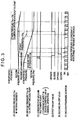
- Fig. 3 is a timing chart showing operations in the vacuum-re-exhaust operation, in which: (A) is a graph showing vacuum pressure Pvc in the vacuum chamber 101; (B) is a graph showing vacuum pressure Pvp in the oil-rotary vacuum pump 110; (C) is a waveform chart showing a trigger signal; (D) is a waveform showing opening and closing of the first on-off valve 121; (E) is a waveform chart showing opening and closing of the second on-off valve 122; and (F) is a waveform showing timings at which the vacuum degree measured by the vacuometer 140 is read.
- a user of the optical interferometer switches on the oil-rotary vacuum pump 110 for driving while performing an input operation requesting for the vacuum-re-exhaust operation through the controlling unit so that the vacuum chamber 101 of the optical interferometer is evacuated again.
- the controlling unit outputs a control signal related to the request for the vacuum-re-exhaust operation as shown in Fig. 3(C) .
- the controller having recognized the control signal, recognizes that the first on-off valve 121 is open while the second on-off valve 122 is closed.
- the controller obtains the vacuum-degree data about the vacuum degree measured by the vacuometer 140 in accordance with the reference pulse (i.e., the controller obtain the container vacuum-degree data provided by the measurement of the vacuum degree Pvc of the exhaust piping 120 communicated with the vacuum chamber 101), and stores the obtained container vacuum-degree data in the storage (not shown) as shown in Fig. 3(A) and (F) .
- the controller switches the opening and closing of the first and second on-off valves 121, 122 such that the first on-off valve 121 is open while the second on-off valve 122 is closed.
- the controller After the vacuum degree of the vacuum chamber 101 is stored, the controller initially closes the first on-off valve 121 (see Fig. 3(D) ) and subsequently opens the second on-off valve 122 (see Fig. 3(E) ). While the second on-off valve 122 is open, the controller obtains the vacuum-degree data about the vacuum degree measured by the vacuometer 140 in accordance with the reference pulse. Specifically, the controller sequentially obtains the pump vacuum-data provided by the measurement of the vacuum degree Pvp of the exhaust piping 120 communicated with the oil-rotary vacuum pump 110. Then, the controller compares the sequentially-obtained vacuum degree Pvp of the oil-rotary vacuum pump 110 with the already-stored vacuum data Pvc of the vacuum chamber 101.
- the controller When recognizing that the vacuum degree Pvp in the vicinity of the oil-rotary vacuum pump 110, which is sequentially measured by the vacuometer 140, becomes equal to or higher than the already-stored vacuum degree Pvc of the vacuum chamber 101, the controller opens the first on-off valve 121.
- the controller may close the second on-off valve 122 once and subsequently open both of the first on-off valve 121 and the second on-off valve 122.
- the leak valve 131 is kept closed so as to more reliably maintain the vacuum.
- operations for stopping the driving of the oil-rotary vacuum pump 110 in order to conduct a calibration is exemplarily described, the same operations are applied when, for instance, the driving of the oil-rotary vacuum pump 110 is stopped after the above-described vacuum-exhaust operation, vacuum-re-exhaust operation or the like in order to reduce a driving cost and the like.
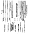
- Fig. 4 is a timing chart showing operations to stop the oil-rotary vacuum pump, in which: (A) is a graph showing vacuum pressure Pvc within the vacuum chamber 101; (B) is a graph showing vacuum pressure Pvp in the oil-rotary vacuum pump 110; (C) is a waveform chart showing a trigger signal; (D) is a waveform showing opening and closing of the first on-off valve 121; (E) is a waveform chart showing opening and closing of the second on-off valve 122; (F) is a waveform showing timings at which vacuum degree measured by the vacuometer 140 is read; and (G) is a waveform showing opening and closing of the leak valve 131.
- a user of the optical interferometer performs an input operation requesting for stopping of the oil-rotary vacuum pump 110 through the controlling unit in order to conduct a calibration of the optical interferometer.
- the controlling unit outputs a control signal related to the request for stopping of the oil-rotary vacuum pump 110 as shown in Fig. 4(C) .
- the controller having recognized the control signal, closes the second on-off valve 122 as shown in Fig. 4(E) .
- the exhaust piping 120 with which the vacuometer 140 is connected, is communicated only with the vacuum chamber 101. While the second on-off valve 122 is closed, the controller obtains the vacuum-degree data about the vacuum degree measured by the vacuometer 140 in accordance with the reference pulse while maintaining the monitoring of the vacuum degree Pvc of the vacuum chamber 101.
- the controller subsequently performs operations necessary for stopping the oil-rotary vacuum pump 110. Specifically, the controller reports to a user by display or audio output that the oil-rotary vacuum pump 110 is allowed to be stopped, or automatically blocks the supply of power to the oil-rotary vacuum pump 110. Then, with the driving of the oil-rotary vacuum pump 110 being stopped, the pressure in the vicinity of the oil-rotary vacuum pump 110 gradually approximates to the atmospheric pressure.
- the oil-rotary vacuum pump 110 while the oil-rotary vacuum pump 110 is driven with the first and second on-off valves 121, 122 being open, the pressure of the vacuum chamber 101 is equalized substantially with the atmospheric pressure.
- the oil-rotary vacuum pump 110 may be automatically driven or stopped by the controller in accordance with, for instance, an input operation for requesting the vacuum-exhaust operation.
- Fig. 5 is a timing chart showing operations of the leak operation, in which: (A) is a graph showing vacuum pressure Pvc within the vacuum chamber 101; (B) is a graph showing vacuum pressure Pvp in the oil-rotary vacuum pump 110; (C) is a waveform chart showing a trigger signal; (D) is a waveform showing opening and closing of the first on-off valve 121; (E) is a waveform chart showing opening and closing of the second on-off valve 122; (F) is a waveform showing timings at which vacuum degree measured by a vacuometer 140 is read; (G) is a waveform showing opening and closing of the leak valve 131; and (H) is a waveform chart showing a trigger signal for opening and closing the leak valve 131.
- the user when a user stops using the optical interferometer and leaves the optical interferometer unused for a relatively long time, in order to approximate the pressure in the vacuum chamber 101 of the optical interferometer to the atmospheric pressure, the user initially performs an input operation for requesting for the leak operation through the controlling unit, such that the controlling unit issues a control signal related to a request for the leak operation as shown in Fig. 5 (C) .
- the controller having recognized the control signal, closes the second on-off valve 122 as shown in Fig. 5(E) . Then, the controller performs operations necessary for opening the leak valve 131 as shown in Fig. 5(G) and (H) .
- the controller reports to the user by display or audio output that the leak valve 131 is allowed to be opened, or automatically switches the leak valve 131 to be opened.
- the vacuum chamber 101 is in communication with the atmosphere, so that the pressure therein approximates to the atmospheric pressure as shown in Fig. 5(A) .
- the controller When subsequently recognizing that the pressure in the vacuum chamber 101 has become substantially the atmospheric pressure based on the container vacuum-degree data measured by the vacuometer 140, the controller opens the second on-off valve 122 while stopping monitoring the vacuum degree by stopping the issue of the reference pulse as shown in Fig. 5(E) .
- the oil-rotary vacuum pump 110 is communicated with the atmosphere by this operation, the oil-rotary vacuum pump 110 maintains a reduced pressure that is approximate to that of the atmospheric pressure as shown in Fig. 5(B) because the oil-rotary vacuum pump 110 is being driven to vacuum suction.
- the controller subsequently performs operations necessary for stopping the oil-rotary vacuum pump 110.
- the controller reports to a user by display or audio output that the oil-rotary vacuum pump 110 is allowed to be stopped, or automatically blocks the supply of power to the oil-rotary vacuum pump 110. Then, with the driving of the oil-rotary vacuum pump 110 being stopped, the pressure in the vicinity of the oil-rotary vacuum pump 110 gradually approximates to the atmospheric pressure. Through the above operations, the pressure in the vacuum chamber 101 of the optical interferometer is equalized substantially with the atmospheric pressure.
- the pair of first on-off valve 121 and the second on-off valve 122 for evacuating the vacuum chamber 101 are provided in series between the vacuum chamber 101 and the oil-rotary vacuum pump 110, and the vacuometer 140 for measuring the vacuum degree is provided between the first on-off valve 121 and the second on-off valve 122.
- the vacuum degree Pvc of the vacuum chamber 101 can be measured.
- the second on-off valve 122 adjacent to the oil-rotary vacuum pump 110 By opening the second on-off valve 122 adjacent to the oil-rotary vacuum pump 110, the vacuum degree Pvp in the vicinity of the oil-rotary vacuum pump 110 can be measured.
- the vacuum chamber 101 can be evacuated by the driven oil-rotary vacuum pump 110 while the vacuum degree can be measured.
- the vacuum degree can be suitably measured with the single vacuometer 140.
- a configuration of the vacuum-exhaust device can be simplified, thereby easily enhancing manufacturability and reducing cost for the vacuum-exhaust device.
- the controller controls the opening and closing of the pair of first and second on-off valves 121, 122 based on the vacuum degree measured by the vacuometer 140.
- the controller controls the vacuum-exhaust operation. Specifically, the controller initially opens the first on-off valve 121 adjacent to the vacuum chamber 101 to store the vacuum degree of the vacuum chamber 101 measured by the vacuometer 140, and subsequently closes the first on-off valve 121. Then, the controller opens the second on-off valve 122 adjacent to the oil-rotary vacuum pump 110 to obtain the vacuum degree in the vicinity of the oil-rotary vacuum pump 110 measured by the vacuometer 140. Following the above, the controller compares the stored container vacuum degree Pvc in the vacuum chamber 101 with the pump vacuum degree Pvp in the vicinity of the oil-rotary vacuum pump 110 measured by the vacuometer 140.
- the controller When recognizing that the vacuum degree Pvp in the vicinity of the oil-rotary vacuum pump 110 has become larger than the stored vacuum degree Pvc in the vacuum container 101, the controller opens both of the first on-off valve 121 and the second on-off valve 122, so that the vacuum chamber 101 is evacuated by the driving of the oil-rotary vacuum pump 110.
- the vacuum chamber 101 can be suitably evacuated with the single vacuometer 140 used.
- the controller obtains the vacuum degree in the vicinity of the oil-rotary vacuum pump 110 and subsequently opens both of the first on-off valve 121 and the second on-off valve 122 to evacuate the vacuum chamber 101. Then, when recognizing that the vacuum degree Pvc of the vacuum chamber 101 measured by the vacuometer 140 is equal to the predetermined vacuum degree Pm, the controller closes the second on-off valve 122.
- the controller opens the first on-off valve 121 while closing the second on-off valve 122, so that the oil-rotary vacuum pump 110 is controlled to terminate the driving.
- the controller controls the oil-rotary vacuum pump 110 to automatically terminate the driving, controls the power supply to be blocked in accordance with a manual termination operation, or reports to a user so that the user can manually stop the oil-rotary vacuum pump 110.
- the controller controls the vacuum-re-exhaust operation. Specifically, after storing the vacuum degree Pvc of the vacuum chamber 101 measured by the vacuometer 140 with the first on-off valve 121 being open while the second on-off valve 122 being closed, the controller closes the first on-off valve 121 and subsequently opens the second on-off valve 122, so that the vacuometer 140 sequentially measures the vacuum degree Pvp in the vicinity of the oil-rotary vacuum pump 110.
- the controller compares the stored vacuum degree Pvc of the vacuum chamber 101 with the sequentially measured vacuum degree Pvp in the vicinity of the oil-rotary vacuum pump 110.
- the controller opens the first on-off valve 121 to open both of the first and second on-off valves 121, 122, so that the vacuum chamber 101 can be evacuated again by the driving of the oil-rotary vacuum pump 110.
- the vacuum chamber 101 can be suitably evacuated with the single vacuometer 140 used.
- the leak pipe 130 having the leak valve 131 for equalizing the pressure of the exhaust piping 120 between the vacuum chamber 101 and the first on-off valve 121 substantially with the atmospheric pressure when opened is provided in a branched manner between the vacuum chamber 101 and the first on-off valve 121 adjacent to the vacuum chamber 101.
- the leak valve is opened after closing of the second on-off valve 122 and opening of the first on-off valve 121, so that the pressure of the exhaust piping 120 between the vacuum chamber 101 and the second on-off valve 122 is equalized substantially with the atmospheric pressure.
- the second on-off valve 122 is subsequently opened, air in the vacuum chamber 101, in which the pressure has been equalized substantially with the atmospheric pressure, flows into the oil-rotary vacuum pump 110. Accordingly, the oil-rotary vacuum pump 110 is required to be stopped only after the air flows into the oil-rotary vacuum pump 110 from the vacuum chamber 101.
- the pressure of the vacuum chamber 101 can be favorably equalized substantially with the atmospheric pressure with a simplified arrangement in a facilitated manner.
- the leak valve 131 is opened after the second on-off valve 122 is closed.
- the leak valve 131 may be manually opened, automatically opened by the controller, or opened by any other suitable method.
- the controller opens the second on-off valve 122, so that the pressure in the vicinity of the oil-rotary vacuum pump 110 is equalized substantially with the atmospheric pressure.
- the controller controls the oil-rotary vacuum pump 110 to terminate the driving.
- the controller may control the oil-rotary vacuum pump 110 to automatically terminate the driving, controls the power supply to be blocked in accordance with a manual termination operation, or report to a user so that the user can manually stop the oil-rotary vacuum pump 110.
- the pressure of the vacuum chamber 101 when the pressure of the vacuum chamber 101 is equalized substantially with the atmospheric pressure, the pressure of the vacuum chamber 101 can be suitably equalized substantially with the atmospheric pressure with the single vacuometer 140 used while oil, oil vapor and the like from the oil-rotary vacuum pump 110 are prevented from flowing into the vacuum chamber 101.
- the above-described aspect of the present invention merely forms one aspect of the present invention.
- the present invention is not limited to the above-described embodiment but may include any modification or improvement made within a scope where an object and an effect of the present invention can be achieved.
- specific structure, shape and the like in implementing the present invention may be altered to other structure, shape and the like as long as an object and an effect of the present invention can be achieved.
- the vacuum-exhaust device according to the present invention has been exemplified by the arrangement for evacuating the vacuum chamber 101 (the vacuum container) of the optical interferometer in the above-described embodiment, the present invention may be applied to any other arrangement for evacuating various vacuum containers used in devices such as an electronic microscope.
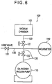
- the leak pipe 130 having the leak valve 131 is provided to the exhaust piping 120 between the vacuum chamber 101 and the first on-off valve 121 in a branched manner in the above embodiment, the leak pipe 130 may be provided between the first on-off valve 121 and the second on-off valve 122 in a branched manner as exemplarily shown in Fig. 6 ..
- the pressure of the vacuum chamber 101 is initially equalized substantially with the atmospheric pressure by opening the first on-off valve 121, and the pressure in the vicinity of the oil-rotary vacuum pump 110 is subsequently equalized substantially with the atmospheric pressure by opening the second on-off valve 122, so that the oil-rotary vacuum pump 110 is stopped.
- the oil and the like from the oil-rotary vacuum pump 110 is prevented from flowing into the vacuum chamber 101.
Landscapes
- Engineering & Computer Science (AREA)
- Mechanical Engineering (AREA)
- General Engineering & Computer Science (AREA)
- Compressors, Vaccum Pumps And Other Relevant Systems (AREA)
- Physical Vapour Deposition (AREA)
- Applications Or Details Of Rotary Compressors (AREA)
Claims (10)
- Dispositif d'extraction sous vide (100) relié à un réservoir sous vide (101) et conçu pour vider le réservoir sous vide (101), le dispositif d'extraction sous vide (100) comprenant :une pompe à vide tournante à l'huile (110) reliée au réservoir sous vide (101) et conçue pour vider le réservoir sous vide (101),une paire de vannes tout ou rien (121, 122) disposées en série entre le réservoir sous vide (101) et la pompe à vide tournante à l'huile (110),un vacuomètre (140) positionné entre la paire de vannes tout ou rien (121, 122) et conçu pour mesurer le degré de vide, etun contrôleur commandant la paire de vannes tout ou rien (121, 122) pour qu'elles soient ouvertes ou fermées sur la base du degré de vide mesuré par le vacuomètre (140),caractérisé en ce quele contrôleur est configuré pour commander une opération d'extraction sous vide de sorte que :une première vanne tout ou rien (121), disposée adjacente au réservoir sous vide (101), est ouverte pendant une durée prédéterminée, lorsque la pompe à vide tournante à l'huile (110) est entraînée, de façon à stocker des données de degré de vide de réservoir concernant le degré de vide du réservoir sous vide (101) mesuré par le vacuomètre (140),la première vanne tout ou rien (121) est fermée et une seconde vanne tout ou rien (122) disposée adjacente à la pompe à vide tournante à l'huile (110) est ensuite ouverte de façon à obtenir des données de degré de vide de pompe concernant le degré de vide au voisinage de la pompe à vide tournante à l'huile (110) mesuré par le vacuomètre (140), etla paire de vannes tout ou rien (121, 122) est ouverte lorsque le contrôleur reconnaît que le degré de vide au voisinage de la pompe à vide tournante à l'huile (110) est devenu plus grand que le degré de vide de réservoir stocké du réservoir sous vide (101) en comparant les données de degré de vide de réservoir stockées aux données de vide de pompe concernant le degré de vide au voisinage de la pompe à vide tournante à l'huile (110) mesuré par le vacuomètre (140) après que le degré de vide au voisinage de la pompe à vide tournante à l'huile (110) a été obtenu.
- Dispositif d'évacuation sous vide (100) selon la revendication 1, dans lequel le contrôleur commande la seconde vanne tout ou rien (122) afin de l'ouvrir pendant une durée prédéterminée lors de la récupération des données de vide de pompe concernant le degré de vide au voisinage de la pompe à vide tournante à l'huile (110) mesuré par le vacuomètre (140).
- Dispositif d'évacuation sous vide (100) selon la revendication 1 ou la revendication 2, dans lequel
le contrôleur ouvre la paire de vannes tout ou rien (121, 122) après avoir récupéré les données de degré de vide concernant le degré de vide au voisinage de la pompe à vide tournante à l'huile (110), et
le contrôleur ferme la seconde vanne tout ou rien (122) lorsqu'il reconnaît que le degré de vide du réservoir sous vide (101) mesuré par le vacuomètre (140) a atteint un degré de vide prédéterminé. - Dispositif d'évacuation sous vide (100) selon la revendication 3, dans lequel le contrôleur commande la seconde vanne tout ou rien (122) afin de la fermer après que le degré de vide du réservoir sous vide (101) a atteint le degré de vide prédéterminé, et il commande ensuite la pompe à vide tournante à l'huile (110) afin de stopper l'entraînement.
- Dispositif d'évacuation sous vide (100) selon la revendication 3 ou la revendication 4, dans lequel le contrôleur commande une opération de ré évacuation sous vide de sorte à ce que :les données de degré de vide de réservoir concernant le degré de vide du réservoir sous vide (101) sont stockées lorsque la pompe à vide tournante à l'huile (110) reprend l'entraînement en raison d'une diminution du degré de vide du réservoir (101), le degré de vide du réservoir sous vide (101) étant mesuré par le vacuomètre (140) pendant que la première vanne tout ou rien (121) est ouverte alors que la seconde vanne tout ou rien (122) est fermée,la première vanne tout ou rien (121) est fermée après que les données de degré de vide de réservoir ont été stockées et la seconde vanne tout ou rien (122) est ensuite ouverte de façon à comparer les données de degré de vide de réservoir stockées aux données de degré de vide de pompe concernant le degré de vide au voisinage de la pompe à vide tournante à l'huile (110) mesuré séquentiellement par le vacuomètre (140), etla première vanne tout ou rien (121) est ouverte lorsque le contrôleur reconnaît que le degré de vide au voisinage de la pompe à vide tournante à l'huile (110) contenu dans les données de degré de vide de pompe est devenu supérieur ou égal au degré de vide stocké du réservoir sous vide (101).
- Dispositif d'évacuation sous vide (100) selon l'une quelconque des revendications 1 à 5, comprenant en outre un organe de fuite (130) disposé dans une dérivation entre le réservoir sous vide (101) et la première vanne tout ou rien (121) adjacente au réservoir sous vide (101), l'organe de fuite (130) comprenant une vanne de fuite (131) conçue pour pratiquement égaliser la pression d'une zone comprise entre le réservoir sous vide (101) et la première vanne tout ou rien (121) avec la pression atmosphérique lorsqu'elle est ouverte.
- Dispositif d'évacuation sous vide (100) selon la revendication 6, dans lequel le contrôleur commande une opération de fuite de sorte à ce que :la vanne de fuite (131) est commandée pour s'ouvrir après que la seconde vanne tout ou rien (122) adjacente à la pompe à vide tournante à l'huile (110) a été fermée,la pompe à vide tournante à l'huile (110) est commandée pour arrêter l'entraînement lorsque le contrôleur reconnaît que le degré de vide du réservoir sous vide (101) mesuré par le vacuomètre (140) est devenu pratiquement égal à la pression atmosphérique, etla seconde vanne tout ou rien (122) est ouverte.
- Dispositif d'évacuation sous vide (100) selon l'une quelconque des revendications 1 à 5, comprenant en outre un organe de fuite (130) disposés dans une dérivation entre la paire de vannes tout ou rien (121, 122), l'organe de fuite (130) comprenant une vanne de fuite (131) conçue pour égaliser pratiquement la pression d'une zone entre la paire de vannes tout ou rien (121, 122) avec la pression atmosphérique lorsqu'elle est ouverte.
- Dispositif d'évacuation sous vide (100) selon la revendication 8, dans lequel le contrôleur commande une opération de fuite de sorte à ce que :la vanne de fuite (131) soit commandée pour être ouverte et la première vanne tout ou rien (121) adjacente au réservoir (101) soit commandée pour être ouverte après que la seconde vanne tout ou rien (122) adjacente à la pompe à vide tournante à l'huile (110) a été fermée, etla seconde vanne tout ou rien (122) soit commandée pour être ouverte lorsque le contrôleur reconnaît que le degré de vide du réservoir sous vide (101) mesuré par le vacuomètre (140) est devenu pratiquement égal à la pression atmosphérique.
- Procédé d'évacuation sous vide permettant de vider un réservoir sous vide (101), le procédé comprenant :l'utilisation d'une pompe à vide tournante à l'huile (110) conçue pour vider le réservoir (101) par l'intermédiaire d'une paire de vannes tout ou rien (121, 122) disposées en série, ainsi qu'un vacuomètre (140) positionné entre la paire de vannes tout ou rien (121, 122) et conçu pour mesurer un degré de vide,l'ouverture d'une première vanne tout ou rien (121) disposée adjacente au réservoir sous vide (101) pendant une durée prédéterminée lorsque la pompe à vide tournante à l'huile (110) est entraînée, et le stockage de données de degré de vide de réservoir concernant le degré de vide du réservoir sous vide (101) mesuré par le vacuomètre (140),la fermeture de la première vanne tout ou rien (121) pour ensuite ouvrir une seconde vanne tout ou rien (122) disposée adjacente à la pompe à vide tournante à l'huile (110) après le stockage de degré de vide du réservoir sous vide (101), et la récupération de données de degré de vide de pompe concernant le degré de vide au voisinage de la pompe à vide tournante à l'huile (110) mesuré par le vacuomètre (140), etla comparaison des données de degré de vide de réservoir stockées aux données de degré de vide de pompe au voisinage de la pompe à vide tournante à l'huile et, lorsque le degré de vide de pompe au voisinage de la pompe à vide tournante à l'huile est supérieur au degré de vide de réservoir stocké du réservoir sous vide,la vidange du réservoir sous vide (101) par la pompe à vide tournante à l'huile (110) entraînée, la paire de vannes tout ou rien (121, 122) étant ouverte après que le degré de vide au voisinage de la pompe à vide tournante à l'huile (110) a été obtenu.
Applications Claiming Priority (2)
| Application Number | Priority Date | Filing Date | Title |
|---|---|---|---|
| JP2007167639 | 2007-06-26 | ||
| JP2008162248A JP5216433B2 (ja) | 2007-06-26 | 2008-06-20 | 真空排気装置および真空排気方法 |
Publications (3)
| Publication Number | Publication Date |
|---|---|
| EP2009287A2 EP2009287A2 (fr) | 2008-12-31 |
| EP2009287A3 EP2009287A3 (fr) | 2016-07-20 |
| EP2009287B1 true EP2009287B1 (fr) | 2017-11-29 |
Family
ID=39817150
Family Applications (1)
| Application Number | Title | Priority Date | Filing Date |
|---|---|---|---|
| EP08011531.4A Ceased EP2009287B1 (fr) | 2007-06-26 | 2008-06-25 | Dispositif et procédé d'échappement sous vide |
Country Status (1)
| Country | Link |
|---|---|
| EP (1) | EP2009287B1 (fr) |
Families Citing this family (5)
| Publication number | Priority date | Publication date | Assignee | Title |
|---|---|---|---|---|
| CN109839887A (zh) * | 2017-11-28 | 2019-06-04 | 南京润邦金属复合材料有限公司 | 一种真空叠轧金属复合板板坯真空制备自动检测控制装置及方法 |
| CN116892495B (zh) * | 2023-07-05 | 2026-04-21 | 北京卫星环境工程研究所 | 一种用于氢原子钟地面测试的外真空获得和磁屏蔽设备 |
| CN117846940A (zh) * | 2024-01-18 | 2024-04-09 | 江苏省精创电气股份有限公司 | 一种真空泵自动控制方法及系统 |
| CN120024862A (zh) * | 2024-11-08 | 2025-05-23 | 上海联影医疗科技股份有限公司 | 便携式真空注油工装及真空注油方法 |
| CN119223519B (zh) * | 2024-11-28 | 2025-02-18 | 福建建壹真空科技有限公司 | 一种静态膨胀法真空标准装置 |
Family Cites Families (4)
| Publication number | Priority date | Publication date | Assignee | Title |
|---|---|---|---|---|
| JP3275098B2 (ja) | 1991-08-09 | 2002-04-15 | 日本酸素株式会社 | 真空排気装置及びその起動方法 |
| JPH07197884A (ja) * | 1993-12-28 | 1995-08-01 | Ulvac Japan Ltd | 真空排気管路における油蒸気逆流防止装置 |
| JP2003157786A (ja) | 2001-11-20 | 2003-05-30 | Hitachi High-Technologies Corp | 走査電子顕微鏡 |
| JP2006322405A (ja) * | 2005-05-19 | 2006-11-30 | Denso Corp | 真空排気システム |
-
2008
- 2008-06-25 EP EP08011531.4A patent/EP2009287B1/fr not_active Ceased
Non-Patent Citations (1)
| Title |
|---|
| None * |
Also Published As
| Publication number | Publication date |
|---|---|
| EP2009287A2 (fr) | 2008-12-31 |
| EP2009287A3 (fr) | 2016-07-20 |
Similar Documents
| Publication | Publication Date | Title |
|---|---|---|
| EP2009287B1 (fr) | Dispositif et procédé d'échappement sous vide | |
| JP5292261B2 (ja) | リークディテクタ | |
| US20090165470A1 (en) | Cryopump, cryopump unit, vacuum processing apparatus including cryopump unit, and cryopump regeneration method | |
| TWI484582B (zh) | An action monitoring system for a processing device | |
| KR20090025823A (ko) | 이동없이 가능한 진공게이지의 교정/시험 장치 및 그 방법 | |
| US10982662B2 (en) | Pumping system | |
| KR940006184A (ko) | 감압처리장치 및 감압처리방법 | |
| JP2018021546A (ja) | 真空発生器を含む真空システムの制御 | |
| JP2019035608A (ja) | リーク検査装置およびリーク検査装置における検査ガス回収方法 | |
| KR100745372B1 (ko) | 반도체 제조설비의 개스플로우량 감시장치 및 그 방법 | |
| CN115148567A (zh) | 扫描电镜的真空系统及其控制方法 | |
| JP5216433B2 (ja) | 真空排気装置および真空排気方法 | |
| JP3776467B2 (ja) | 排気系ネットワーク | |
| JPH09126125A (ja) | クライオポンプの再生方法及びその再生装置 | |
| JP5008086B2 (ja) | 調圧機能付高速ガス切替装置 | |
| JP2826479B2 (ja) | ガス供給装置及びその操作方法 | |
| TW200719395A (en) | Vacuum processing system and method of operating same | |
| JP2002025918A (ja) | 半導体製造装置 | |
| JP2007095728A (ja) | デバイス製造装置及びリークチェック方法 | |
| US20250201545A1 (en) | Vacuum system for a mass spectrometer | |
| KR100196901B1 (ko) | 진공 챔버의 압력 측정방법 | |
| KR101478633B1 (ko) | 가스배관의 수분 검출장치 및 방법 | |
| JPH03157585A (ja) | 真空装置およびその使用方法 | |
| KR20060085716A (ko) | 반도체 설비의 이중 실링을 위한 슬롯 밸브 장치 | |
| US20140349826A1 (en) | Centrifuge |
Legal Events
| Date | Code | Title | Description |
|---|---|---|---|
| PUAI | Public reference made under article 153(3) epc to a published international application that has entered the european phase |
Free format text: ORIGINAL CODE: 0009012 |
|
| AK | Designated contracting states |
Kind code of ref document: A2 Designated state(s): AT BE BG CH CY CZ DE DK EE ES FI FR GB GR HR HU IE IS IT LI LT LU LV MC MT NL NO PL PT RO SE SI SK TR |
|
| AX | Request for extension of the european patent |
Extension state: AL BA MK RS |
|
| PUAL | Search report despatched |
Free format text: ORIGINAL CODE: 0009013 |
|
| AK | Designated contracting states |
Kind code of ref document: A3 Designated state(s): AT BE BG CH CY CZ DE DK EE ES FI FR GB GR HR HU IE IS IT LI LT LU LV MC MT NL NO PL PT RO SE SI SK TR |
|
| AX | Request for extension of the european patent |
Extension state: AL BA MK RS |
|
| RIC1 | Information provided on ipc code assigned before grant |
Ipc: F04B 37/16 20060101ALI20160613BHEP Ipc: F04B 49/06 20060101ALI20160613BHEP Ipc: F04D 19/04 20060101AFI20160613BHEP Ipc: F04C 25/02 20060101ALI20160613BHEP |
|
| 17P | Request for examination filed |
Effective date: 20161114 |
|
| RBV | Designated contracting states (corrected) |
Designated state(s): AT BE BG CH CY CZ DE DK EE ES FI FR GB GR HR HU IE IS IT LI LT LU LV MC MT NL NO PL PT RO SE SI SK TR |
|
| RBV | Designated contracting states (corrected) |
Designated state(s): AT BE BG CH CY CZ DE DK EE ES FI FR GB GR HR HU IE IS IT LI LT LU LV MC MT NL NO PL PT RO SE SI SK TR |
|
| AKX | Designation fees paid |
Designated state(s): DE FR GB |
|
| AXX | Extension fees paid |
Extension state: MK Extension state: AL Extension state: RS Extension state: BA |
|
| RIC1 | Information provided on ipc code assigned before grant |
Ipc: F04C 25/02 20060101ALI20170509BHEP Ipc: F04B 37/16 20060101ALI20170509BHEP Ipc: F04B 49/06 20060101ALI20170509BHEP Ipc: F04D 19/04 20060101AFI20170509BHEP |
|
| GRAP | Despatch of communication of intention to grant a patent |
Free format text: ORIGINAL CODE: EPIDOSNIGR1 |
|
| INTG | Intention to grant announced |
Effective date: 20170609 |
|
| INTG | Intention to grant announced |
Effective date: 20170619 |
|
| GRAS | Grant fee paid |
Free format text: ORIGINAL CODE: EPIDOSNIGR3 |
|
| GRAA | (expected) grant |
Free format text: ORIGINAL CODE: 0009210 |
|
| AK | Designated contracting states |
Kind code of ref document: B1 Designated state(s): DE FR GB |
|
| REG | Reference to a national code |
Ref country code: GB Ref legal event code: FG4D |
|
| REG | Reference to a national code |
Ref country code: DE Ref legal event code: R096 Ref document number: 602008053134 Country of ref document: DE |
|
| REG | Reference to a national code |
Ref country code: FR Ref legal event code: PLFP Year of fee payment: 11 |
|
| REG | Reference to a national code |
Ref country code: DE Ref legal event code: R097 Ref document number: 602008053134 Country of ref document: DE |
|
| PLBE | No opposition filed within time limit |
Free format text: ORIGINAL CODE: 0009261 |
|
| STAA | Information on the status of an ep patent application or granted ep patent |
Free format text: STATUS: NO OPPOSITION FILED WITHIN TIME LIMIT |
|
| 26N | No opposition filed |
Effective date: 20180830 |
|
| PGFP | Annual fee paid to national office [announced via postgrant information from national office to epo] |
Ref country code: FR Payment date: 20210622 Year of fee payment: 14 Ref country code: DE Payment date: 20210618 Year of fee payment: 14 |
|
| PGFP | Annual fee paid to national office [announced via postgrant information from national office to epo] |
Ref country code: GB Payment date: 20210625 Year of fee payment: 14 |
|
| REG | Reference to a national code |
Ref country code: DE Ref legal event code: R119 Ref document number: 602008053134 Country of ref document: DE |
|
| GBPC | Gb: european patent ceased through non-payment of renewal fee |
Effective date: 20220625 |
|
| PG25 | Lapsed in a contracting state [announced via postgrant information from national office to epo] |
Ref country code: FR Free format text: LAPSE BECAUSE OF NON-PAYMENT OF DUE FEES Effective date: 20220630 |
|
| PG25 | Lapsed in a contracting state [announced via postgrant information from national office to epo] |
Ref country code: GB Free format text: LAPSE BECAUSE OF NON-PAYMENT OF DUE FEES Effective date: 20220625 Ref country code: DE Free format text: LAPSE BECAUSE OF NON-PAYMENT OF DUE FEES Effective date: 20230103 |