EP2009337B1 - Agencement et procédé de fixation de conduites - Google Patents
Agencement et procédé de fixation de conduites Download PDFInfo
- Publication number
- EP2009337B1 EP2009337B1 EP08011638.7A EP08011638A EP2009337B1 EP 2009337 B1 EP2009337 B1 EP 2009337B1 EP 08011638 A EP08011638 A EP 08011638A EP 2009337 B1 EP2009337 B1 EP 2009337B1
- Authority
- EP
- European Patent Office
- Prior art keywords
- holding device
- pipe
- shaped
- corrugated
- assembly
- Prior art date
- Legal status (The legal status is an assumption and is not a legal conclusion. Google has not performed a legal analysis and makes no representation as to the accuracy of the status listed.)
- Not-in-force
Links
- 238000000034 method Methods 0.000 title claims description 20
- 125000006850 spacer group Chemical group 0.000 claims description 15
- 238000005452 bending Methods 0.000 claims description 2
- 238000004804 winding Methods 0.000 description 10
- 239000000463 material Substances 0.000 description 8
- 238000004519 manufacturing process Methods 0.000 description 4
- 238000006073 displacement reaction Methods 0.000 description 3
- 238000009434 installation Methods 0.000 description 3
- 229920001169 thermoplastic Polymers 0.000 description 3
- 239000004416 thermosoftening plastic Substances 0.000 description 3
- 238000010276 construction Methods 0.000 description 2
- 238000010438 heat treatment Methods 0.000 description 2
- 230000015572 biosynthetic process Effects 0.000 description 1
- 238000009954 braiding Methods 0.000 description 1
- 238000005253 cladding Methods 0.000 description 1
- 238000009826 distribution Methods 0.000 description 1
- 230000005489 elastic deformation Effects 0.000 description 1
- 238000005516 engineering process Methods 0.000 description 1
- 229920002457 flexible plastic Polymers 0.000 description 1
- 238000005755 formation reaction Methods 0.000 description 1
- 239000002184 metal Substances 0.000 description 1
- 239000000546 pharmaceutical excipient Substances 0.000 description 1
- 239000004033 plastic Substances 0.000 description 1
- 229920003023 plastic Polymers 0.000 description 1
- 238000002360 preparation method Methods 0.000 description 1
- 239000012815 thermoplastic material Substances 0.000 description 1
Images

Classifications
-
- F—MECHANICAL ENGINEERING; LIGHTING; HEATING; WEAPONS; BLASTING
- F16—ENGINEERING ELEMENTS AND UNITS; GENERAL MEASURES FOR PRODUCING AND MAINTAINING EFFECTIVE FUNCTIONING OF MACHINES OR INSTALLATIONS; THERMAL INSULATION IN GENERAL
- F16L—PIPES; JOINTS OR FITTINGS FOR PIPES; SUPPORTS FOR PIPES, CABLES OR PROTECTIVE TUBING; MEANS FOR THERMAL INSULATION IN GENERAL
- F16L3/00—Supports for pipes, cables or protective tubing, e.g. hangers, holders, clamps, cleats, clips, brackets
- F16L3/08—Supports for pipes, cables or protective tubing, e.g. hangers, holders, clamps, cleats, clips, brackets substantially surrounding the pipe, cable or protective tubing
- F16L3/12—Supports for pipes, cables or protective tubing, e.g. hangers, holders, clamps, cleats, clips, brackets substantially surrounding the pipe, cable or protective tubing comprising a member substantially surrounding the pipe, cable or protective tubing
- F16L3/13—Supports for pipes, cables or protective tubing, e.g. hangers, holders, clamps, cleats, clips, brackets substantially surrounding the pipe, cable or protective tubing comprising a member substantially surrounding the pipe, cable or protective tubing and engaging it by snap action
-
- F—MECHANICAL ENGINEERING; LIGHTING; HEATING; WEAPONS; BLASTING
- F16—ENGINEERING ELEMENTS AND UNITS; GENERAL MEASURES FOR PRODUCING AND MAINTAINING EFFECTIVE FUNCTIONING OF MACHINES OR INSTALLATIONS; THERMAL INSULATION IN GENERAL
- F16L—PIPES; JOINTS OR FITTINGS FOR PIPES; SUPPORTS FOR PIPES, CABLES OR PROTECTIVE TUBING; MEANS FOR THERMAL INSULATION IN GENERAL
- F16L3/00—Supports for pipes, cables or protective tubing, e.g. hangers, holders, clamps, cleats, clips, brackets
- F16L3/08—Supports for pipes, cables or protective tubing, e.g. hangers, holders, clamps, cleats, clips, brackets substantially surrounding the pipe, cable or protective tubing
- F16L3/12—Supports for pipes, cables or protective tubing, e.g. hangers, holders, clamps, cleats, clips, brackets substantially surrounding the pipe, cable or protective tubing comprising a member substantially surrounding the pipe, cable or protective tubing
- F16L3/133—Supports for pipes, cables or protective tubing, e.g. hangers, holders, clamps, cleats, clips, brackets substantially surrounding the pipe, cable or protective tubing comprising a member substantially surrounding the pipe, cable or protective tubing and hanging from a pendant
-
- F—MECHANICAL ENGINEERING; LIGHTING; HEATING; WEAPONS; BLASTING
- F16—ENGINEERING ELEMENTS AND UNITS; GENERAL MEASURES FOR PRODUCING AND MAINTAINING EFFECTIVE FUNCTIONING OF MACHINES OR INSTALLATIONS; THERMAL INSULATION IN GENERAL
- F16L—PIPES; JOINTS OR FITTINGS FOR PIPES; SUPPORTS FOR PIPES, CABLES OR PROTECTIVE TUBING; MEANS FOR THERMAL INSULATION IN GENERAL
- F16L3/00—Supports for pipes, cables or protective tubing, e.g. hangers, holders, clamps, cleats, clips, brackets
- F16L3/22—Supports for pipes, cables or protective tubing, e.g. hangers, holders, clamps, cleats, clips, brackets specially adapted for supporting a number of parallel pipes at intervals
- F16L3/223—Supports for pipes, cables or protective tubing, e.g. hangers, holders, clamps, cleats, clips, brackets specially adapted for supporting a number of parallel pipes at intervals each support having one transverse base for supporting the pipes
-
- F—MECHANICAL ENGINEERING; LIGHTING; HEATING; WEAPONS; BLASTING
- F28—HEAT EXCHANGE IN GENERAL
- F28F—DETAILS OF HEAT-EXCHANGE AND HEAT-TRANSFER APPARATUS, OF GENERAL APPLICATION
- F28F9/00—Casings; Header boxes; Auxiliary supports for elements; Auxiliary members within casings
- F28F9/007—Auxiliary supports for elements
- F28F9/013—Auxiliary supports for elements for tubes or tube-assemblies
-
- F—MECHANICAL ENGINEERING; LIGHTING; HEATING; WEAPONS; BLASTING
- F28—HEAT EXCHANGE IN GENERAL
- F28F—DETAILS OF HEAT-EXCHANGE AND HEAT-TRANSFER APPARATUS, OF GENERAL APPLICATION
- F28F9/00—Casings; Header boxes; Auxiliary supports for elements; Auxiliary members within casings
- F28F9/007—Auxiliary supports for elements
- F28F9/013—Auxiliary supports for elements for tubes or tube-assemblies
- F28F9/0137—Auxiliary supports for elements for tubes or tube-assemblies formed by wires, e.g. helically coiled
-
- F—MECHANICAL ENGINEERING; LIGHTING; HEATING; WEAPONS; BLASTING
- F28—HEAT EXCHANGE IN GENERAL
- F28D—HEAT-EXCHANGE APPARATUS, NOT PROVIDED FOR IN ANOTHER SUBCLASS, IN WHICH THE HEAT-EXCHANGE MEDIA DO NOT COME INTO DIRECT CONTACT
- F28D7/00—Heat-exchange apparatus having stationary tubular conduit assemblies for both heat-exchange media, the media being in contact with different sides of a conduit wall
- F28D7/02—Heat-exchange apparatus having stationary tubular conduit assemblies for both heat-exchange media, the media being in contact with different sides of a conduit wall the conduits being helically coiled
-
- F—MECHANICAL ENGINEERING; LIGHTING; HEATING; WEAPONS; BLASTING
- F28—HEAT EXCHANGE IN GENERAL
- F28F—DETAILS OF HEAT-EXCHANGE AND HEAT-TRANSFER APPARATUS, OF GENERAL APPLICATION
- F28F1/00—Tubular elements; Assemblies of tubular elements
- F28F1/08—Tubular elements crimped or corrugated in longitudinal section
Definitions
- the invention relates to an arrangement for fixing lines, which is largely universally applicable. It also relates to a method for fixing leads by means of the arrangement and the use of the arrangement.
- cables are to be fastened with pipe clamps or bandages, a suitable fastening location (masonry, wooden beams, construction parts and the like) is always required. If mounting locations are not available at the necessary distance, cables must be designed to be more stable than technically necessary.
- thermoplastic spacers for a finite number of parallel and spaced mutually extending flexible plastic pipes, which consist of thermoplastic material and should be brought into their shape under the action of heat.
- thermoplastic spacers only one Therefore, they are unsuitable for use at elevated temperatures and therefore embedded exclusively in screed can be used for fixing heating mats for underfloor heating.
- thermoplastic spacers of the type described above so that they can be produced by archetypes, are verkettbar and can have any shapes for the recesses. In the limited field of application, nothing changes compared to the proposal described above.
- a suggestion US 5 016 706 A provides a spacer in the form of a wireframe which is waved in the area in which ducts are to be spaced apart from one another and has at its ends at right angles bent end pieces for attachment to a surface.
- a security component is also profiled wavy in the support area and mounted with its ends in each case in recesses of the locking elements on the end pieces.
- This simply constructed spacer which represents an arrangement for fixing lines according to the preamble of claim 1, has the disadvantage that changes in distance between the lines can not be excluded.
- the position of the arranged on the end pieces of the spacer locking elements must also always be adapted to the pipe diameter.
- spacers described above are unsuitable for fixing bundles of wires, which are typically required in heat exchanger wire bundles.
- thermoplastic parts are concerned, only components made of temperature-resistant plastics are suitable.
- the mostly cylindrical winding with spirally extending lines can not be fixed beyond these spacers, since they require an additional carrier.
- a carrier which is designed as a cylinder of a metallic grid and can be fitted form-fitting manner on the specially designed clamps, which can be arranged according to the desired line course.
- the clamps are provided in their base region with a plurality of spaced-apart recesses so that they can be used in different positions in the grid.
- the preparation of the corresponding winding causes a considerable work and material costs.
- There are potential errors during assembly which can force you to carry out complex rework during the production of heat exchangers.
- due to the metallic cylinder and the plurality of clamps there is an unnecessary expenditure of material, which solution in a heat exchanger causes additional inertia in the event of temperature changes due to its heat capacity.
- an arrangement for fixing lines will be designed such that at least one line is inserted into a holding device which is not a pipe clamp, and in which the tube with its lateral surface has contact with the holding device at at least one point.
- the holding device is designed so that it receives the inserted line and leads in at least one direction, secures or fastened. This is usually done by the weight of the line through which this comes into contact with the holding device.
- Said holding device may be designed so that its opening has a smaller opening width a than the diameter of the inserted line.
- the holding device is in this case preferably made of elastically deformable materials.
- the line is additionally guided in this case by positive locking.
- An arrangement of the form described above may also be designed to guide, secure or fasten at least two approximately parallel conduits.
- the holding device is designed so that at a fixed distance depending on a first and at least one other receptacle for the lines are available.
- an arrangement of the form described above can be designed so that the line has contact with the holding device at several points of its circumference while it lies in the recess of the holding device. Also in this case, the holding device sets the line in at least one direction.
- a further embodiment of the arrangement provides recesses in the holding device whose opening width is smaller than the diameter of the line to be fixed.
- the opening-determining components of the holding device are preferably yielding, so that the line can be pressed into the recess. If the line is flexible, the flexibility of the holding device can also be omitted.
- the recess of the holding device may have an inner contour which is circular, lenticular, oval or U-shaped.
- the inner contour may be a polygonal or triangular. In the latter case, only individual points of contact between the line and the holding device result, which is why, for example, an undesired heat transfer can at least be reduced by such a configuration.
- a simple embodiment of the holding device is that this is made of flat material, wire or strip-shaped parts, wherein this receives a profile, on the one hand, the contours of the recesses as described above imitates and on the other hand has intermediate sections, which can serve to produce a necessary distance.
- a preferred form of such a holding device is a wire forming part with a meandering profiling, wherein the meandering forms are those described above.
- the holding devices may have corresponding elements, such as loops, eyes or hook-shaped bends. This makes handling as easy as attaching to suitable carrier media.
- a design of the recesses is advantageous in which the opening is smaller in terms of size than the jacket diameter of the line. This must be pressed with increased force in the recess and almost snaps into this. This results in easier assembly and, depending on the application, a simple installation option.
- the above embodiments are not covered by the claims 1 to 8.
- the invention therefore provides that, by means of the meander-shaped profiled holding device, a rod-shaped, strip-shaped or wire-shaped fastening part is alternately drawn between the meanders through which the recesses which have hitherto been open are closed and the introduced lines are completely positive fit in the Holding device have. These then no longer have a degree of freedom in the radial direction. If the holding devices described above are used in a position deviating from the horizontal, so that the lines would no longer remain in the holding device by their own weight, this type of fixation can be used.
- the rod, strip or wire-shaped component can be angled after retraction at one or both ends or twisted with the holding device. As a result, unwanted displacements of the fastening part are avoided after assembly.
- the fastening part can be angled on one side even before retraction.
- the holding devices described above and the possible types of fixation are advantageously used when the line to be fixed is a corrugated tube or hose.
- Their rib profile makes it possible to design the holding device so that it engages in a wave trough. In this way, in addition to the radial and axial fixation of the line can be achieved.
- the generally preferred embodiment of the arrangement is used for fixing corrugated pipes in such a way that a component is used for the holding device, which can be placed in at least one trough and thereby also leads the line in the axial direction.
- the corresponding holding device can, as described above, also hold a plurality of corrugated pipes or spirally extending corrugated pipes at a distance from one another.
- the method according to the invention consists in that a line is inserted into a holding device in a first method step.
- the holding device is designed so that the opening width a is smaller than the smallest diameter of the line to be inserted, so that in the execution of the first process step, a snap action takes place and the line is then additionally held in the holding device by positive locking.
- the line is a so-called corrugated tube
- this also results in an axial fixation between the holding device and the line, in that the holding device lies in each case in a wave trough of the corrugated tube.
- Another method step is that after inserting the line into the holding device, a fastening component is guided through the holding device such that, on the one hand, the opening of the holding device is closed and, on the other hand, a lateral displacement of the fastening part is largely precluded.
- the holding device is preferably bent meander-shaped and allows a braiding of the fastening part to.
- a further embodiment of the method provides that after the introduction of the fastening part in the holding device at least one protruding end of the fastening part is bent laterally and thus a subsequent shift is impossible. It is also possible to twist at least one protruding end of the fastening part with the holding device.
- the inventive method can be used as well as the holding device per se in the fixation of single or a plurality of juxtaposed lines.
- Retaining device and method are used in particular when a plurality of adjacent and to be set to a certain distance to each other lines must be fixed. In particular, this possibility is used to fix the individual spirals against each other in a spiral-shaped line. Likewise, if set cylindrically wound lines to a certain distance and the resulting winding is to fix a total.
- An arrangement consisting of a line (1) and a holding device (2) is designed so that the line (1) at a point (3) with the holding device (2) has contact and in a recess (4) of the holding device (2) lies.
- the line (1) is fixed in at least one direction.
- the holding device (2) consists for example of a bracket (5), an extension (6) and an eyelet (7), in which an arbitrary attachment part (8) can be arranged.
- the opening width a of the bracket (5) is in any case smaller than the outer diameter of the conduit (1).
- a holding device (9) receives a corrugated tube (10) with its loop (11), wherein the wave trough (12) of the corrugated tube (10) with the loop (11) is in contact.
- a holding device (13) for preferably use with a spiral corrugated pipe is designed so that its loop (14) is angled in a first bend (15) relative to the perpendicular, that the loop (14) the same pitch angle as the trough of to be inserted corrugated tube, the in Fig. 3 not shown has.
- This embodiment and its representation in Fig. 3 is not covered by the claims.
- a holding device (16) consists of a number of meander-shaped bends (17), which have a trapezoidal cross section with an opening width a, which is smaller than the jacket diameter (18) of the line to be inserted (19) and thereby snaps into the holding device.
- a loop (20) is arranged, which can also be replaced by a hook, an eyelet or the like.
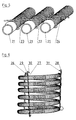
- An arrangement of three corrugated pipes (21) is located in a holding device (22) and is thereby secured against lateral slippage and distance changes against each other.
- the spacers (23) of the holding device (22) present between the formations for receiving the corrugated pipes (21) receive a fastening part (24) in such a way that it is pulled alternately through the existing loops and the existing spacers (23) move prevent the fastening part (24) in the vertical direction.
- the corrugated tubes (21) are also held in a form-fitting manner in the recesses of the holding device (22).
- a cylindrical winding (25) consists of a corrugated pipe, which should be arranged in a substantially constant diameter and distance of the individual turns to each other.
- Holding devices (26), (27) and (28) are pressed into the winding (25) and fix it.
- a securing component (29) in the holding device (27) has a securing component (30) and in the holding device (28) retracted a securing member (31), so that the winding is kept dimensionally stable.
- the number of holding devices used in wound or spirally wound lines may vary.
- the inventive method consists in the first step in that a line (1) in a holding device (2) is inserted.
- the opening width a of the holding device (2) is chosen so that it is smaller in magnitude than the smallest diameter of a line (1, 19) or a corrugated tube (10). This results in a snap-in process, by which the line (1, 19) or the corrugated tube (10) is held in a form-fitting manner.
- the line (19) is also inserted into the meander-shaped curved holding device (16; 26; 27; 28).
- a fastening part (8; 24; 29; 30; 31) is inserted into the holding device (1; 9; 13; 16; 22; 26; 27; 28) in such a way that it engages with corresponding elements of the holding device (1; 9; 13; 16; 22; 26; 27; 28) is mutually engaged and thereby held on the one hand form-fitting and a lateral displacement is excluded, so that the inserted lines can not slip out of their holder.
- the fastening part (8, 24, 29, 30, 31) laterally bent at its protruding ends or with the holding device (1, 9, 13, 16, 22, 26, 27, 28) are twisted. This avoids an unwanted shift.
- the arrangement according to the invention and the method according to the invention are used in particular when lines or line sections running side by side have to be fixed against each other.
- a plurality of juxtaposed lines can be fixed as well as the side-by-side line sections of a helically extending single line.
- cylindrical coils can be fixed by the arrangement according to the invention.
- Even multiply stacked or nested winding or special shapes can by a plurality of arrangements be fixed against each other so that a sufficient position assurance is guaranteed.
- the arrangement according to the invention and the associated method therefore make it possible, in particular, to fix lines to be introduced into containers against one another and inside the container in such a way that, for example, touches of the container walls are excluded.
- the invention thus has the advantage that lines can be fixed with little effort, in particular when used in cooperation with corrugated pipes and an axial securing is achieved with the inventive arrangement.
Landscapes
- Engineering & Computer Science (AREA)
- General Engineering & Computer Science (AREA)
- Mechanical Engineering (AREA)
- Physics & Mathematics (AREA)
- Thermal Sciences (AREA)
- Supports For Pipes And Cables (AREA)
Claims (12)
- Arrangement pour la fixation de conduites, composé d'au moins
une conduite (19) ou d'un tube ondulé (10)
et d'un dispositif de maintien (16, 22, 26, 27, 28)
dans lequel la conduite (19) ou le tube ondulé (10) se trouve en contact avec le dispositif de maintien (16, 22, 26, 27, 28) par au moins un point (3) de sa surface extérieure et se situe dans une courbure en forme de méandre (17) de celui-ci,
et le dispositif de maintien (16, 22, 26, 27, 28) fixe la conduite (19) ou le tube ondulé (10) dans au moins une direction,
caractérisé en ce que
le dispositif de maintien (16, 22, 26, 27, 28) est une pièce en forme de fil ou de bande avec des évidements formés par courbure,
la courbure en forme de méandre (17) est formée par des courbures sur des côtés opposés du dispositif de maintien (16), et la profondeur de la courbure en forme de méandre (17) est supérieure au diamètre (18) de la conduite au niveau du point de fixation,
une pièce de fixation (24) ou une pièce de blocage (29, 30, 31) en forme de tige, de bande ou de fil est en outre insérée dans les courbures en forme de méandres (17) du dispositif de maintien (16, 26, 27, 28) après l'insertion de la conduite (19) ou du tube ondulé (10), de manière à être poussée alternativement à travers les courbures du dispositif de maintien, fermant ainsi les ouvertures restantes des courbures en forme de méandres (17), et de sorte que la conduite (19) ou le tube ondulé (10) n'ont plus de degré de liberté dans la direction radiale. - Arrangement pour la fixation de conduites selon la revendication 1,
caractérisé en ce que
la conduite (19) ou le tube ondulé (10) se trouve en contact avec le dispositif de maintien au niveau de plusieurs points de sa surface extérieure ou sur une partie de son pourtour et se situe dans une courbure en forme de méandre (17) du dispositif de maintien, le dispositif de maintien (16, 22, 26, 27, 28) fixant la conduite dans au moins une direction. - Arrangement pour la fixation de conduites selon l'une des revendications 1 ou 2,
caractérisé en ce que
la courbure en forme de méandre (17) du dispositif de maintien (16, 22, 26, 27, 28) possède une largeur d'ouverture (a) inférieure au diamètre d'enveloppe (18) de la conduite au niveau du point de fixation. - Arrangement pour la fixation de conduites selon l'une des revendications 1 à 3,
caractérisé en ce que
la courbure en forme de méandre (17) possède un contour intérieur présentant une forme d'arc de cercle, ovale, de lentille ou de U, polygonale ou triangulaire. - Arrangement pour la fixation de conduites selon la revendication 4,
caractérisé en ce que
le dispositif de maintien (16, 22, 26, 27, 28) possède un oeillet (7) et/ou une courbure en forme de crochet à au moins une extrémité. - Arrangement pour la fixation de conduites selon l'une des revendications 1 à 5,
caractérisé en ce que
la conduite (19) est un tube ondulé et/ou un tuyau ondulé (10, 21) avec une enveloppe ondulée de façon parallèle ou en forme de spirale. - Arrangement pour la fixation de conduites selon l'une des revendications 1 à 6,
caractérisé en ce que
la conduite (19) est torsadée en forme de spirale et/ou de cylindre, le dispositif de maintien (16, 22, 26, 27, 28) reçoit plusieurs fois la conduite dans ses courbures en forme de méandres (17) et la maintient à distance. - Arrangement pour la fixation de conduites selon la revendication 7,
caractérisé en ce que
plusieurs dispositifs de maintien sont attribués à la conduite (19) ou au tube ondulé (10). - Procédé pour la fixation de conduites dans un arrangement pour la fixation de conduites selon les revendications 1 à 8,
caractérisé en ce que
une conduite (19), un tube ondulé (10) ou des tubes ondulés (21) sont enfoncés dans des courbures en forme de méandres (17) d'un dispositif de maintien (16 ; 26 ; 27 ; 28), et le plus petit diamètre de la conduite (19), du tube ondulé (10) ou des tubes ondulés (21) est supérieur à la largeur d'ouverture (a) de la courbure en forme de méandre (17), et
une pièce de fixation (24) est poussée à travers les pièces d'écartement (23) du dispositif de maintien (22). - Procédé pour la fixation de conduites selon la revendication 9,
caractérisé en ce que
la pièce de fixation (24) est coudée latéralement à son extrémité qui dépasse. - Procédé pour la fixation de conduites selon la revendication 10,
caractérisé en ce que
la pièce de fixation (24) est torsadée avec le dispositif de maintien (22). - Utilisation d'un arrangement pour la fixation de conduites selon l'une des revendications 1 à 8,
caractérisée en ce que
l'arrangement est utilisé pour la fixation d'une ou de plusieurs conduites adjacentes
et/ou pour la fixation de l'espacement entre des parties d'une ou de plusieurs conduites torsadées en forme de spirale ou de cylindre
et/ou pour la fixation de différentes conduites torsadées les unes contre les autres.
Applications Claiming Priority (1)
| Application Number | Priority Date | Filing Date | Title |
|---|---|---|---|
| DE202007009023U DE202007009023U1 (de) | 2007-06-26 | 2007-06-26 | Anordnung zur Fixierung von Leitungen |
Publications (3)
| Publication Number | Publication Date |
|---|---|
| EP2009337A2 EP2009337A2 (fr) | 2008-12-31 |
| EP2009337A3 EP2009337A3 (fr) | 2012-05-30 |
| EP2009337B1 true EP2009337B1 (fr) | 2014-07-23 |
Family
ID=38565287
Family Applications (1)
| Application Number | Title | Priority Date | Filing Date |
|---|---|---|---|
| EP08011638.7A Not-in-force EP2009337B1 (fr) | 2007-06-26 | 2008-06-26 | Agencement et procédé de fixation de conduites |
Country Status (2)
| Country | Link |
|---|---|
| EP (1) | EP2009337B1 (fr) |
| DE (1) | DE202007009023U1 (fr) |
Families Citing this family (6)
| Publication number | Priority date | Publication date | Assignee | Title |
|---|---|---|---|---|
| EP2211079A1 (fr) | 2009-01-23 | 2010-07-28 | AZ Pokorny S.R.O. | Système de fixation pour conduites et procédé de fixation |
| DE202009000896U1 (de) | 2009-01-23 | 2009-03-26 | Az Pokorny S.R.O. | Fixierungssystem für Leitungen und Fixierung |
| FR3006412B1 (fr) * | 2013-05-28 | 2015-06-12 | Snecma | Dispositif d'entretoisement d'elements de forme allongee d'une turbomachine d'aeronef |
| CN111430492B (zh) * | 2020-05-13 | 2025-02-14 | 中重能(南通)新能源有限公司 | 一种用于太阳能电热采集双面带沟槽的安装板 |
| EP4071436B1 (fr) | 2021-04-08 | 2023-08-02 | Daikin Europe N.V. | Fixation et procédé de fixation d'un tube d'un échangeur de chaleur de type bobine |
| DE102023108374A1 (de) * | 2023-03-31 | 2024-10-02 | Alleima Engineering GmbH | Wärmetauscher |
Family Cites Families (9)
| Publication number | Priority date | Publication date | Assignee | Title |
|---|---|---|---|---|
| DD247965A1 (de) | 1986-04-08 | 1987-07-22 | Bauakademie Ddr | Verfahren zur herstellung von rohrbuendeln fuer waermeuebertrager |
| DE3928558A1 (de) | 1989-08-29 | 1991-03-07 | Raimund Dr Rer Nat Oberschmid | Luft-luft-waermetauscher mit rippenrohr-klemmbloecken und spannvorrichtung bes. fuer landwirtschaftliche staelle |
| US5016706A (en) | 1989-10-30 | 1991-05-21 | Carrier Corporation | Heat exchanger tube support |
| US4991801A (en) | 1990-03-01 | 1991-02-12 | Trumbull Terry N | Universal support strap |
| US5319837A (en) | 1992-10-13 | 1994-06-14 | Bundy Corporation | Tube bundle clip |
| DE19604974A1 (de) | 1996-02-02 | 1997-08-07 | Kienast Johannes | Abstandhalter zur Fixierung von parallel im Abstand angeordneten flexiblen Kunststoffrohren |
| US6311936B1 (en) | 1999-07-30 | 2001-11-06 | Maytag Corporation | Hose retainer |
| FR2811816B1 (fr) | 2000-07-13 | 2002-10-11 | Cit Alcatel | Support pour elements filiformes de faible diametre et faisceau d'elements filiformes relies entre eux par ce support |
| AT7834U1 (de) | 2004-10-08 | 2005-09-26 | Bremstaller Ges M B H & Co Kg | Wärmetauscher für einen warmwasserbehälter |
-
2007
- 2007-06-26 DE DE202007009023U patent/DE202007009023U1/de not_active Expired - Lifetime
-
2008
- 2008-06-26 EP EP08011638.7A patent/EP2009337B1/fr not_active Not-in-force
Also Published As
| Publication number | Publication date |
|---|---|
| EP2009337A3 (fr) | 2012-05-30 |
| DE202007009023U1 (de) | 2007-10-04 |
| EP2009337A2 (fr) | 2008-12-31 |
Similar Documents
| Publication | Publication Date | Title |
|---|---|---|
| EP2009337B1 (fr) | Agencement et procédé de fixation de conduites | |
| AT408139B (de) | Installationseinrichtung für rohrleitungen | |
| EP2461078B1 (fr) | Agrafe permettant de maintenir au moins un objet, en particulier un câble | |
| DE3019303C2 (de) | Rohr-Klips | |
| EP2211079A1 (fr) | Système de fixation pour conduites et procédé de fixation | |
| DE102015100227B4 (de) | Schlauchhaltestruktur für ein Wärmetauschermodul für Warmwasserspeicher | |
| EP1253366A1 (fr) | Tuyau ondulé en plastique | |
| EP1219905A2 (fr) | Chauffage par le sol | |
| EP1835214B1 (fr) | Accumulateur thermique | |
| EP2562459A1 (fr) | Crochet de tuyau | |
| EP1724508B1 (fr) | Tuyau | |
| DE2715394A1 (de) | Halterung fuer heizungsrohre | |
| WO2024165448A1 (fr) | Élément de maintien pour fixer les câbles d'un système photovoltaïque | |
| DE3421095C2 (de) | Dämpfungshalterung, insbesondere für dynamischen Belastungen und beträchtlichen Temperaturschwankungen ausgesetzte dünnwandige Rohrleitungen | |
| DE202014100342U1 (de) | Flächenheizung | |
| DE2607474A1 (de) | Rohrleitung fuer fussbodenheizung | |
| AT977U1 (de) | Wärmedämmendes element für körper, insbesondere für warmwasserspeicher | |
| EP2643622B1 (fr) | Système de fixation pour une file de conduites juxtaposées | |
| AT406908B (de) | Aufsteckbare lamellen für nachträglich veränderbare kleinkonvektoren | |
| DE102005012868B3 (de) | Halte- und Führungseinrichtung für Wärmetauscherelemente | |
| DE10060971C1 (de) | Deckenelement | |
| EP0795710A1 (fr) | Conduite ondulée pour medium sous pression | |
| DE102022110103B3 (de) | Befestigungsklammer für ein Kabeltragsystem sowie Kabeltragsystem mit einer solchen Befestigungsklammer | |
| DE20021612U1 (de) | Fußbodenheizung | |
| DE202006016308U1 (de) | Vorrichtung zur Entnahme von Wärme |
Legal Events
| Date | Code | Title | Description |
|---|---|---|---|
| PUAI | Public reference made under article 153(3) epc to a published international application that has entered the european phase |
Free format text: ORIGINAL CODE: 0009012 |
|
| AK | Designated contracting states |
Kind code of ref document: A2 Designated state(s): AT BE BG CH CY CZ DE DK EE ES FI FR GB GR HR HU IE IS IT LI LT LU LV MC MT NL NO PL PT RO SE SI SK TR |
|
| AX | Request for extension of the european patent |
Extension state: AL BA MK RS |
|
| RAP1 | Party data changed (applicant data changed or rights of an application transferred) |
Owner name: AZ VERMOEGENSVERWALTUNG GMBH & CO. KG. |
|
| PUAL | Search report despatched |
Free format text: ORIGINAL CODE: 0009013 |
|
| AK | Designated contracting states |
Kind code of ref document: A3 Designated state(s): AT BE BG CH CY CZ DE DK EE ES FI FR GB GR HR HU IE IS IT LI LT LU LV MC MT NL NO PL PT RO SE SI SK TR |
|
| AX | Request for extension of the european patent |
Extension state: AL BA MK RS |
|
| RIC1 | Information provided on ipc code assigned before grant |
Ipc: F16L 3/133 20060101ALI20120423BHEP Ipc: F16L 3/13 20060101ALI20120423BHEP Ipc: F16L 3/223 20060101ALI20120423BHEP Ipc: F16L 3/02 20060101AFI20120423BHEP Ipc: F28F 9/013 20060101ALI20120423BHEP |
|
| 17P | Request for examination filed |
Effective date: 20121018 |
|
| 17Q | First examination report despatched |
Effective date: 20121214 |
|
| AKX | Designation fees paid |
Designated state(s): AT BE BG CH CY CZ DE DK EE ES FI FR GB GR HR HU IE IS IT LI LT LU LV MC MT NL NO PL PT RO SE SI SK TR |
|
| REG | Reference to a national code |
Ref country code: DE Ref legal event code: R079 Ref document number: 502008012029 Country of ref document: DE Free format text: PREVIOUS MAIN CLASS: F16L0003020000 Ipc: F28D0007020000 |
|
| RIC1 | Information provided on ipc code assigned before grant |
Ipc: F28D 7/02 20060101AFI20131025BHEP Ipc: F16L 3/133 20060101ALI20131025BHEP Ipc: F16L 3/223 20060101ALI20131025BHEP Ipc: F28F 9/013 20060101ALI20131025BHEP Ipc: F28F 1/08 20060101ALI20131025BHEP Ipc: F16L 3/13 20060101ALI20131025BHEP |
|
| GRAP | Despatch of communication of intention to grant a patent |
Free format text: ORIGINAL CODE: EPIDOSNIGR1 |
|
| INTG | Intention to grant announced |
Effective date: 20140212 |
|
| GRAS | Grant fee paid |
Free format text: ORIGINAL CODE: EPIDOSNIGR3 |
|
| GRAP | Despatch of communication of intention to grant a patent |
Free format text: ORIGINAL CODE: EPIDOSNIGR1 |
|
| GRAA | (expected) grant |
Free format text: ORIGINAL CODE: 0009210 |
|
| INTG | Intention to grant announced |
Effective date: 20140603 |
|
| AK | Designated contracting states |
Kind code of ref document: B1 Designated state(s): AT BE BG CH CY CZ DE DK EE ES FI FR GB GR HR HU IE IS IT LI LT LU LV MC MT NL NO PL PT RO SE SI SK TR |
|
| REG | Reference to a national code |
Ref country code: GB Ref legal event code: FG4D Free format text: NOT ENGLISH |
|
| REG | Reference to a national code |
Ref country code: CH Ref legal event code: EP |
|
| REG | Reference to a national code |
Ref country code: IE Ref legal event code: FG4D Free format text: LANGUAGE OF EP DOCUMENT: GERMAN |
|
| REG | Reference to a national code |
Ref country code: AT Ref legal event code: REF Ref document number: 679105 Country of ref document: AT Kind code of ref document: T Effective date: 20140815 |
|
| REG | Reference to a national code |
Ref country code: DE Ref legal event code: R096 Ref document number: 502008012029 Country of ref document: DE Effective date: 20140904 |
|
| REG | Reference to a national code |
Ref country code: NL Ref legal event code: VDEP Effective date: 20140723 |
|
| REG | Reference to a national code |
Ref country code: LT Ref legal event code: MG4D |
|
| PG25 | Lapsed in a contracting state [announced via postgrant information from national office to epo] |
Ref country code: GR Free format text: LAPSE BECAUSE OF FAILURE TO SUBMIT A TRANSLATION OF THE DESCRIPTION OR TO PAY THE FEE WITHIN THE PRESCRIBED TIME-LIMIT Effective date: 20141024 Ref country code: ES Free format text: LAPSE BECAUSE OF FAILURE TO SUBMIT A TRANSLATION OF THE DESCRIPTION OR TO PAY THE FEE WITHIN THE PRESCRIBED TIME-LIMIT Effective date: 20140723 Ref country code: SE Free format text: LAPSE BECAUSE OF FAILURE TO SUBMIT A TRANSLATION OF THE DESCRIPTION OR TO PAY THE FEE WITHIN THE PRESCRIBED TIME-LIMIT Effective date: 20140723 Ref country code: FI Free format text: LAPSE BECAUSE OF FAILURE TO SUBMIT A TRANSLATION OF THE DESCRIPTION OR TO PAY THE FEE WITHIN THE PRESCRIBED TIME-LIMIT Effective date: 20140723 Ref country code: LT Free format text: LAPSE BECAUSE OF FAILURE TO SUBMIT A TRANSLATION OF THE DESCRIPTION OR TO PAY THE FEE WITHIN THE PRESCRIBED TIME-LIMIT Effective date: 20140723 Ref country code: NO Free format text: LAPSE BECAUSE OF FAILURE TO SUBMIT A TRANSLATION OF THE DESCRIPTION OR TO PAY THE FEE WITHIN THE PRESCRIBED TIME-LIMIT Effective date: 20141023 Ref country code: BG Free format text: LAPSE BECAUSE OF FAILURE TO SUBMIT A TRANSLATION OF THE DESCRIPTION OR TO PAY THE FEE WITHIN THE PRESCRIBED TIME-LIMIT Effective date: 20141023 Ref country code: PT Free format text: LAPSE BECAUSE OF FAILURE TO SUBMIT A TRANSLATION OF THE DESCRIPTION OR TO PAY THE FEE WITHIN THE PRESCRIBED TIME-LIMIT Effective date: 20141124 |
|
| PG25 | Lapsed in a contracting state [announced via postgrant information from national office to epo] |
Ref country code: LV Free format text: LAPSE BECAUSE OF FAILURE TO SUBMIT A TRANSLATION OF THE DESCRIPTION OR TO PAY THE FEE WITHIN THE PRESCRIBED TIME-LIMIT Effective date: 20140723 Ref country code: HR Free format text: LAPSE BECAUSE OF FAILURE TO SUBMIT A TRANSLATION OF THE DESCRIPTION OR TO PAY THE FEE WITHIN THE PRESCRIBED TIME-LIMIT Effective date: 20140723 Ref country code: PL Free format text: LAPSE BECAUSE OF FAILURE TO SUBMIT A TRANSLATION OF THE DESCRIPTION OR TO PAY THE FEE WITHIN THE PRESCRIBED TIME-LIMIT Effective date: 20140723 Ref country code: IS Free format text: LAPSE BECAUSE OF FAILURE TO SUBMIT A TRANSLATION OF THE DESCRIPTION OR TO PAY THE FEE WITHIN THE PRESCRIBED TIME-LIMIT Effective date: 20141123 Ref country code: NL Free format text: LAPSE BECAUSE OF FAILURE TO SUBMIT A TRANSLATION OF THE DESCRIPTION OR TO PAY THE FEE WITHIN THE PRESCRIBED TIME-LIMIT Effective date: 20140723 Ref country code: CY Free format text: LAPSE BECAUSE OF FAILURE TO SUBMIT A TRANSLATION OF THE DESCRIPTION OR TO PAY THE FEE WITHIN THE PRESCRIBED TIME-LIMIT Effective date: 20140723 |
|
| REG | Reference to a national code |
Ref country code: DE Ref legal event code: R097 Ref document number: 502008012029 Country of ref document: DE |
|
| PG25 | Lapsed in a contracting state [announced via postgrant information from national office to epo] |
Ref country code: RO Free format text: LAPSE BECAUSE OF FAILURE TO SUBMIT A TRANSLATION OF THE DESCRIPTION OR TO PAY THE FEE WITHIN THE PRESCRIBED TIME-LIMIT Effective date: 20140723 Ref country code: EE Free format text: LAPSE BECAUSE OF FAILURE TO SUBMIT A TRANSLATION OF THE DESCRIPTION OR TO PAY THE FEE WITHIN THE PRESCRIBED TIME-LIMIT Effective date: 20140723 Ref country code: DK Free format text: LAPSE BECAUSE OF FAILURE TO SUBMIT A TRANSLATION OF THE DESCRIPTION OR TO PAY THE FEE WITHIN THE PRESCRIBED TIME-LIMIT Effective date: 20140723 Ref country code: CZ Free format text: LAPSE BECAUSE OF FAILURE TO SUBMIT A TRANSLATION OF THE DESCRIPTION OR TO PAY THE FEE WITHIN THE PRESCRIBED TIME-LIMIT Effective date: 20140723 Ref country code: IT Free format text: LAPSE BECAUSE OF FAILURE TO SUBMIT A TRANSLATION OF THE DESCRIPTION OR TO PAY THE FEE WITHIN THE PRESCRIBED TIME-LIMIT Effective date: 20140723 Ref country code: SK Free format text: LAPSE BECAUSE OF FAILURE TO SUBMIT A TRANSLATION OF THE DESCRIPTION OR TO PAY THE FEE WITHIN THE PRESCRIBED TIME-LIMIT Effective date: 20140723 |
|
| PLBE | No opposition filed within time limit |
Free format text: ORIGINAL CODE: 0009261 |
|
| STAA | Information on the status of an ep patent application or granted ep patent |
Free format text: STATUS: NO OPPOSITION FILED WITHIN TIME LIMIT |
|
| 26N | No opposition filed |
Effective date: 20150424 |
|
| PG25 | Lapsed in a contracting state [announced via postgrant information from national office to epo] |
Ref country code: SI Free format text: LAPSE BECAUSE OF FAILURE TO SUBMIT A TRANSLATION OF THE DESCRIPTION OR TO PAY THE FEE WITHIN THE PRESCRIBED TIME-LIMIT Effective date: 20140723 |
|
| PG25 | Lapsed in a contracting state [announced via postgrant information from national office to epo] |
Ref country code: MC Free format text: LAPSE BECAUSE OF FAILURE TO SUBMIT A TRANSLATION OF THE DESCRIPTION OR TO PAY THE FEE WITHIN THE PRESCRIBED TIME-LIMIT Effective date: 20140723 |
|
| REG | Reference to a national code |
Ref country code: CH Ref legal event code: PL |
|
| PG25 | Lapsed in a contracting state [announced via postgrant information from national office to epo] |
Ref country code: LU Free format text: LAPSE BECAUSE OF FAILURE TO SUBMIT A TRANSLATION OF THE DESCRIPTION OR TO PAY THE FEE WITHIN THE PRESCRIBED TIME-LIMIT Effective date: 20150626 |
|
| REG | Reference to a national code |
Ref country code: IE Ref legal event code: MM4A |
|
| PG25 | Lapsed in a contracting state [announced via postgrant information from national office to epo] |
Ref country code: IE Free format text: LAPSE BECAUSE OF NON-PAYMENT OF DUE FEES Effective date: 20150626 Ref country code: CH Free format text: LAPSE BECAUSE OF NON-PAYMENT OF DUE FEES Effective date: 20150630 Ref country code: LI Free format text: LAPSE BECAUSE OF NON-PAYMENT OF DUE FEES Effective date: 20150630 |
|
| REG | Reference to a national code |
Ref country code: FR Ref legal event code: PLFP Year of fee payment: 9 |
|
| PG25 | Lapsed in a contracting state [announced via postgrant information from national office to epo] |
Ref country code: MT Free format text: LAPSE BECAUSE OF FAILURE TO SUBMIT A TRANSLATION OF THE DESCRIPTION OR TO PAY THE FEE WITHIN THE PRESCRIBED TIME-LIMIT Effective date: 20140723 |
|
| REG | Reference to a national code |
Ref country code: FR Ref legal event code: PLFP Year of fee payment: 10 |
|
| PG25 | Lapsed in a contracting state [announced via postgrant information from national office to epo] |
Ref country code: HU Free format text: LAPSE BECAUSE OF FAILURE TO SUBMIT A TRANSLATION OF THE DESCRIPTION OR TO PAY THE FEE WITHIN THE PRESCRIBED TIME-LIMIT; INVALID AB INITIO Effective date: 20080626 |
|
| PG25 | Lapsed in a contracting state [announced via postgrant information from national office to epo] |
Ref country code: BE Free format text: LAPSE BECAUSE OF NON-PAYMENT OF DUE FEES Effective date: 20150630 |
|
| PGFP | Annual fee paid to national office [announced via postgrant information from national office to epo] |
Ref country code: GB Payment date: 20170504 Year of fee payment: 10 Ref country code: DE Payment date: 20170424 Year of fee payment: 10 Ref country code: FR Payment date: 20170516 Year of fee payment: 10 |
|
| PG25 | Lapsed in a contracting state [announced via postgrant information from national office to epo] |
Ref country code: TR Free format text: LAPSE BECAUSE OF FAILURE TO SUBMIT A TRANSLATION OF THE DESCRIPTION OR TO PAY THE FEE WITHIN THE PRESCRIBED TIME-LIMIT Effective date: 20140723 |
|
| PGFP | Annual fee paid to national office [announced via postgrant information from national office to epo] |
Ref country code: AT Payment date: 20170424 Year of fee payment: 10 |
|
| REG | Reference to a national code |
Ref country code: DE Ref legal event code: R119 Ref document number: 502008012029 Country of ref document: DE |
|
| REG | Reference to a national code |
Ref country code: AT Ref legal event code: MM01 Ref document number: 679105 Country of ref document: AT Kind code of ref document: T Effective date: 20180626 |
|
| GBPC | Gb: european patent ceased through non-payment of renewal fee |
Effective date: 20180626 |
|
| PG25 | Lapsed in a contracting state [announced via postgrant information from national office to epo] |
Ref country code: DE Free format text: LAPSE BECAUSE OF NON-PAYMENT OF DUE FEES Effective date: 20190101 Ref country code: AT Free format text: LAPSE BECAUSE OF NON-PAYMENT OF DUE FEES Effective date: 20180626 Ref country code: GB Free format text: LAPSE BECAUSE OF NON-PAYMENT OF DUE FEES Effective date: 20180626 Ref country code: FR Free format text: LAPSE BECAUSE OF NON-PAYMENT OF DUE FEES Effective date: 20180630 |