EP2009359A2 - Installation thermique solaire et procédé de fonctionnement d'une telle installation - Google Patents
Installation thermique solaire et procédé de fonctionnement d'une telle installation Download PDFInfo
- Publication number
- EP2009359A2 EP2009359A2 EP08011307A EP08011307A EP2009359A2 EP 2009359 A2 EP2009359 A2 EP 2009359A2 EP 08011307 A EP08011307 A EP 08011307A EP 08011307 A EP08011307 A EP 08011307A EP 2009359 A2 EP2009359 A2 EP 2009359A2
- Authority
- EP
- European Patent Office
- Prior art keywords
- solar
- line
- pump
- temperature
- flow
- Prior art date
- Legal status (The legal status is an assumption and is not a legal conclusion. Google has not performed a legal analysis and makes no representation as to the accuracy of the status listed.)
- Granted
Links
Images

Classifications
-
- F—MECHANICAL ENGINEERING; LIGHTING; HEATING; WEAPONS; BLASTING
- F24—HEATING; RANGES; VENTILATING
- F24D—DOMESTIC- OR SPACE-HEATING SYSTEMS, e.g. CENTRAL HEATING SYSTEMS; DOMESTIC HOT-WATER SUPPLY SYSTEMS; ELEMENTS OR COMPONENTS THEREFOR
- F24D19/00—Details
- F24D19/10—Arrangement or mounting of control or safety devices
- F24D19/1006—Arrangement or mounting of control or safety devices for water heating systems
- F24D19/1051—Arrangement or mounting of control or safety devices for water heating systems for domestic hot water
- F24D19/1057—Arrangement or mounting of control or safety devices for water heating systems for domestic hot water the system uses solar energy
-
- Y—GENERAL TAGGING OF NEW TECHNOLOGICAL DEVELOPMENTS; GENERAL TAGGING OF CROSS-SECTIONAL TECHNOLOGIES SPANNING OVER SEVERAL SECTIONS OF THE IPC; TECHNICAL SUBJECTS COVERED BY FORMER USPC CROSS-REFERENCE ART COLLECTIONS [XRACs] AND DIGESTS
- Y02—TECHNOLOGIES OR APPLICATIONS FOR MITIGATION OR ADAPTATION AGAINST CLIMATE CHANGE
- Y02B—CLIMATE CHANGE MITIGATION TECHNOLOGIES RELATED TO BUILDINGS, e.g. HOUSING, HOUSE APPLIANCES OR RELATED END-USER APPLICATIONS
- Y02B10/00—Integration of renewable energy sources in buildings
- Y02B10/20—Solar thermal
-
- Y—GENERAL TAGGING OF NEW TECHNOLOGICAL DEVELOPMENTS; GENERAL TAGGING OF CROSS-SECTIONAL TECHNOLOGIES SPANNING OVER SEVERAL SECTIONS OF THE IPC; TECHNICAL SUBJECTS COVERED BY FORMER USPC CROSS-REFERENCE ART COLLECTIONS [XRACs] AND DIGESTS
- Y02—TECHNOLOGIES OR APPLICATIONS FOR MITIGATION OR ADAPTATION AGAINST CLIMATE CHANGE
- Y02B—CLIMATE CHANGE MITIGATION TECHNOLOGIES RELATED TO BUILDINGS, e.g. HOUSING, HOUSE APPLIANCES OR RELATED END-USER APPLICATIONS
- Y02B10/00—Integration of renewable energy sources in buildings
- Y02B10/70—Hybrid systems, e.g. uninterruptible or back-up power supplies integrating renewable energies
Definitions
- the invention relates to a solar thermal system and a method for operating such a system.
- a solar thermal system basically consists of solar collectors, which capture solar energy and deliver it to a heat transfer medium (eg water-glycol, water-ethanol or water), one or more storage tanks and a closed circuit, which transports the heat absorbed in the solar collector to the storage tank Control that controls the circulation of the heat transfer medium (brine), with appropriate temperature differences from the solar collector to the store.
- the brine is heated by the solar radiation in the solar collector and then fed through the brine circuit to the memory. Subsequently, the solar heat can be used, for example, for hot water preparation, heating support or swimming pool heating.
- a simple temperature difference controller is sufficient for the regulation of a small solar thermal system for hot water production.
- the controller uses two temperature sensors to determine when the temperature at the collector outlet is higher than at the height
- the temperature of the solar circuit heat exchanger measured in the storage tank is and then sets the solar circuit circulation pump in operation.
- the solar controllers are set so that a temperature difference of about 5 - 8 K is ensured between the solar collector and the memory for the pump start. If this usually drops by 2 to 3 K, the circulation pump is put out of operation again by the solar controller.
- this setting of the solar controller problems can occur when starting the system in which the system does not start or shut down too early. Thus, after the pump starts, cold liquid enters the solar collector, which flows through it and leaves it heated again.
- the temperature in the collector drops rapidly again. Due to the present temperature difference may occur according to the prior art for switching off the pump. If the pump continues to run, the temperature rises again, since the hot liquid, which lingered in the solar collector at the pump start, flows back into the solar collector after flowing through the reservoir. Only after some upheavals does a quasi-stationary state arise.
- the invention has for its object to provide a comparison with the prior art improved solar thermal system and a method available, whereby the installation of the solar thermal system simplified and the operation is optimized.
- a solar station for connecting at least one solar collector and a storage is constructed such that it contains a control and flow and return lines in a single unit, wherein temperature sensor disposed in each of the lines and a pump in one of the lines are.
- the individual hydraulic components, actuators, sensors and controllers are locally in a solar station merged, so that a pre-wiring of the solar station is possible from the factory.
- the installation time is largely reduced to the hydraulic connection of the solar collector and the hot water tank and avoided any errors during installation.
- the maintenance and repair of the system are simplified.
- the arrangement of the collector sensor in the solar station is the simplified electrical and hydraulic installation of the system. This results from the position of the collector sensor in the flow of the solar thermal system, whereby a possible swapping of the supply and return line to or from the collector during installation has no effect on the temperature sensor.
- the temperature sensor is always located in the flow of the solar station and is always traversed by a liquid that has only flowed through the collector, i. preheated. An effect on the behavior of the control, by reversed supply and return lines, is thus excluded.
- the temperature detection of the solar circuit flow and return in the system takes place as close as possible to the solar storage tank to be loaded, so that efficient energy storage in the solar storage tank can be ensured.
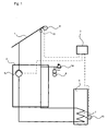
- FIG. 1 shows a solar thermal system of the prior art, which consists essentially of a solar collector 1, a solar station 2, a regulator 3, an expansion vessel 4, a pump 5, a memory 6 and a heat exchanger 7.
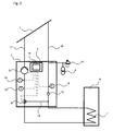
- FIG. 2 illustrated solar thermal system according to the invention shows a solar station 2, to which a solar collector 1 and a storage device 6 are connected.
- the solar station 2 includes in a unit a flow line 16 and a return line 17. Between the flow line 16 and the return line 17 is a bypass line 18.
- a switching valve 8 in the return line 17 can be switched such that the solar collector 1 either with the bypass line 18th or connected to the storage device 6.
- In the return line 17 is also a pump 5 and a temperature sensor 10.
- In the flow is a temperature sensor 9.
- the switching valve 8 and / or the pump 5 could also be located in the flow line 16.
- the memory 6 and the solar collector 1 is flowed through as in a conventional system of the solar fluid, in a further position, the memory 6 is bypassed via the bypass line 18 and only flows through the solar collector 1, so that the solar fluid is pumped by the pump only through the solar collector 1 and not through the memory 6.
- a storage charge does not take place in this state, but a collector temperature measurement is possible in this phase in the solar station 2.
- the conventional solar thermal systems conventional solar collector sensor for the temperature measurement on the solar collector can be omitted.
- the switching valve 8 When starting the pump 5, the switching valve 8 is in the position in which the solar fluid is not pumped through the memory 6, but through the bypass line 18. Only after the temperature measured by means of the temperature sensor 9 exceeds a predetermined temperature T L in the flow, the changeover valve 8 switches to storage charge. Thus, no unnecessary cooling takes place in the memory 6.
- the return temperature of the memory 6 is measured in the solar station 2 by the temperature measured by means of temperature sensor 10 is detected after a certain period of time. Since the memory 6 has a very sluggish temperature behavior, the shutdown of the pump 5 can be realized via the return temperature, which is measured in the solar station 2. The shutdown of the pump 5 is dependent on the one hand on the difference between the collector temperature T 1 (flow) and the storage temperature T 2 (return), and on the other - on the absolute value of the measured temperature.
- a start of the pump 5 is performed with the solar station 2 according to the invention at predefined intervals in order to measure the corresponding flow temperature in the solar station 2 can.
- the solar collector 1 flows through the solar collector.
- a subsequent possible storage charge is checked by regulation 3.
- a certain minimum running time of the pump 5 can be taken into account, so that the entire system is purged for a certain time.
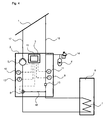
- FIG. 3 is a solar thermal system shown according to a further embodiment, in addition to the solar thermal system from the FIG. 2 various settings by means of a control unit with displays 19 integrated in the solar station 2 can be made and displayed.
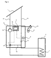
- the solar thermal plant in the FIG. 4 has in addition to the operating unit with display 19 via a pressure sensor 11, both being integrated in the solar station 2. With the pressure sensor 11 pressure measurements to increase the reliability can be made.
- FIG. 5 shows a further embodiment of the solar thermal system according to the invention.
- This system has only one temperature sensor 9, arranged in the flow line 16 downstream of the solar collector. 1
- FIGs 2-5 is also an expansion vessel 4 shown with a safety valve 14 which is connected to the flow line 16 or the return line 17. This ensures a stable pressure behavior of the solar fluid in the system.
- a first circuit of the solar collector 1 and the solar station 2 and a second circuit of the solar collector 1, the solar station 2 and the memory 6 is formed.
- the pump is switched off and the changeover valve 8 is switched such that the heat transfer medium flows only through the solar collector 1.
- the switching valve 8 is switched so that the heat transfer medium also flows through the memory 6 and a storage charge can be carried out.
- the pump 5 is turned off.
- the switching valve 8 is again switched such that the bypass line 18, the supply line 16 connects to the return line 17 and the pump 5 is turned on again.
- a speed control of the pump is conceivable at this point.
- different temperature values or temperature changes would cause different rotational speeds of the pump.
- a speed control can take place in addition to the temperature control.
- the solar station according to the invention acts as a main station, as a so-called "master”.
- the solar station according to the invention can function as a slave station, as a so-called “slave”, if further control components are used in the overall system.
Landscapes
- Engineering & Computer Science (AREA)
- Chemical & Material Sciences (AREA)
- Sustainable Development (AREA)
- Sustainable Energy (AREA)
- Physics & Mathematics (AREA)
- Thermal Sciences (AREA)
- Life Sciences & Earth Sciences (AREA)
- Combustion & Propulsion (AREA)
- Mechanical Engineering (AREA)
- General Engineering & Computer Science (AREA)
- Heat-Pump Type And Storage Water Heaters (AREA)
- Central Heating Systems (AREA)
- Engine Equipment That Uses Special Cycles (AREA)
- Domestic Hot-Water Supply Systems And Details Of Heating Systems (AREA)
Applications Claiming Priority (2)
| Application Number | Priority Date | Filing Date | Title |
|---|---|---|---|
| DE102007030363 | 2007-06-29 | ||
| AT13282007 | 2007-08-27 |
Publications (3)
| Publication Number | Publication Date |
|---|---|
| EP2009359A2 true EP2009359A2 (fr) | 2008-12-31 |
| EP2009359A3 EP2009359A3 (fr) | 2014-08-13 |
| EP2009359B1 EP2009359B1 (fr) | 2016-09-14 |
Family
ID=39926606
Family Applications (1)
| Application Number | Title | Priority Date | Filing Date |
|---|---|---|---|
| EP08011307.9A Not-in-force EP2009359B1 (fr) | 2007-06-29 | 2008-06-21 | procédé de fonctionnement d'une installation thermique solaire |
Country Status (3)
| Country | Link |
|---|---|
| EP (1) | EP2009359B1 (fr) |
| DE (1) | DE102008029527A1 (fr) |
| ES (1) | ES2606049T3 (fr) |
Cited By (4)
| Publication number | Priority date | Publication date | Assignee | Title |
|---|---|---|---|---|
| EP2551604A1 (fr) * | 2011-07-29 | 2013-01-30 | Robert Bosch GmbH | Installation solaire |
| WO2015086883A1 (fr) * | 2013-12-13 | 2015-06-18 | Abengoa Solar New Technologies, S.A. | Station de production directe de vapeur et procédé de fonctionnement de cette station |
| DE102015222909A1 (de) | 2015-11-20 | 2017-05-24 | Vaillant Gmbh | Verfahren zur Bestimmung des Frostschutzmittelgehalts eines Wärmeträgermediums in einem hydraulischen Kreislauf eines Heizsystems |
| WO2017088019A1 (fr) * | 2015-11-26 | 2017-06-01 | Nivaru B.V. | Circuit de transfert de chaleur et soupape destinée à être utilisée dans ledit circuit |
Families Citing this family (3)
| Publication number | Priority date | Publication date | Assignee | Title |
|---|---|---|---|---|
| DE202010010743U1 (de) | 2010-07-28 | 2011-11-11 | Robert Bosch Gmbh | Solaranlage |
| DE102013111627A1 (de) | 2013-10-22 | 2015-06-03 | Viessmann Werke Gmbh & Co Kg | Verfahren zum Betrieb einer Solaranlage |
| DE102016112784A1 (de) * | 2016-07-12 | 2018-01-18 | Viessmann Werke Gmbh & Co Kg | Kollektorfeld, Energieversorgungssystem mit einem Kollektorfeld sowie Verfahren zum Betreiben eines Energieversorgungssystems |
Family Cites Families (7)
| Publication number | Priority date | Publication date | Assignee | Title |
|---|---|---|---|---|
| DE2907657A1 (de) * | 1979-02-27 | 1980-08-28 | Messerschmitt Boelkow Blohm | Solaranlage fuer die direkte brauchwassererwaermung |
| FR2496847A1 (fr) * | 1980-12-19 | 1982-06-25 | Mecelec Sa | Perfectionnements aux installations de chauffage utilisant la chaleur rayonnee par le soleil |
| IT8321749U1 (it) * | 1983-05-05 | 1984-11-05 | Baldini Alessandro | Unita' modulare di controllo e pompaggio per centrali termiche e simili. |
| DE19643530A1 (de) * | 1996-10-23 | 1998-10-29 | Esaa Boehringer Gmbh | Steuerung zur Erhöhung des Anlagenwirkungsgrades thermischer Solaranlagen mit Bypass-Schaltung im Kollektorkreis und diskontinuierlichem Pumpenbetrieb |
| DE29722530U1 (de) * | 1997-12-19 | 1998-06-10 | Ulrich Brunner Ofen- und Heiztechnik Gesellschaft für Guß- und Stahlkonstruktionen mbH, 84307 Eggenfelden | Heizungssteuerungsanlage |
| DE20103062U1 (de) * | 2001-02-21 | 2002-07-04 | Alfons Renn GmbH, 87474 Buchenberg | Verteilerstation für eine Heizungs- und Wasserversorgungsanlage |
| AT412505B (de) * | 2003-04-09 | 2005-03-25 | Siemens Ag Oesterreich | Solaranlage |
-
2008
- 2008-06-21 ES ES08011307.9T patent/ES2606049T3/es active Active
- 2008-06-21 DE DE102008029527A patent/DE102008029527A1/de not_active Withdrawn
- 2008-06-21 EP EP08011307.9A patent/EP2009359B1/fr not_active Not-in-force
Cited By (5)
| Publication number | Priority date | Publication date | Assignee | Title |
|---|---|---|---|---|
| EP2551604A1 (fr) * | 2011-07-29 | 2013-01-30 | Robert Bosch GmbH | Installation solaire |
| WO2015086883A1 (fr) * | 2013-12-13 | 2015-06-18 | Abengoa Solar New Technologies, S.A. | Station de production directe de vapeur et procédé de fonctionnement de cette station |
| DE102015222909A1 (de) | 2015-11-20 | 2017-05-24 | Vaillant Gmbh | Verfahren zur Bestimmung des Frostschutzmittelgehalts eines Wärmeträgermediums in einem hydraulischen Kreislauf eines Heizsystems |
| EP3190345A1 (fr) | 2015-11-20 | 2017-07-12 | Vaillant GmbH | Procédé de détermination de la teneur en antigel d'un fluide caloporteur dans un circuit hydraulique d'un système de chauffage |
| WO2017088019A1 (fr) * | 2015-11-26 | 2017-06-01 | Nivaru B.V. | Circuit de transfert de chaleur et soupape destinée à être utilisée dans ledit circuit |
Also Published As
| Publication number | Publication date |
|---|---|
| EP2009359A3 (fr) | 2014-08-13 |
| ES2606049T3 (es) | 2017-03-17 |
| EP2009359B1 (fr) | 2016-09-14 |
| DE102008029527A1 (de) | 2009-01-02 |
Similar Documents
| Publication | Publication Date | Title |
|---|---|---|
| EP2009359B1 (fr) | procédé de fonctionnement d'une installation thermique solaire | |
| EP2806168B1 (fr) | Module de pompe de circulation et installation thermosolaire le comprenant | |
| DE10231877A1 (de) | Konstanttemperaturflüssigkeitszirkuliervorrichtung | |
| DE3517218A1 (de) | Verfahren zum betreiben einer dampfkompressionskaelteanlage und anordnung zum steuern derselben | |
| WO2014205468A1 (fr) | Installation de production d'eau chaude | |
| EP1950499B1 (fr) | Procédé destiné au fonctionnement d'une installation thermique solaire | |
| DE2507281A1 (de) | Elektrische zentral-speicherheizung | |
| EP2000742B1 (fr) | Mélangeur pour configurer la température de l'eau chaude | |
| EP2213952A2 (fr) | Installation de chauffage solaire, procédé et dispositif de diagnostic d'une quantité d'air dans un circuit de fluide solaire rempli de fluide solaire et d'entraînement d'une installation de chauffage solaire | |
| DE3441912A1 (de) | Verfahren zum automatischen abtauen eines luftbeaufschlagten verdampfers einer waermepumpe | |
| EP0676682B1 (fr) | Capteur solaire avec surveillance de panne | |
| DE102006028521A1 (de) | Heizanlage und Verfahren zum Betreiben einer solchen Heizanlage | |
| EP2551604A1 (fr) | Installation solaire | |
| DE102013012724A1 (de) | Vorrichtung zur Erwärmung von Heizwasser für eine Warmwasserbereitung | |
| DE2948088A1 (de) | Einrichtung zum kuehlen und beheizen von druckfluessigkeiten | |
| EP0405136B1 (fr) | Installation pour la mise à disposition d'eau chaude | |
| EP1953460B1 (fr) | Réglage solaire | |
| DE4027965A1 (de) | Verfahren zum betreiben einer warmwasserbereitungsanlage | |
| WO2012045108A2 (fr) | Dispositif pour chauffer de l'eau sanitaire | |
| DE3021276C2 (de) | Elektrische Kaffee- oder Teemaschine | |
| DE3429405C2 (fr) | ||
| DE19705486A1 (de) | Gasheizgerät | |
| EP2463593A1 (fr) | Procédé de opération d'une installation de chauffage | |
| EP2246643A2 (fr) | Installation solaire dotée d'un système drain-back et procédé de fonctionnement de celle-ci | |
| EP4647670A1 (fr) | Dispositif de chauffage et procédé de chauffage |
Legal Events
| Date | Code | Title | Description |
|---|---|---|---|
| PUAI | Public reference made under article 153(3) epc to a published international application that has entered the european phase |
Free format text: ORIGINAL CODE: 0009012 |
|
| AK | Designated contracting states |
Kind code of ref document: A2 Designated state(s): AT BE BG CH CY CZ DE DK EE ES FI FR GB GR HR HU IE IS IT LI LT LU LV MC MT NL NO PL PT RO SE SI SK TR |
|
| AX | Request for extension of the european patent |
Extension state: AL BA MK RS |
|
| RIC1 | Information provided on ipc code assigned before grant |
Ipc: F24D 19/10 20060101AFI20131108BHEP |
|
| PUAL | Search report despatched |
Free format text: ORIGINAL CODE: 0009013 |
|
| AK | Designated contracting states |
Kind code of ref document: A3 Designated state(s): AT BE BG CH CY CZ DE DK EE ES FI FR GB GR HR HU IE IS IT LI LT LU LV MC MT NL NO PL PT RO SE SI SK TR |
|
| AX | Request for extension of the european patent |
Extension state: AL BA MK RS |
|
| RIC1 | Information provided on ipc code assigned before grant |
Ipc: F24D 19/10 20060101AFI20140704BHEP |
|
| 17P | Request for examination filed |
Effective date: 20150210 |
|
| RBV | Designated contracting states (corrected) |
Designated state(s): AT BE BG CH CY CZ DE DK EE ES FI FR GB GR HR HU IE IS IT LI LT LU LV MC MT NL NO PL PT RO SE SI SK TR |
|
| AKX | Designation fees paid |
Designated state(s): AT BE BG CH CY CZ DE DK EE ES FI FR GB GR HR HU IE IS IT LI LT LU LV MC MT NL NO PL PT RO SE SI SK TR |
|
| AXX | Extension fees paid |
Extension state: MK Extension state: AL Extension state: RS Extension state: BA |
|
| GRAP | Despatch of communication of intention to grant a patent |
Free format text: ORIGINAL CODE: EPIDOSNIGR1 |
|
| INTG | Intention to grant announced |
Effective date: 20160421 |
|
| GRAS | Grant fee paid |
Free format text: ORIGINAL CODE: EPIDOSNIGR3 |
|
| GRAA | (expected) grant |
Free format text: ORIGINAL CODE: 0009210 |
|
| AK | Designated contracting states |
Kind code of ref document: B1 Designated state(s): AT BE BG CH CY CZ DE DK EE ES FI FR GB GR HR HU IE IS IT LI LT LU LV MC MT NL NO PL PT RO SE SI SK TR |
|
| REG | Reference to a national code |
Ref country code: GB Ref legal event code: FG4D Free format text: NOT ENGLISH |
|
| REG | Reference to a national code |
Ref country code: CH Ref legal event code: EP |
|
| REG | Reference to a national code |
Ref country code: IE Ref legal event code: FG4D Free format text: LANGUAGE OF EP DOCUMENT: GERMAN |
|
| REG | Reference to a national code |
Ref country code: AT Ref legal event code: REF Ref document number: 829440 Country of ref document: AT Kind code of ref document: T Effective date: 20161015 |
|
| REG | Reference to a national code |
Ref country code: DE Ref legal event code: R096 Ref document number: 502008014624 Country of ref document: DE |
|
| REG | Reference to a national code |
Ref country code: LT Ref legal event code: MG4D |
|
| REG | Reference to a national code |
Ref country code: NL Ref legal event code: MP Effective date: 20160914 |
|
| PG25 | Lapsed in a contracting state [announced via postgrant information from national office to epo] |
Ref country code: LT Free format text: LAPSE BECAUSE OF FAILURE TO SUBMIT A TRANSLATION OF THE DESCRIPTION OR TO PAY THE FEE WITHIN THE PRESCRIBED TIME-LIMIT Effective date: 20160914 Ref country code: FI Free format text: LAPSE BECAUSE OF FAILURE TO SUBMIT A TRANSLATION OF THE DESCRIPTION OR TO PAY THE FEE WITHIN THE PRESCRIBED TIME-LIMIT Effective date: 20160914 Ref country code: NO Free format text: LAPSE BECAUSE OF FAILURE TO SUBMIT A TRANSLATION OF THE DESCRIPTION OR TO PAY THE FEE WITHIN THE PRESCRIBED TIME-LIMIT Effective date: 20161214 Ref country code: HR Free format text: LAPSE BECAUSE OF FAILURE TO SUBMIT A TRANSLATION OF THE DESCRIPTION OR TO PAY THE FEE WITHIN THE PRESCRIBED TIME-LIMIT Effective date: 20160914 |
|
| PG25 | Lapsed in a contracting state [announced via postgrant information from national office to epo] |
Ref country code: SE Free format text: LAPSE BECAUSE OF FAILURE TO SUBMIT A TRANSLATION OF THE DESCRIPTION OR TO PAY THE FEE WITHIN THE PRESCRIBED TIME-LIMIT Effective date: 20160914 Ref country code: NL Free format text: LAPSE BECAUSE OF FAILURE TO SUBMIT A TRANSLATION OF THE DESCRIPTION OR TO PAY THE FEE WITHIN THE PRESCRIBED TIME-LIMIT Effective date: 20160914 Ref country code: LV Free format text: LAPSE BECAUSE OF FAILURE TO SUBMIT A TRANSLATION OF THE DESCRIPTION OR TO PAY THE FEE WITHIN THE PRESCRIBED TIME-LIMIT Effective date: 20160914 Ref country code: GR Free format text: LAPSE BECAUSE OF FAILURE TO SUBMIT A TRANSLATION OF THE DESCRIPTION OR TO PAY THE FEE WITHIN THE PRESCRIBED TIME-LIMIT Effective date: 20161215 |
|
| REG | Reference to a national code |
Ref country code: ES Ref legal event code: FG2A Ref document number: 2606049 Country of ref document: ES Kind code of ref document: T3 Effective date: 20170317 |
|
| PG25 | Lapsed in a contracting state [announced via postgrant information from national office to epo] |
Ref country code: EE Free format text: LAPSE BECAUSE OF FAILURE TO SUBMIT A TRANSLATION OF THE DESCRIPTION OR TO PAY THE FEE WITHIN THE PRESCRIBED TIME-LIMIT Effective date: 20160914 Ref country code: RO Free format text: LAPSE BECAUSE OF FAILURE TO SUBMIT A TRANSLATION OF THE DESCRIPTION OR TO PAY THE FEE WITHIN THE PRESCRIBED TIME-LIMIT Effective date: 20160914 |
|
| REG | Reference to a national code |
Ref country code: FR Ref legal event code: PLFP Year of fee payment: 10 |
|
| PG25 | Lapsed in a contracting state [announced via postgrant information from national office to epo] |
Ref country code: CZ Free format text: LAPSE BECAUSE OF FAILURE TO SUBMIT A TRANSLATION OF THE DESCRIPTION OR TO PAY THE FEE WITHIN THE PRESCRIBED TIME-LIMIT Effective date: 20160914 Ref country code: IS Free format text: LAPSE BECAUSE OF FAILURE TO SUBMIT A TRANSLATION OF THE DESCRIPTION OR TO PAY THE FEE WITHIN THE PRESCRIBED TIME-LIMIT Effective date: 20170114 Ref country code: BG Free format text: LAPSE BECAUSE OF FAILURE TO SUBMIT A TRANSLATION OF THE DESCRIPTION OR TO PAY THE FEE WITHIN THE PRESCRIBED TIME-LIMIT Effective date: 20161214 Ref country code: PL Free format text: LAPSE BECAUSE OF FAILURE TO SUBMIT A TRANSLATION OF THE DESCRIPTION OR TO PAY THE FEE WITHIN THE PRESCRIBED TIME-LIMIT Effective date: 20160914 Ref country code: PT Free format text: LAPSE BECAUSE OF FAILURE TO SUBMIT A TRANSLATION OF THE DESCRIPTION OR TO PAY THE FEE WITHIN THE PRESCRIBED TIME-LIMIT Effective date: 20170116 Ref country code: SK Free format text: LAPSE BECAUSE OF FAILURE TO SUBMIT A TRANSLATION OF THE DESCRIPTION OR TO PAY THE FEE WITHIN THE PRESCRIBED TIME-LIMIT Effective date: 20160914 |
|
| REG | Reference to a national code |
Ref country code: DE Ref legal event code: R097 Ref document number: 502008014624 Country of ref document: DE |
|
| PLBE | No opposition filed within time limit |
Free format text: ORIGINAL CODE: 0009261 |
|
| STAA | Information on the status of an ep patent application or granted ep patent |
Free format text: STATUS: NO OPPOSITION FILED WITHIN TIME LIMIT |
|
| PG25 | Lapsed in a contracting state [announced via postgrant information from national office to epo] |
Ref country code: DK Free format text: LAPSE BECAUSE OF FAILURE TO SUBMIT A TRANSLATION OF THE DESCRIPTION OR TO PAY THE FEE WITHIN THE PRESCRIBED TIME-LIMIT Effective date: 20160914 |
|
| 26N | No opposition filed |
Effective date: 20170615 |
|
| PG25 | Lapsed in a contracting state [announced via postgrant information from national office to epo] |
Ref country code: SI Free format text: LAPSE BECAUSE OF FAILURE TO SUBMIT A TRANSLATION OF THE DESCRIPTION OR TO PAY THE FEE WITHIN THE PRESCRIBED TIME-LIMIT Effective date: 20160914 |
|
| PG25 | Lapsed in a contracting state [announced via postgrant information from national office to epo] |
Ref country code: MC Free format text: LAPSE BECAUSE OF FAILURE TO SUBMIT A TRANSLATION OF THE DESCRIPTION OR TO PAY THE FEE WITHIN THE PRESCRIBED TIME-LIMIT Effective date: 20160914 |
|
| REG | Reference to a national code |
Ref country code: CH Ref legal event code: PL |
|
| GBPC | Gb: european patent ceased through non-payment of renewal fee |
Effective date: 20170621 |
|
| REG | Reference to a national code |
Ref country code: IE Ref legal event code: MM4A |
|
| PG25 | Lapsed in a contracting state [announced via postgrant information from national office to epo] |
Ref country code: LU Free format text: LAPSE BECAUSE OF NON-PAYMENT OF DUE FEES Effective date: 20170621 Ref country code: IE Free format text: LAPSE BECAUSE OF NON-PAYMENT OF DUE FEES Effective date: 20170621 Ref country code: GB Free format text: LAPSE BECAUSE OF NON-PAYMENT OF DUE FEES Effective date: 20170621 Ref country code: CH Free format text: LAPSE BECAUSE OF NON-PAYMENT OF DUE FEES Effective date: 20170630 Ref country code: LI Free format text: LAPSE BECAUSE OF NON-PAYMENT OF DUE FEES Effective date: 20170630 |
|
| REG | Reference to a national code |
Ref country code: BE Ref legal event code: MM Effective date: 20170630 |
|
| REG | Reference to a national code |
Ref country code: FR Ref legal event code: PLFP Year of fee payment: 11 |
|
| PG25 | Lapsed in a contracting state [announced via postgrant information from national office to epo] |
Ref country code: BE Free format text: LAPSE BECAUSE OF NON-PAYMENT OF DUE FEES Effective date: 20170630 |
|
| PG25 | Lapsed in a contracting state [announced via postgrant information from national office to epo] |
Ref country code: MT Free format text: LAPSE BECAUSE OF FAILURE TO SUBMIT A TRANSLATION OF THE DESCRIPTION OR TO PAY THE FEE WITHIN THE PRESCRIBED TIME-LIMIT Effective date: 20160914 |
|
| PG25 | Lapsed in a contracting state [announced via postgrant information from national office to epo] |
Ref country code: HU Free format text: LAPSE BECAUSE OF FAILURE TO SUBMIT A TRANSLATION OF THE DESCRIPTION OR TO PAY THE FEE WITHIN THE PRESCRIBED TIME-LIMIT; INVALID AB INITIO Effective date: 20080621 |
|
| PG25 | Lapsed in a contracting state [announced via postgrant information from national office to epo] |
Ref country code: CY Free format text: LAPSE BECAUSE OF NON-PAYMENT OF DUE FEES Effective date: 20160914 |
|
| PGFP | Annual fee paid to national office [announced via postgrant information from national office to epo] |
Ref country code: IT Payment date: 20210630 Year of fee payment: 14 Ref country code: FR Payment date: 20210630 Year of fee payment: 14 |
|
| PGFP | Annual fee paid to national office [announced via postgrant information from national office to epo] |
Ref country code: AT Payment date: 20210531 Year of fee payment: 14 Ref country code: TR Payment date: 20210601 Year of fee payment: 14 |
|
| PGFP | Annual fee paid to national office [announced via postgrant information from national office to epo] |
Ref country code: ES Payment date: 20210701 Year of fee payment: 14 |
|
| PGFP | Annual fee paid to national office [announced via postgrant information from national office to epo] |
Ref country code: DE Payment date: 20220519 Year of fee payment: 15 |
|
| REG | Reference to a national code |
Ref country code: AT Ref legal event code: MM01 Ref document number: 829440 Country of ref document: AT Kind code of ref document: T Effective date: 20220621 |
|
| PG25 | Lapsed in a contracting state [announced via postgrant information from national office to epo] |
Ref country code: FR Free format text: LAPSE BECAUSE OF NON-PAYMENT OF DUE FEES Effective date: 20220630 Ref country code: AT Free format text: LAPSE BECAUSE OF NON-PAYMENT OF DUE FEES Effective date: 20220621 |
|
| PG25 | Lapsed in a contracting state [announced via postgrant information from national office to epo] |
Ref country code: IT Free format text: LAPSE BECAUSE OF NON-PAYMENT OF DUE FEES Effective date: 20220621 |
|
| REG | Reference to a national code |
Ref country code: ES Ref legal event code: FD2A Effective date: 20230731 |
|
| PG25 | Lapsed in a contracting state [announced via postgrant information from national office to epo] |
Ref country code: ES Free format text: LAPSE BECAUSE OF NON-PAYMENT OF DUE FEES Effective date: 20220622 |
|
| REG | Reference to a national code |
Ref country code: DE Ref legal event code: R119 Ref document number: 502008014624 Country of ref document: DE |
|
| PG25 | Lapsed in a contracting state [announced via postgrant information from national office to epo] |
Ref country code: DE Free format text: LAPSE BECAUSE OF NON-PAYMENT OF DUE FEES Effective date: 20240103 |
|
| PG25 | Lapsed in a contracting state [announced via postgrant information from national office to epo] |
Ref country code: TR Free format text: LAPSE BECAUSE OF NON-PAYMENT OF DUE FEES Effective date: 20220621 |