EP2551604A1 - Installation solaire - Google Patents
Installation solaire Download PDFInfo
- Publication number
- EP2551604A1 EP2551604A1 EP11176028A EP11176028A EP2551604A1 EP 2551604 A1 EP2551604 A1 EP 2551604A1 EP 11176028 A EP11176028 A EP 11176028A EP 11176028 A EP11176028 A EP 11176028A EP 2551604 A1 EP2551604 A1 EP 2551604A1
- Authority
- EP
- European Patent Office
- Prior art keywords
- solar
- line
- temperature
- flow
- bypass line
- Prior art date
- Legal status (The legal status is an assumption and is not a legal conclusion. Google has not performed a legal analysis and makes no representation as to the accuracy of the status listed.)
- Withdrawn
Links
Images
Classifications
-
- F—MECHANICAL ENGINEERING; LIGHTING; HEATING; WEAPONS; BLASTING
- F24—HEATING; RANGES; VENTILATING
- F24D—DOMESTIC- OR SPACE-HEATING SYSTEMS, e.g. CENTRAL HEATING SYSTEMS; DOMESTIC HOT-WATER SUPPLY SYSTEMS; ELEMENTS OR COMPONENTS THEREFOR
- F24D11/00—Central heating systems using heat accumulated in storage masses
- F24D11/002—Central heating systems using heat accumulated in storage masses water heating system
- F24D11/003—Central heating systems using heat accumulated in storage masses water heating system combined with solar energy
-
- F—MECHANICAL ENGINEERING; LIGHTING; HEATING; WEAPONS; BLASTING
- F24—HEATING; RANGES; VENTILATING
- F24D—DOMESTIC- OR SPACE-HEATING SYSTEMS, e.g. CENTRAL HEATING SYSTEMS; DOMESTIC HOT-WATER SUPPLY SYSTEMS; ELEMENTS OR COMPONENTS THEREFOR
- F24D17/00—Domestic hot-water supply systems
- F24D17/0015—Domestic hot-water supply systems using solar energy
- F24D17/0021—Domestic hot-water supply systems using solar energy with accumulation of the heated water
-
- F—MECHANICAL ENGINEERING; LIGHTING; HEATING; WEAPONS; BLASTING
- F24—HEATING; RANGES; VENTILATING
- F24D—DOMESTIC- OR SPACE-HEATING SYSTEMS, e.g. CENTRAL HEATING SYSTEMS; DOMESTIC HOT-WATER SUPPLY SYSTEMS; ELEMENTS OR COMPONENTS THEREFOR
- F24D19/00—Details
- F24D19/10—Arrangement or mounting of control or safety devices
- F24D19/1006—Arrangement or mounting of control or safety devices for water heating systems
- F24D19/1009—Arrangement or mounting of control or safety devices for water heating systems for central heating
- F24D19/1042—Arrangement or mounting of control or safety devices for water heating systems for central heating the system uses solar energy
-
- F—MECHANICAL ENGINEERING; LIGHTING; HEATING; WEAPONS; BLASTING
- F24—HEATING; RANGES; VENTILATING
- F24D—DOMESTIC- OR SPACE-HEATING SYSTEMS, e.g. CENTRAL HEATING SYSTEMS; DOMESTIC HOT-WATER SUPPLY SYSTEMS; ELEMENTS OR COMPONENTS THEREFOR
- F24D19/00—Details
- F24D19/10—Arrangement or mounting of control or safety devices
- F24D19/1006—Arrangement or mounting of control or safety devices for water heating systems
- F24D19/1051—Arrangement or mounting of control or safety devices for water heating systems for domestic hot water
- F24D19/1057—Arrangement or mounting of control or safety devices for water heating systems for domestic hot water the system uses solar energy
-
- F—MECHANICAL ENGINEERING; LIGHTING; HEATING; WEAPONS; BLASTING
- F24—HEATING; RANGES; VENTILATING
- F24H—FLUID HEATERS, e.g. WATER OR AIR HEATERS, HAVING HEAT-GENERATING MEANS, e.g. HEAT PUMPS, IN GENERAL
- F24H15/00—Control of fluid heaters
- F24H15/20—Control of fluid heaters characterised by control inputs
-
- F—MECHANICAL ENGINEERING; LIGHTING; HEATING; WEAPONS; BLASTING
- F24—HEATING; RANGES; VENTILATING
- F24H—FLUID HEATERS, e.g. WATER OR AIR HEATERS, HAVING HEAT-GENERATING MEANS, e.g. HEAT PUMPS, IN GENERAL
- F24H15/00—Control of fluid heaters
- F24H15/20—Control of fluid heaters characterised by control inputs
- F24H15/212—Temperature of the water
- F24H15/223—Temperature of the water in the water storage tank
-
- F—MECHANICAL ENGINEERING; LIGHTING; HEATING; WEAPONS; BLASTING
- F24—HEATING; RANGES; VENTILATING
- F24H—FLUID HEATERS, e.g. WATER OR AIR HEATERS, HAVING HEAT-GENERATING MEANS, e.g. HEAT PUMPS, IN GENERAL
- F24H15/00—Control of fluid heaters
- F24H15/30—Control of fluid heaters characterised by control outputs; characterised by the components to be controlled
- F24H15/335—Control of pumps, e.g. on-off control
-
- Y—GENERAL TAGGING OF NEW TECHNOLOGICAL DEVELOPMENTS; GENERAL TAGGING OF CROSS-SECTIONAL TECHNOLOGIES SPANNING OVER SEVERAL SECTIONS OF THE IPC; TECHNICAL SUBJECTS COVERED BY FORMER USPC CROSS-REFERENCE ART COLLECTIONS [XRACs] AND DIGESTS
- Y02—TECHNOLOGIES OR APPLICATIONS FOR MITIGATION OR ADAPTATION AGAINST CLIMATE CHANGE
- Y02B—CLIMATE CHANGE MITIGATION TECHNOLOGIES RELATED TO BUILDINGS, e.g. HOUSING, HOUSE APPLIANCES OR RELATED END-USER APPLICATIONS
- Y02B10/00—Integration of renewable energy sources in buildings
- Y02B10/20—Solar thermal
-
- Y—GENERAL TAGGING OF NEW TECHNOLOGICAL DEVELOPMENTS; GENERAL TAGGING OF CROSS-SECTIONAL TECHNOLOGIES SPANNING OVER SEVERAL SECTIONS OF THE IPC; TECHNICAL SUBJECTS COVERED BY FORMER USPC CROSS-REFERENCE ART COLLECTIONS [XRACs] AND DIGESTS
- Y02—TECHNOLOGIES OR APPLICATIONS FOR MITIGATION OR ADAPTATION AGAINST CLIMATE CHANGE
- Y02B—CLIMATE CHANGE MITIGATION TECHNOLOGIES RELATED TO BUILDINGS, e.g. HOUSING, HOUSE APPLIANCES OR RELATED END-USER APPLICATIONS
- Y02B10/00—Integration of renewable energy sources in buildings
- Y02B10/70—Hybrid systems, e.g. uninterruptible or back-up power supplies integrating renewable energies
Definitions
- the innovation relates to a solar system for hot water and / or heating support according to the preamble of the protection claim. 1
- Solar systems for hot water and / or heating support consist essentially of at least one storage tank for hot water or as a buffer in a heating system.
- these usually have a heating coil as a heat exchanger for the introduced via a solar circuit heat in the lower region.
- the solar circuit in turn consists of a guided over at least one solar collector supply and return line and has a circulation pump for a heat transfer medium in the return line. This works against a downstream non-return valve, which prevents heat loss through an undesired circulation in the solar circuit at pump standstill.
- a further heat exchanger in the upper region of the memory for the so-called reloading can be mounted by a heater.
- a control device usually detects at least one temperature sensor, the storage temperature, preferably in the lower range, and compares this with the collector temperature, which corresponds to the flow temperature in the solar circuit.
- Previous thermal solar systems usually have a collector sensor, which is connected via a long data line from the basement to the collector on the roof with the scheme. This method may be prone to failure because of corrosion, breakage, weather, or animal damage that may interrupt the signal transmission. Then, the maintenance or replacement of the collector sensor may be expensive, since access to the collector field or the electrical line often difficult or even impossible. For meaningful control of the solar system, however, the information about the collector temperature state is very important. Furthermore, an associated sensor sleeve must usually also be attached to a solar collector in order to ensure a good heat-conducting contact and to securely receive the collector sensor.
- a solar thermal system and a method for operating such a system is known.
- a circulating pump is provided in the leading to the collector return line and on the suction side of this pump, a three-way switching valve arranged, which is connected via a bypass line to the flow line.
- the pump is regulated by flow and return temperature sensors.
- the bypass is switched and the pump is put into operation. It avoids a complete circulation through the heat exchanger in the lower storage area, so that no heat is discharged there, as long as the solar collector is still cool.
- such a three-way switching valve causes pressure losses and it runs the relatively large-sized circulation pump.
- the regulation of the circulation pump in the different operating situations of a solar system appears relatively complex.
- the innovation is therefore based on the object to provide a simple structure of a solar system, which manages without a temperature sensor on the roof or directly on the solar collector.
- the solar system is characterized in that a bypass line is provided with a further circulating pump between flow line and return line of the solar circuit. Furthermore, the bypass line on the pressure side of the further circulating pump on a non-return valve.
- bypass line is arranged with the further circulating pump in the vicinity of the circulating pump of the solar circuit and opens downstream of this circulation pump and the associated non-return valve in the return line of the solar circuit.
- a further check valve is arranged in the flow line of the solar circuit, downstream of the mouth of the bypass line. This prevents during operation of the further circulating pump in the bypass line a return flow from the collector remote line region of the flow line.
- the temperature sensor for detecting the flow temperature in the solar circuit upstream of the mouth of the bypass line in the flow line, so that the temperature is always well detected both when flowing through the bypass and in normal operation.
- the further circulating pump in the bypass line is preferably connected in the control device inversely to the circulating pump of the solar circuit, so that both pumps are only mutually operable and thereby results in a simple electrical control.
- the flow through the lines with the associated non-return valves is ensured accordingly.
- the further circulating pump in the bypass line is made smaller, because so that only the heat transfer medium is passed through the at least one solar collector and the temperature sensor for detecting the flow temperature and no high flow rate for a heat exchange must be achieved.
- the smaller circulation pump in the bypass line goes out of operation and the circulation pump of the solar circuit starts. After their shutdown then the other, smaller circulation pump would have priority again. This would start at the end of a previous, predefinable downtime of the circulating pump of the solar circuit, depending on the time of day, temperature-dependent and / or at predeterminable intervals.
- bypass line with the further circulating pump, the at least one non-return flap and the temperature sensor for detecting the flow temperature in the solar circuit together with the other hydraulic and control components are combined to form a unit and form a largely pre-assembled, tuned and ready to connect solar control device. Nevertheless, a retrofitting of the arrangement according to the innovation in existing systems is conceivable.
- the circulation of the solar fluid for temperature state detection of the at least one solar collector does not flow through the entire system. Thermal losses do not occur because the memory is decoupled by the corresponding Parts of the supply and return line in the heat exchanger, which also usually includes a relatively large amount of heat transfer medium, are not flowed through.
- the power consumption can be reduced.
- a miniature pump can be used because even a small volume flow is sufficient, and the hydraulic resistance is smaller.
- the actual solar circuit pump learns by the renewal arrangement according to the invention no additional pressure losses, as otherwise when using three-way valves.
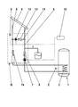
- the drawing represents an embodiment of the innovation and shows in a single figure schematically a solar system.
- the solar system for hot water and / or heating support consists of a memory 1, shown here as a hot water tank, with a temperature sensor 2 for detecting the storage temperature, a heat exchanger 3 for heating the memory 1, a solar circuit via a solar collector 4 with flow line 5 and return line 6, a circulation pump 7 for a heat transfer medium in the return line 6, one of these circulation pump 7 downstream non-return valve 8, a temperature sensor 9 for detecting the flow temperature in the solar circuit and a control device 10th
- a bypass line 11 with a further circulating pump 12 and a further non-return valve 13 is provided between the supply line 5 and the return line 6 of the solar circuit.
- a further check valve 14 is arranged, which prevents a backflow from the collector remote line region of the flow line 5 during operation of the further circulating pump 12 in the bypass line 11.
- bypass line 11 with the further circulating pump 12, the at least one non-return valve 8, 13, 14 and the temperature sensor 9 for detecting the flow temperature in the solar circuit together with the other hydraulic and control components can be summarized.
Landscapes
- Engineering & Computer Science (AREA)
- Physics & Mathematics (AREA)
- Thermal Sciences (AREA)
- Chemical & Material Sciences (AREA)
- Combustion & Propulsion (AREA)
- Mechanical Engineering (AREA)
- General Engineering & Computer Science (AREA)
- Life Sciences & Earth Sciences (AREA)
- Sustainable Development (AREA)
- Sustainable Energy (AREA)
- Heat-Pump Type And Storage Water Heaters (AREA)
Priority Applications (1)
| Application Number | Priority Date | Filing Date | Title |
|---|---|---|---|
| EP11176028A EP2551604A1 (fr) | 2011-07-29 | 2011-07-29 | Installation solaire |
Applications Claiming Priority (1)
| Application Number | Priority Date | Filing Date | Title |
|---|---|---|---|
| EP11176028A EP2551604A1 (fr) | 2011-07-29 | 2011-07-29 | Installation solaire |
Publications (1)
| Publication Number | Publication Date |
|---|---|
| EP2551604A1 true EP2551604A1 (fr) | 2013-01-30 |
Family
ID=44658614
Family Applications (1)
| Application Number | Title | Priority Date | Filing Date |
|---|---|---|---|
| EP11176028A Withdrawn EP2551604A1 (fr) | 2011-07-29 | 2011-07-29 | Installation solaire |
Country Status (1)
| Country | Link |
|---|---|
| EP (1) | EP2551604A1 (fr) |
Cited By (3)
| Publication number | Priority date | Publication date | Assignee | Title |
|---|---|---|---|---|
| CN103216880A (zh) * | 2013-04-28 | 2013-07-24 | 宁夏可可科技发展有限公司 | 太阳能供暖装置 |
| CN103353140A (zh) * | 2013-07-26 | 2013-10-16 | 华东建筑设计研究院有限公司 | 一种太阳能热水供给系统及其控制方法 |
| CN113739239A (zh) * | 2021-08-26 | 2021-12-03 | 宁夏电投热力有限公司 | 一种智慧供热系统管控系统及控制方法 |
Citations (6)
| Publication number | Priority date | Publication date | Assignee | Title |
|---|---|---|---|---|
| JPS5850A (ja) * | 1981-06-22 | 1983-01-05 | Matsushita Electric Ind Co Ltd | 太陽熱集熱制御装置 |
| JPS588946A (ja) * | 1981-07-06 | 1983-01-19 | Matsushita Electric Ind Co Ltd | 太陽熱集熱装置 |
| JPS58133565A (ja) * | 1982-02-02 | 1983-08-09 | Matsushita Electric Ind Co Ltd | 強制循環式ソ−ラシステム |
| JPS59200158A (ja) * | 1983-04-26 | 1984-11-13 | Matsushita Electric Ind Co Ltd | 太陽熱集熱装置 |
| EP2009359A2 (fr) * | 2007-06-29 | 2008-12-31 | Vaillant GmbH | Installation thermique solaire et procédé de fonctionnement d'une telle installation |
| EP2306116A1 (fr) * | 2009-10-01 | 2011-04-06 | European Solar Engineering SA | Circuit primaire hermétique pour système solaire thermique |
-
2011
- 2011-07-29 EP EP11176028A patent/EP2551604A1/fr not_active Withdrawn
Patent Citations (7)
| Publication number | Priority date | Publication date | Assignee | Title |
|---|---|---|---|---|
| JPS5850A (ja) * | 1981-06-22 | 1983-01-05 | Matsushita Electric Ind Co Ltd | 太陽熱集熱制御装置 |
| JPS588946A (ja) * | 1981-07-06 | 1983-01-19 | Matsushita Electric Ind Co Ltd | 太陽熱集熱装置 |
| JPS58133565A (ja) * | 1982-02-02 | 1983-08-09 | Matsushita Electric Ind Co Ltd | 強制循環式ソ−ラシステム |
| JPS59200158A (ja) * | 1983-04-26 | 1984-11-13 | Matsushita Electric Ind Co Ltd | 太陽熱集熱装置 |
| EP2009359A2 (fr) * | 2007-06-29 | 2008-12-31 | Vaillant GmbH | Installation thermique solaire et procédé de fonctionnement d'une telle installation |
| DE102008029527A1 (de) | 2007-06-29 | 2009-01-02 | Vaillant Gmbh | Solarthermische Anlage und Verfahren zum Betrieb einer solchen Anlage |
| EP2306116A1 (fr) * | 2009-10-01 | 2011-04-06 | European Solar Engineering SA | Circuit primaire hermétique pour système solaire thermique |
Cited By (4)
| Publication number | Priority date | Publication date | Assignee | Title |
|---|---|---|---|---|
| CN103216880A (zh) * | 2013-04-28 | 2013-07-24 | 宁夏可可科技发展有限公司 | 太阳能供暖装置 |
| CN103353140A (zh) * | 2013-07-26 | 2013-10-16 | 华东建筑设计研究院有限公司 | 一种太阳能热水供给系统及其控制方法 |
| CN113739239A (zh) * | 2021-08-26 | 2021-12-03 | 宁夏电投热力有限公司 | 一种智慧供热系统管控系统及控制方法 |
| CN113739239B (zh) * | 2021-08-26 | 2023-01-10 | 宁夏电投热力有限公司 | 一种智慧供热系统管控系统及控制方法 |
Similar Documents
| Publication | Publication Date | Title |
|---|---|---|
| EP2806168B1 (fr) | Module de pompe de circulation et installation thermosolaire le comprenant | |
| DE202013104746U1 (de) | Tankcontainer | |
| EP2009359B1 (fr) | procédé de fonctionnement d'une installation thermique solaire | |
| DE102008057495A1 (de) | Wärmespeicheranordnung | |
| EP1936298B1 (fr) | Dispositif de protection de siphon contre le gel | |
| DE102009006722B4 (de) | Solarheizanlage, Verfahren und Vorrichtung zur Diagnose einer Luftmenge in einem mit einem Solarfluid befüllten Solarfluidkreis und zum Betreiben einer Solarheizanlage | |
| DE202007018564U1 (de) | Heizungs- und/oder Warmwasserbereitungssystem | |
| EP2604946A2 (fr) | Accumulateur d'eau chaude avec réglage de la température de préparation sur la base d'informations de débit | |
| DE202010010743U1 (de) | Solaranlage | |
| DE10243170A1 (de) | Heizungsanlage mit einer Wärmepumpe mit Kältemittelverflüssiger | |
| DE102005035821B3 (de) | Thermische Solaranlage | |
| DE69105742T2 (de) | Zentralheizungsanlage. | |
| DE10254889B4 (de) | Regeltechnische Lösung für eine Wassererwärmungsanlage | |
| EP2682682B1 (fr) | Procédé de fonctionnement d'un dispositif de production d'eau chaude sanitaire | |
| EP2405205B1 (fr) | Séparateur de gaz dans une installation solaire pour la production de chaleur | |
| DE102008020637A1 (de) | Warmwasserversorgungsanlage mit einem Warmwasserspeicher | |
| WO2011012608A1 (fr) | Installation solaire pour la production d'eau chaude | |
| EP1619446B1 (fr) | Procédé pour réguler un circuit d'eau chaude | |
| DE3043123C2 (de) | Heizungsanlage mit einer Wärmepumpe | |
| EP3377770B1 (fr) | Pompe, système d'eau sanitaire, procédé de fonctionnement d'un système d'eau sanitaire et procédé d'autoapprentissage de la pompe dans le système d'eau sanitaire | |
| EP2213951A2 (fr) | Installation de chauffage solaire, procédé et dispositif de prolongement de la durée de fonctionnement d'une installation dotée d'un circuit de fluide fermé | |
| EP2851629B1 (fr) | Système de chauffage | |
| EP2463593A1 (fr) | Procédé de opération d'une installation de chauffage | |
| DE10062208A1 (de) | Gefrierschutz für Wasserleitungen | |
| DE102021006557A1 (de) | Verfahren zum Betrieb einer Wärmepumpenanlage |
Legal Events
| Date | Code | Title | Description |
|---|---|---|---|
| PUAI | Public reference made under article 153(3) epc to a published international application that has entered the european phase |
Free format text: ORIGINAL CODE: 0009012 |
|
| AK | Designated contracting states |
Kind code of ref document: A1 Designated state(s): AL AT BE BG CH CY CZ DE DK EE ES FI FR GB GR HR HU IE IS IT LI LT LU LV MC MK MT NL NO PL PT RO RS SE SI SK SM TR |
|
| AX | Request for extension of the european patent |
Extension state: BA ME |
|
| 17P | Request for examination filed |
Effective date: 20130730 |
|
| RBV | Designated contracting states (corrected) |
Designated state(s): AL AT BE BG CH CY CZ DE DK EE ES FI FR GB GR HR HU IE IS IT LI LT LU LV MC MK MT NL NO PL PT RO RS SE SI SK SM TR |
|
| GRAP | Despatch of communication of intention to grant a patent |
Free format text: ORIGINAL CODE: EPIDOSNIGR1 |
|
| RIC1 | Information provided on ipc code assigned before grant |
Ipc: F24D 11/00 20060101AFI20150220BHEP Ipc: F24D 17/00 20060101ALI20150220BHEP Ipc: F24D 19/10 20060101ALI20150220BHEP |
|
| INTG | Intention to grant announced |
Effective date: 20150313 |
|
| STAA | Information on the status of an ep patent application or granted ep patent |
Free format text: STATUS: THE APPLICATION IS DEEMED TO BE WITHDRAWN |
|
| 18D | Application deemed to be withdrawn |
Effective date: 20150724 |