EP2009391A1 - Pneumatischer Sensor mit erhöhter Druckempfindlichkeit durch Düsenoberflächenrauhigkeit - Google Patents
Pneumatischer Sensor mit erhöhter Druckempfindlichkeit durch Düsenoberflächenrauhigkeit Download PDFInfo
- Publication number
- EP2009391A1 EP2009391A1 EP08159163A EP08159163A EP2009391A1 EP 2009391 A1 EP2009391 A1 EP 2009391A1 EP 08159163 A EP08159163 A EP 08159163A EP 08159163 A EP08159163 A EP 08159163A EP 2009391 A1 EP2009391 A1 EP 2009391A1
- Authority
- EP
- European Patent Office
- Prior art keywords
- nozzle
- gas
- flow
- output face
- air gauge
- Prior art date
- Legal status (The legal status is an assumption and is not a legal conclusion. Google has not performed a legal analysis and makes no representation as to the accuracy of the status listed.)
- Granted
Links
- 230000035945 sensitivity Effects 0.000 title description 6
- 230000003746 surface roughness Effects 0.000 title description 2
- 238000000034 method Methods 0.000 claims description 11
- 230000002238 attenuated effect Effects 0.000 abstract description 5
- 238000005259 measurement Methods 0.000 description 52
- 235000019592 roughness Nutrition 0.000 description 17
- 230000008859 change Effects 0.000 description 10
- 235000012431 wafers Nutrition 0.000 description 9
- 230000000694 effects Effects 0.000 description 7
- 239000000463 material Substances 0.000 description 6
- 239000004065 semiconductor Substances 0.000 description 6
- 230000007423 decrease Effects 0.000 description 5
- 238000001459 lithography Methods 0.000 description 5
- XUIMIQQOPSSXEZ-UHFFFAOYSA-N Silicon Chemical compound [Si] XUIMIQQOPSSXEZ-UHFFFAOYSA-N 0.000 description 4
- 238000004519 manufacturing process Methods 0.000 description 4
- 230000010349 pulsation Effects 0.000 description 4
- 229910052710 silicon Inorganic materials 0.000 description 4
- 239000010703 silicon Substances 0.000 description 4
- 239000000758 substrate Substances 0.000 description 4
- 230000000875 corresponding effect Effects 0.000 description 3
- 230000001419 dependent effect Effects 0.000 description 3
- 238000010586 diagram Methods 0.000 description 3
- 230000006872 improvement Effects 0.000 description 3
- 229910052751 metal Inorganic materials 0.000 description 3
- 239000002184 metal Substances 0.000 description 3
- 230000003287 optical effect Effects 0.000 description 3
- 230000007704 transition Effects 0.000 description 3
- 230000005534 acoustic noise Effects 0.000 description 2
- 230000008901 benefit Effects 0.000 description 2
- 239000011248 coating agent Substances 0.000 description 2
- 238000000576 coating method Methods 0.000 description 2
- 238000012937 correction Methods 0.000 description 2
- 238000009826 distribution Methods 0.000 description 2
- 238000003754 machining Methods 0.000 description 2
- 230000000704 physical effect Effects 0.000 description 2
- 238000007788 roughening Methods 0.000 description 2
- 239000000523 sample Substances 0.000 description 2
- 239000004576 sand Substances 0.000 description 2
- 238000004513 sizing Methods 0.000 description 2
- 238000011144 upstream manufacturing Methods 0.000 description 2
- JBRZTFJDHDCESZ-UHFFFAOYSA-N AsGa Chemical compound [As]#[Ga] JBRZTFJDHDCESZ-UHFFFAOYSA-N 0.000 description 1
- GPXJNWSHGFTCBW-UHFFFAOYSA-N Indium phosphide Chemical compound [In]#P GPXJNWSHGFTCBW-UHFFFAOYSA-N 0.000 description 1
- 229910001374 Invar Inorganic materials 0.000 description 1
- 238000005422 blasting Methods 0.000 description 1
- 238000009530 blood pressure measurement Methods 0.000 description 1
- 239000000356 contaminant Substances 0.000 description 1
- 230000002596 correlated effect Effects 0.000 description 1
- 238000005530 etching Methods 0.000 description 1
- 238000002474 experimental method Methods 0.000 description 1
- 238000010285 flame spraying Methods 0.000 description 1
- 239000012530 fluid Substances 0.000 description 1
- 239000011521 glass Substances 0.000 description 1
- UGKDIUIOSMUOAW-UHFFFAOYSA-N iron nickel Chemical compound [Fe].[Ni] UGKDIUIOSMUOAW-UHFFFAOYSA-N 0.000 description 1
- 230000001788 irregular Effects 0.000 description 1
- 238000012986 modification Methods 0.000 description 1
- 230000004048 modification Effects 0.000 description 1
- 230000009467 reduction Effects 0.000 description 1
- 230000011664 signaling Effects 0.000 description 1
- 230000001960 triggered effect Effects 0.000 description 1
- 230000000007 visual effect Effects 0.000 description 1
Images


Classifications
-
- G—PHYSICS
- G01—MEASURING; TESTING
- G01B—MEASURING LENGTH, THICKNESS OR SIMILAR LINEAR DIMENSIONS; MEASURING ANGLES; MEASURING AREAS; MEASURING IRREGULARITIES OF SURFACES OR CONTOURS
- G01B13/00—Measuring arrangements characterised by the use of fluids
- G01B13/12—Measuring arrangements characterised by the use of fluids for measuring distance or clearance between spaced objects or spaced apertures
-
- D—TEXTILES; PAPER
- D06—TREATMENT OF TEXTILES OR THE LIKE; LAUNDERING; FLEXIBLE MATERIALS NOT OTHERWISE PROVIDED FOR
- D06C—FINISHING, DRESSING, TENTERING OR STRETCHING TEXTILE FABRICS
- D06C13/00—Shearing, clipping or cropping surfaces of textile fabrics; Pile cutting; Trimming seamed edges
-
- G—PHYSICS
- G01—MEASURING; TESTING
- G01B—MEASURING LENGTH, THICKNESS OR SIMILAR LINEAR DIMENSIONS; MEASURING ANGLES; MEASURING AREAS; MEASURING IRREGULARITIES OF SURFACES OR CONTOURS
- G01B13/00—Measuring arrangements characterised by the use of fluids
- G01B13/02—Measuring arrangements characterised by the use of fluids for measuring length, width or thickness
Definitions
- the present invention relates to an apparatus and method for detecting very small distances, and more particularly to proximity sensing.
- the challenges associated with creating a proximity sensor of such accuracy are significant, particularly in the context of lithography systems.
- the proximity sensor in addition to being non-intrusive and having the ability to precisely detect very small distances, the proximity sensor can not introduce contaminants, cause minute temperature changes, or come in contact with the work-surface, typically a semiconductor wafer. Occurrence of either situation may significantly degrade or ruin the semiconductor quality.
- proximity sensors include capacitance and optical gauges. These proximity sensors have serious shortcomings when used in lithography systems because physical properties of materials deposited on wafers may impact the precision of these devices. For example, capacitance gauges, being dependent on the concentration of electric charges, can yield spurious proximity readings in locations where one type of material (e.g., metal) is concentrated.
- Another class of problems occurs when exotic wafers are made of or contain deposits of non-conductive and/or photosensitive materials, such as Gallium Arsenide (GaAs) and Indium Phosphide (InP). In these cases, capacitance and optical gauges may provide spurious results.
- GaAs Gallium Arsenide
- InP Indium Phosphide
- Air gauge sensors typically emit a dehydrated, filtered air flow onto a surface (e.g., the silicon wafer) and then measure its back pressure to determine distance between the measurement nozzle and that surface. More sensitive air gauge sensors use both reference and measurement nozzles emitting an air flow onto reference and measurement surfaces to determine surface distances.
- An air gauge sensor is not vulnerable to concentrations of electric charges nor electrical, optical and other physical properties of the wafer's surface.
- Current semiconductor manufacturing techniques require that proximity is gauged with high precision of the order of nanometers.
- Earlier versions of air gauge sensors unfortunately, often do not meet today's lithography requirements for precision. Today's requirements for nanometer repeatability and registration accuracy are more stringent than what is currently available in the industry at large. Additionally, earlier devices do not meet today's needs for dimensional stability throughout specific temperature ranges.
- a gas gauge according to an embodiment of the present invention operates with a flow rate that corresponds to flows in the transitional region between laminar and turbulent flow.
- the transitional region includes flows having a Reynold's number between approximately 2100 and 5100.
- the pressure drop across the surface of the nozzle face increases as the friction factor of that surface increases with increasing Reynold's number.
- Surface friction factor values are based on two surfaces, the nozzle face and the measurement surface. While the silicon wafer measurement surface cannot be interfered with, the nozzle face surface may be roughened to effectively increase the friction factor across the nozzle surface.
- the surface may be roughened, for example and without limitation, by shot-blasting the nozzle face to various "sand roughnesses;" flame-spraying a rough oxide coating on the nozzle face; machining circular, concentric rings into or protruding out of the nozzle face; machining numerous, small hemispherical depressions either into or out of the nozzle face while staggering their arrangement; and/or introducing dozens of staggered pins into the nozzle face.
- the nozzle face surface area and its roughness is important in dealing with the pressure drop of an air gauge within the transitional flow regime.
- Noise generated by the increased flow rate may be attenuated by using one or more Helmholtz attenuators.
- FIG. 1 is a functional diagram of a gas gauge proximity sensor.
- FIG. 2 is a cross-sectional diagram of a nozzle in a gas proximity sensor.
- FIG. 3 is a graph illustrating Reynold's number versus friction factor that identifies the four flow regimes, namely laminar, critical, transitional, and turbulent, and the effect of surface "relative roughness" upon each regime.
- FIG. 4 illustrates the radial variation of Reynold's number across a nozzle face for various gas flow rates.
- FIG. 5 illustrates the theoretical amount of gain (relative pressure drop per gap-height change) available for a gas gauge nozzle according to an embodiment of the present invention.
- FIG. 6 is a cross-section of a nozzle having saw-tooth cuts according to an embodiment of the present invention.
- FIG. 7A is a cross-section of a nozzle having hemispherical protrusions according to an embodiment of the present invention.
- FIG. 7B is a surface view of a nozzle having hemispherical depressions according to an embodiment of the present invention.
- FIG. 8 illustrates a nozzle having a Helmholtz attenuator according to an embodiment of the present invention.
- FIG. 9 is a flowchart of a method of sensing distance to an object according to an embodiment of the present invention.
- FIG. 1 provides a diagram of gas gauge proximity sensor 100.
- Gas gauge proximity sensor 100 is one type of proximity sensor that can be improved through use of one or more embodiments of the present invention, and is not intended to limit the scope of the invention.
- Gas gauge proximity sensor 100 includes gas pressure regulator 105, mass flow controller 106, central channel 112, measurement channel 116, reference channel 118, snubber 120, snubber 122, measurement probe 128, reference probe 130, bridge channel 136 and mass flow sensor 138.
- Gas supply 102 injects gas at a desired pressure into gas gauge proximity sensor 100.
- Central channel 112 connects gas supply 102 to gas pressure regulator 105 and mass flow controller 106 and then terminates at junction 114.
- Gas pressure regulator 105 and mass flow controller 106 maintains a constant flow rate within gas gauge proximity sensor 100.
- Gas is forced out from mass flow controller 106 into channel 112 with an accumulator 108 affixed to channel 112.
- a snubber can be placed between mass flow controller 106 and junction 114.
- Sensor 100 has two snubbers 120 and 122, placed at each leg of the flow split at junction 114.
- a snubber reduces gas turbulence and consequent noise introduced by the gas supply 102, and also acts as a resistive element.
- other types of resistive elements such as orifices can be used, although orifices will not reduce turbulence.
- mass flow controller 106 Upon exiting mass flow controller 106, gas travels through central channel 112 to junction 114. Central channel 112 terminates at junction 114 and divides into measurement channel 116 and reference channel 118. Mass flow controller 106 injects gas at a sufficiently low rate to provide laminar and incompressible fluid flow throughout the system which minimizes the production of undesired pneumatic noise. Likewise, the system geometry can be appropriately sized to maintain the laminar flow characteristics established by mass flow controller 106.
- Bridge channel 136 is coupled between measurement channel 116 and reference channel 118. Bridge channel 136 connects to measurement channel 116 at junction 124. Bridge channel 136 connects to reference channel 118 at junction 126. In one example, the distance between junction 114 and junction 124 and the distance between junction 114 and junction 126 are equal, which helps flow symmetry and gas gauge performance.
- Channels 112, 116, 118, and 136 can be made up of conduits (tubes, pipes, etc.) or any other type of structure that can contain and guide gas flow through sensor 100. It is desirable that the channels do not have sharp bends, irregularities or unnecessary obstructions that may introduce pneumatic noise, for example, by producing local turbulence or flow instability.
- the overall lengths of measurement channel 116 and reference channel 118 can be equal or in other examples can be unequal. However, the lack of symmetry may hinder the performance of sensor 100 and require additional flow correction factors.
- Reference channel 118 terminates into reference nozzle 130.
- measurement channel 116 terminates into measurement nozzle 128.
- Reference nozzle 130 is positioned above reference surface 134.
- Measurement nozzle 128 is positioned above measurement surface 132.
- measurement surface 132 is often a substrate, semiconductor wafer, stage supporting a wafer, flat panel display, glass substrate, a print head, a micro- or nano-fluidic device or the like.
- Reference surface 134 can be a flat metal plate, but is not limited to this example.
- Gas injected by gas supply 102 is emitted from each of the nozzles 128, 130 and impinges upon measurement surface 132 and reference surface 134. As stated above, the distance between a nozzle and a corresponding measurement or reference surface is referred to as a standoff.
- reference nozzle 130 is positioned above a fixed reference surface 134 with a known reference standoff 142.
- Measurement nozzle 128 is positioned above measurement surface 132 with an unknown measurement standoff 140.
- the known reference standoff 142 is set to a desired constant value representing an optimum standoff.
- the backpressure upstream of the measurement nozzle 128 is a function of the unknown measurement standoff 140; and the backpressure upstream of the reference nozzle 130 is a function of the known reference standoff 142. If standoffs 140 and 142 are equal, the configuration is symmetrical and the bridge is balanced. Consequently, there is no gas flow through bridging channel 136.
- the measurement standoff 140 and reference standoff 142 are different, the resulting pressure difference between the measurement channel 116 and the reference channel 118 induces a flow of gas through mass flow sensor 138.
- Mass flow sensor 138 is located along bridge channel 136, for example, at a central location. Mass flow sensor 136 senses gas flows induced by pressure differences between measurement channel 116 and reference channel 118. These pressure differences occur as a result of changes in the vertical positioning of measurement surface 132. For a symmetric bridge, when measurement standoff 140 and reference standoff 142 are equal, the standoff is the same for both of the nozzles 128, 130 compared to surfaces 132, 134. Mass flow sensor 138 will detect no mass flow, since there will be no pressure difference between the measurement and reference channels. Differences between measurement standoff 140 and reference standoff 142 will lead to different pressures in measurement channel 116 and reference channel 118. Proper offsets can be introduced for an asymmetric arrangement.
- Mass flow sensor 138 senses gas flow induced by a pressure difference or imbalance.
- a pressure difference causes a gas flow, the rate of which is a unique function of the measurement standoff 140.
- the difference between gas pressures in the measurement channel 116 and the reference channel 118 is a function of the difference between the magnitudes of standoffs 140 and 142. If reference standoff 142 is set to a known standoff, the difference between gas pressures in the measurement channel 116 and the reference channel 118 is a function of the size of measurement standoff 140 (that is, the unknown standoff between measurement surface 132 and measurement nozzle 128).
- Mass flow sensor 138 detects gas flow in either direction through bridge channel 136. Because of the bridge configuration, gas flow occurs through bridge channel 136 only when pressure differences between channels 116, 118 occur. When a pressure imbalance exists, mass flow sensor 138 detects a resulting gas flow, and can initiate an appropriate control function. Mass flow sensor 138 can provide an indication of a sensed flow through a visual display, audio indication, computer controlled system or other signaling means. Alternatively, in place of a mass flow sensor, a differential pressure sensor may be used. The differential pressure sensor measures the difference in pressure between the two channels, which is a function of the difference between the measurement and reference standoffs.
- Proximity sensor 100 is provided as one example of a device with a nozzle that can benefit from one or more embodiments of the present invention. These exemplary embodiments of the present invention are not intended to be limited to use with only proximity sensor 100. Rather the exemplary embodiments of the present invention can be used to improve other types of proximity sensors.
- FIG. 2 is an illustration providing further detail of an exemplary measurement nozzle 202.
- Nozzle 202 may be similar to, for example, measurement nozzle 128 of FIG. 1 .
- nozzle 202 is proximate to an object or measurement surface 204.
- Nozzle 202 has a nozzle face 206 that is substantially parallel to surface 204.
- Nozzle face 206 is separated from surface 204 by a distance 208.
- Gas typically flows out of the nozzle in the z direction through an orifice 210, and then radially outward between nozzle face 206 and surface 204. The pressure drop of the gas across nozzle face 206 is indicative of the height of distance 208.
- the distance between a measurement nozzle and a measurement surface may be determined by outputting a gas stream at a steady rate and measuring the pressure drop (also referred to as the backpressure) of the gas stream across nozzle face 206.
- the pressure drop also referred to as the backpressure
- the correlation between the local pressure drop and the gap height is increased.
- the pressure drop can be related to a friction factor of the nozzle face times the radial length of the nozzle face.
- Re ⁇ ⁇ VD ⁇
- ⁇ the density of the gas
- V the radial velocity of the gas over the nozzle face
- D the local characteristic dimension of the flow (which in a gas gauge nozzle is the diameter of the nozzle defined by the complex geometric relationship of Eq. 2)
- ⁇ the viscosity of the gas.
- FIG. 3 is a logarithmic graph illustrating Reynold's number on the horizontal axis and friction factor on the vertical axis.
- FIG. 3 is commonly referred to as a "Moody plot.” Further description of the Moody plot may be found in, for example, L.F. Moody, "Friction Factors for Pipe Flow,” ASME Trans., vol. 66, pp. 671-684, 1944 , which is incorporated by reference herein in its entirety.
- Previous gas gauges operated at flow rates having a Reynold's number of approximately 200-300. As illustrated in FIG. 3 , such a flow rate is in the laminar flow region.
- the laminar flow region is defined by curve 302.
- gas flow rates begin to change from the laminar flow region into a transitional flow region.
- the transitional flow region is defined by curve 304.
- the flow rates begin to switch to a fully turbulent region, defined by curve 306.
- Increasing the Reynold's number is typically avoided when operating in the laminar flow regime, as it decreases the friction factor of the nozzle, and thereby decreases the gain available from the gauge.
- the friction factor begins to increase as the Reynold's number increases.
- the flowfield of a nozzle operating in the transitional region is opposite in frictional performance to that of traditional nozzles operating in a laminar flow region, where the friction factor slowly decreases with increasing Reynold's number.
- the sensitivity of this frictional decrease is measured by the differences in slopes between curves 302 and 304 of FIG. 3 .
- the change from the laminar flow region to the transitional flow region physically implies a channel flow undergoing a velocity profile change.
- the velocity profile changes from a parabolic velocity distribution to a modified, truncated hyperbolic velocity distribution. Friction within the transitional flow region influences nozzle flow pressure drops since the friction factor changes most dramatically within this zone, as seen by the positive steepness of the slope of curve 304. An increase in Reynold's number thereby results in a sensitivity increase in relating pressure drop to nozzle distances from the plate, yielding a more responsive relative gain with gap height measurements.
- the Reynold's number is dependent on the density of the gas used, the radial velocity of the gas over the nozzle face, the complex characteristic diameter of the nozzle, and the viscosity of the gas used. If the same gas (such as, for example, air) is used in the transitional flow nozzle as was used in the laminar flow nozzle, the density and viscosity of the gas cannot be changed.
- the only way to increase the Reynold's number is to either increase the velocity of the gas through the nozzle or to increase the characteristic diameter of the nozzle.
- the Reynold's number is increased in an embodiment of the present invention by increasing the velocity (also referred to as the flow rate) of the gas through the nozzle.
- a traditional laminar flow gauge typically exhibits a volumetric gas flow rate of approximately 1000 sccm (standard cubic centimeters per minute).
- Increasing the Reynold's number to a transitional flow regime having a Reynold's number of approximately 2100 while varying only the flow rate results in a flow rate of approximately 6800 sccm.
- FIG. 4 illustrates an exemplary change in Reynold's number at various positions extending radially outward from orifice 210 across nozzle face 206 in FIG. 2 for different gas flow rates.
- the radial position of the measurement in mm is illustrated on the horizontal axis, while the Reynold's number for gas flow in the gap between the nozzle face and the measurement surface is illustrated on the vertical axis.
- the change in Reynold's number as the radial position increases is indicative of two events: 1) the change in pressure drop of the gas across the nozzle surface due to the local friction factor changing with local Reynold's number, and 2) the constant change in the local characteristic dimension ( D ) of the flow as it moves radially outward.
- Curve 402 illustrates the pressure drop for a traditional laminar flow nozzle (e.g., flow rate of approximately 1000 sccm). The Reynold's number for curve 402 is between approximately 230 and approximately 625.
- Curve 404 illustrates the pressure drop for a transitional flow nozzle at a lower flow rate (e.g., flow rate of approximately 6800 sccm). The average Reynold's number for curve 404 is approximately 2900.
- Curve 406 illustrates the pressure drop for a transitional flow nozzle at a higher flow rate (e.g., flow rate of approximately 9000 sccm). The average Reynold's number for curve 406 is approximately 3900.
- the pressure drop across the nozzle face is greatest for curve 406. Because the pressure drop is greater, the transitional flow nozzle operating at a higher flow rate is more sensitive to small changes in pressure than a transitional flow nozzle operating at a lower flow rate, which is still more sensitive to pressure changes than a laminar flow nozzle.
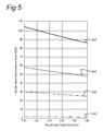
- FIG. 5 illustrates a theoretical amount of gain available within a transitional versus laminar friction factor regime according to nozzle operation.
- Gain is determined by finding the local slope of a given curve of pressure drop versus gap height calculated at 135 microns. The nozzle cap height in microns is illustrated on the horizontal axis, while the total pressure drop in kPA across the nozzle face is illustrated on the vertical axis.
- Curve 502 illustrates a theoretical gain of a laminar flow nozzle operating at a flow rate of approximately 1000 sccm. The gain of curve 502 is approximately 0.024 kPa/micron.
- Curve 504 illustrates a theoretical gain of a transitional flow nozzle having a relative roughness of approximately 10 -6 (e.g., a smooth surface) operating at a lower flow rate of approximately 4900 sccm.
- the gain of curve 504 is approximately 0.512 kPa/micron.
- Curve 506 illustrates a theoretical gain of a transitional flow nozzle having a relative roughness of approximately 10 -6 operating at a higher flow rate of approximately 6800 sccm.
- the gain of curve 506 is approximately .983 kPa/micron.
- Curve 508 illustrates a theoretical gain of a transitional flow nozzle having a relative roughness of approximately 0.05 operating at a higher flow rate of approximately 9000 sccm.
- the gain of curve 508 is approximately 1.759 kPa/micron.
- a theoretical improvement in gain from about 0.024 to about 0.512 kPa/micron (a gain of about 21X) can be achieved by transitioning from a laminar flow rate (e.g., curve 502) to a low transitional flow rate system (e.g., curve 504).
- a theoretical improvement in nozzle gain from about 0.512 to about 0.983 kPa/micron (an overall gain of about 41X), and even to about 1.759 kPa/micron (for an overall gain of about 73X) can be achieved by transitioning from a laminar flow rate (e.g., curve 502) to a high transitional flow rate (e.g., curve 506 and curve 508, respectively).
- FIG. 5 illustrates the gain in terms of absolute gains
- the relative gain may also be determined by theoretically treating the flow as if it were always laminar. To determine this relative gain, the isolated instance of increasing the nozzle flow rate and corresponding pressure drop is evaluated strictly using the laminar flow correlation, without considering the actual physics of the existence of a transitional region. Such results indicate the strict relative gains from flowing at a rate of approximately 6800 sccm (as compared to approximately 1000 sccm) and using the original laminar friction factor of curve 302 in FIG. 3 , extrapolated to a Reynold's number of about 2900. This produces a relative gain of about 0.82 kPa/micron (a gain of about 39X).
- Previous gas gauges operated at a laminar flow rate having a Reynold's number of approximately 200-300. At such Reynold's numbers and up to a Reynold's number of about 2100, surface relative-roughness of the nozzle face (RR) has virtually no effect on the pressure drop. Relative-roughness is defined as the ratio of the height of repeatable surface irregularities to the hydraulic diameter of the nozzle geometry and gap height combination as shown in Eq. 2. At Reynold's numbers in the transitional flow regime (2100 ⁇ Re ⁇ 5100), however, the friction factor of the nozzle, which is correlated to the gain of the gauge, is a variable depending upon the roughness of the nozzle-face surface. As indicated by curves 308 in FIG.
- FIG. 5 illustrates the theoretical gain of the nozzle available in a transitional flow regime.
- curve 506 illustrates the gain of a transitional flow nozzle at a higher flow rate
- the gain is based on a nozzle having a relatively smooth surface.
- Curve 508 illustrates the theoretical gain of a transitional flow nozzle whose surface has been roughened, when the nozzle is operated at a higher flow rate.
- the nozzle face may be roughened by adding specific surface irregularities to it.
- the surface irregularities may be, for example, nano- or micro-irregularities. There are various ways to roughen the nozzle surface.
- the nozzle-face may be shot-blasted to various equivalent "sand roughnesses" to a level defined by a Moody plot for flow resistances, such as FIG. 3 .
- a rough oxide coating may be flame-sprayed on the nozzle face.
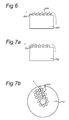
- the nozzle face may be machined into various configurations.
- circular, concentric rings are machined either into or protruding out of the nozzle face.
- FIG. 6 is a cross-section of exemplary nozzle face 602. As illustrated in FIG. 6 , rings 604 may be, for example, saw-tooth cuts. The flow of gas 606 across nozzle face 602 is inhibited due to the increased friction factor and flow rate in the transitional flow region.
- FIG. 7A illustrates another embodiment, in which numerous small, hemispherical depressions 704 are machined either into or out of nozzle face 702. To prevent flow channels from developing across nozzle face 702, the arrangement of depressions 704 across nozzle face 702 may be staggered.
- dozens of staggered pins may be introduced into the nozzle face by, for example, using silicon etching techniques to create an array of pins on a silicon chip that is then epoxied to the face of the nozzle.
- the pins may have a diameter of, for example, approximately 10 microns and a height of, for example, approximately 10 microns.
- Increasing the roughness of the nozzle surface also increases the possibility that the nozzle will receive false feedback or pushback from air interacting with the roughened surface.
- Such false feedback may be minimized by, for example, starting with a high roughness inside the nozzle face and transitioning the level of the roughness as the radial distance from the nozzle is increased.
- the reference nozzle may also be roughened so as to cancel out the effect of false feedback from the roughened measurement nozzle surface.
- the nozzle may be made from a material that is resistant to thermal expansion.
- An example material is a hybrid iron-nickel metal such as Invar.
- FIG. 9 is a flowchart of a method 900 for sensing a distance to an object from a nozzle, according to an embodiment of the present invention.
- Method 900 may be used, for example, with a gas gauge.
- the object is provided within a measuring range of the nozzle.
- the object may be, for example and without limitation, a substrate or semiconductor wafer surface.
- the surface of the nozzle facing the object may be roughened as described above.
- a gas is supplied in a space between the nozzle and the object.
- the gas may be, for example and without limitation, air.
- the gas is supplied in the space with a flow rate that corresponds to a Reynold's number flow in the transitional region between laminar flow and turbulent flow.
- noise generated by the supply of gas is attenuated.
- the noise may be attenuated, for example, as described below.
- step 908 a pressure drop across the nozzle face is sensed.
- the pressure drop is indicative of the distance to the substrate surface.
- the nozzle gap Reynold's number used in existing systems is approximately 200-300, with a nominal nozzle gap height of about 135 microns. Such a system requires an airflow of approximately 1000 sccm. Operation above a Reynold's number of approximately 2100 requires a flow rate of at least approximately 3400 sccm. Although the gain is theoretically increased when the nozzle is operated at such a high flow rate, the noise generated by such a high flow rate may disrupt the sensitivity of the nozzle unless the noise is abated.
- This noise may be attenuated by the muffling effect of the nozzle face surface irregularities.
- Nozzle pressure drop increases with increasing nozzle face roughness for a given transitional flowfield, since the local boundary layer buildup forms local recirculation zones which act to attenuate acoustic noise emanating from the nozzle throat. Acoustic noise emanating from the nozzle thus abates with increased flow rate.
- a nozzle operating at a laminar flow rate exhibits poor noise abatement compared to a nozzle operating at a transitional flow rate. Therefore, while previous, laminar flow nozzles exhibited poor noise abatement when the flow rate was increased, transitional flow nozzles do the opposite and aggressively abate noise through the introduction of roughened flow surfaces.
- Snubbers have been successfully used to attenuate noise. These systems force the flow through a labyrinth of irregular channels that cause a reduction in flow turbulence and its corresponding noise. Snubbers have been used in air gauges as, for example, snubbers 120 and 121 in FIG. 1 . Snubbers are very useful as noise attenuators when gauge flows exceed 1000 sccm. Their use at strategic flow turns and splits may increase during nozzle operation at increased flow to achieve a transitional flow regime with enhanced performance gain.
- the Helmholtz effect may also be used to act as a muffler in attenuating the noise from acoustic pressure pulses.
- Strategically-placed Helmholtz sound absorbing cavities (referred to herein as Helmholtz attenuators) may be used to attenuate unwanted nozzle noise.
- FIG. 8 illustrates a cross-section of a gas gauge nozzle 800 having Helmholtz attenuators 802 and 804.
- Helmholtz attenuators can be discrete, local cavities arranged parallel with the airflow and specifically designed to absorb unwanted acoustic frequencies.
- a Helmholtz attenuator such as attenuator 802 or 804, is essentially a cavity covered by a false working wall containing multiple perforations that allow pressure pulsations (that is, noise) to expand normal to the flow direction. The pressure pulsations are then trapped in the cavity, which absorbs the pulsations.
- FIG. 8 illustrates two regions of nozzle 800 where the introduction of a Helmholtz attenuator can dramatically attenuate pressure pulsation noises.
- Attenuator 802 is located inside the barrel of the nozzle, where upstream-generated noise is absorbed or muffled before the noise escapes the nozzle throat region.
- Attenuator 804 is located within the face of the nozzle to reduce noise from the gas passing through gap 806 and escaping nozzle 800. So that attenuators 802 and 804 do not interfere with the pressure measurement of the gas gauge, attenuators 802 and 804 are located at places in the nozzle that do not affect the friction factor.
- the surface of attenuator 804 (that is, the area between the holes in attenuator 804) may be roughened in accordance with the rest of the nozzle face.
- Arrows 808 and 810 illustrate the path of the gas exiting the nozzle in an outward direction.
- a Helmholtz attenuator can be tuned to a particular acoustic frequency by selecting specific geometric hole sizing, geometric hole spacing and cavity dimensions of the Helmholtz attenuator.
- the properties of a Helmholtz resonator e.g., hole sizing, hole spacing, cavity width, etc. are determined by the frequency of the noise to be abated.
- Some noise is useful for logic correction within feedback loops, such as noise caused by temperature fluctuations or noise caused by the electronics of the system, and should not be removed from the system. Other noise, such as noise caused by increased airflow, needs to be removed.
- the frequency band of noise to be removed is determined, the diameter of holes in the plate of the Helmholtz attenuator, the spacing of the holes, and the cavity depth are designed so as to remove noise at that frequency band. If multiple frequency bands are to be abated, multiple Helmholtz attenuators may be used. Alternatively, a single Helmholtz resonator having multiple compartments may be used, where each compartment is optimized for a given frequency band.
- the above described examples may also be embodied as method embodiments which use one of the air gauge alternatives, i.e. a method for sensing a distance to an object from a nozzle, comprising providing the object within a measuring range of the nozzle, and supplying a gas in a space between the nozzle and the object, wherein the gas is supplied in the space with a flow rate that corresponds to a flow in a transitional region between laminar and turbulent flow.
- Supplying a gas can comprise supplying the gas across an output face of the nozzle provided with an orifice for supplying the gas in the space.
- Supplying a gas can further comprise supplying the gas across a surface irregularity on the output face of the nozzle, wherein the surface irregularity increases a friction factor which increases a pressure drop along the output face in an outward direction from the orifice to an edge of the output face.
- Supplying a gas can further comprise supplying the gas across the output face of the air gauge nozzle, wherein the output face has concentric rings formed in the output face.
- Supplying a gas can further comprise supplying the gas across the output face of the air gauge nozzle, wherein the output face has concentric rings protruding out from the output face.
- Supplying a gas can further comprise supplying the gas across the output face of the air gauge nozzle, wherein the output face has at least one of a plurality of hemispherical depressions or a plurality of hemispherical protrusions on the output face.
- Supplying a gas can further comprise supplying the gas at a flow rate that corresponds to a local Reynold's number higher than at least one of approximately 2000 and 2100 between the output face and the object.
- Supplying a gas can further comprise supplying the gas at a flow rate that corresponds to a local Reynold's number lower than at least one of approximately 4200 and 5100 between the output face and the object.
- Supplying a gas can comprise supplying the gas across a washer formed with a set of surface irregularities added to a surface of the nozzle.
- the method can further comprise attenuating, in the nozzle, noise produced by an air gauge.
- Attenuating noise can comprise attenuating noise using a Helmholtz resonator located on an output face of the nozzle.
- Attenuating noise can further comprise attenuating noise using the combined use of at least one snubber placed at a strategic air gauge flow turn and a Helmholtz resonator located on the output face of the nozzle.
- Attenuating noise can further comprise attenuating noise using a Helmholtz resonator having a surface irregularity that increases a friction factor of a Helmholtz resonator surface.
- Attenuating noise can comprise attenuating noise using a Helmholtz resonator located on an inner wall of the nozzle.
- Supplying a gas can comprise supplying gas at a flow rate in a range of approximately 3400 standard cubic centimeters per minute to approximately 9000 standard cubic centimeters per minute.
- Supplying a gas can comprise supplying a gas flow sufficient to create a local Reynold's number between the nozzle face and the object that generates a transitional flow regime.
Landscapes
- Physics & Mathematics (AREA)
- General Physics & Mathematics (AREA)
- Engineering & Computer Science (AREA)
- Textile Engineering (AREA)
- Measuring Arrangements Characterized By The Use Of Fluids (AREA)
- Measuring Volume Flow (AREA)
- Measuring Fluid Pressure (AREA)
Applications Claiming Priority (1)
| Application Number | Priority Date | Filing Date | Title |
|---|---|---|---|
| US11/769,421 US7578168B2 (en) | 2007-06-27 | 2007-06-27 | Increasing gas gauge pressure sensitivity using nozzle-face surface roughness |
Publications (2)
| Publication Number | Publication Date |
|---|---|
| EP2009391A1 true EP2009391A1 (de) | 2008-12-31 |
| EP2009391B1 EP2009391B1 (de) | 2011-04-20 |
Family
ID=39705297
Family Applications (1)
| Application Number | Title | Priority Date | Filing Date |
|---|---|---|---|
| EP08159163A Not-in-force EP2009391B1 (de) | 2007-06-27 | 2008-06-27 | Pneumatischer Sensor mit erhöhter Druckempfindlichkeit durch Düsenoberflächenrauhigkeit |
Country Status (9)
| Country | Link |
|---|---|
| US (1) | US7578168B2 (de) |
| EP (1) | EP2009391B1 (de) |
| JP (1) | JP5155031B2 (de) |
| KR (1) | KR100994542B1 (de) |
| CN (1) | CN101334273B (de) |
| AT (1) | ATE506597T1 (de) |
| DE (1) | DE602008006298D1 (de) |
| SG (1) | SG148932A1 (de) |
| TW (1) | TWI385367B (de) |
Families Citing this family (8)
| Publication number | Priority date | Publication date | Assignee | Title |
|---|---|---|---|---|
| US20100206295A1 (en) * | 2009-02-03 | 2010-08-19 | Xiao Dong Xiang | Systems and methods of solar thermal concentration for 2-dimensional focusing concentrators including features of sequential heating, thermal loss reduction, and/or adjustment of operation or operating parameters |
| CN101586949B (zh) * | 2009-05-20 | 2012-10-17 | 大连现代辅机开发制造有限公司 | 定位销切换、检测方法及装置 |
| KR101321322B1 (ko) * | 2011-04-22 | 2013-10-23 | 시바우라 메카트로닉스 가부시끼가이샤 | 기판 반송 장치 및 반송 방법 |
| GB2509323B (en) * | 2012-12-28 | 2015-01-07 | Glide Talk Ltd | Reduced latency server-mediated audio-video communication |
| CN105352456A (zh) * | 2015-11-10 | 2016-02-24 | 常州市西夏墅企业创新发展中心 | 一种厚度测量装置 |
| JP6883325B2 (ja) * | 2017-08-09 | 2021-06-09 | アドバンス電気工業株式会社 | 液マイクロメータ |
| CN112771451B (zh) * | 2018-09-27 | 2024-05-07 | Asml荷兰有限公司 | 水平传感器和包括水平传感器的光刻设备 |
| CN112997117B (zh) | 2018-11-05 | 2024-12-17 | Asml控股股份有限公司 | 测量光刻设备中的图案形成装置的变形的设备和方法 |
Citations (2)
| Publication number | Priority date | Publication date | Assignee | Title |
|---|---|---|---|---|
| US5298073A (en) | 1992-02-28 | 1994-03-29 | Libbey-Owens-Ford Co. | Two sensor for determining spacing between surfaces |
| EP1431709A2 (de) | 2002-12-19 | 2004-06-23 | ASML Holding N.V. | Hochauflösender, mit Gasströmung betriebener Näherungssensor |
Family Cites Families (47)
| Publication number | Priority date | Publication date | Assignee | Title |
|---|---|---|---|---|
| US2276036A (en) * | 1940-11-23 | 1942-03-10 | Westinghouse Electric & Mfg Co | Pneumatic thickness gauge |
| NL73735C (de) * | 1949-06-30 | |||
| US2986924A (en) * | 1955-09-16 | 1961-06-06 | Becker Wilhelm Fritz Kurt | Device for location of surfaces |
| US3127764A (en) * | 1961-09-18 | 1964-04-07 | G P E Controls Inc | Concentric double aperture air nozzle |
| GB1094833A (en) * | 1965-09-24 | 1967-12-13 | Burchell James Gladwyn | Improvements in or relating to gauges |
| US3495442A (en) * | 1967-06-21 | 1970-02-17 | Pillsbury Co | Thickness measuring instrument |
| FR1577249A (de) * | 1967-12-06 | 1969-08-08 | ||
| US3597961A (en) * | 1968-07-26 | 1971-08-10 | Ite Imperial Corp | Fluid operated sensing device |
| US3545256A (en) * | 1969-02-10 | 1970-12-08 | Pitney Bowes Inc | High sensitivity fluidic proximity detector |
| SE331199B (de) * | 1970-03-11 | 1970-12-14 | Mecman Ab | |
| US3709027A (en) * | 1971-01-22 | 1973-01-09 | Automatic Switch Co | Proximity sensing device |
| US4059130A (en) * | 1973-09-14 | 1977-11-22 | Bailey Meter Company | Proximity sensor with zero adjustment |
| US3894552A (en) * | 1974-01-31 | 1975-07-15 | Foxboro Co | Transducer nozzle |
| US3942556A (en) * | 1974-09-30 | 1976-03-09 | Dana Corporation | Fluidic sensor |
| JPS5271826A (en) * | 1975-12-10 | 1977-06-15 | Saito Chiyuuji | Noise silencing shielding material |
| US4090406A (en) * | 1977-06-23 | 1978-05-23 | Rodder Jerome A | Sensor |
| US4142401A (en) * | 1977-10-03 | 1979-03-06 | Wilson Gardner P | Gage |
| US4203022A (en) * | 1977-10-31 | 1980-05-13 | Hypertherm, Incorporated | Method and apparatus for positioning a plasma arc cutting torch |
| US4348889A (en) * | 1979-10-08 | 1982-09-14 | Sussex Instruments Limited | Measuring sheet thickness |
| US4421970A (en) * | 1981-01-30 | 1983-12-20 | Hypertherm, Incorporated | Height sensing system for a plasma arc cutting tool |
| US4458519A (en) * | 1981-03-09 | 1984-07-10 | Vacuumatic Limited | Air pressure operated proximity sensor |
| US4391127A (en) * | 1981-03-20 | 1983-07-05 | E. I. Du Pont De Nemours And Company | Proximity sensor |
| JPS57191507A (en) * | 1981-05-22 | 1982-11-25 | Hitachi Ltd | Distance measuring device |
| US4581918A (en) * | 1984-01-09 | 1986-04-15 | Esselte Security Systems | Apparatus for non-contact thickness gauging of disc or sheet objects |
| DE3409165A1 (de) | 1984-03-13 | 1985-09-19 | Siemens AG, 1000 Berlin und 8000 München | Sensor |
| DE3409168A1 (de) | 1984-03-13 | 1985-09-19 | Siemens AG, 1000 Berlin und 8000 München | Sensor |
| CH666128A5 (de) * | 1984-03-26 | 1988-06-30 | Alusuisse | Vorrichtung zum beruehrungslosen messen der temperatur an einer oberflaeche eines werkstuecks. |
| US4550592A (en) * | 1984-05-07 | 1985-11-05 | Dechape Michel L | Pneumatic gauging circuit |
| GB8722871D0 (en) * | 1987-09-29 | 1987-11-04 | Bnf Metals Tech Centre | Measuring apparatus |
| US4953388A (en) * | 1989-01-25 | 1990-09-04 | The Perkin-Elmer Corporation | Air gauge sensor |
| US5022258A (en) * | 1990-05-07 | 1991-06-11 | Wilson Gardner P | Gas gage with zero net gas flow |
| JPH0737068Y2 (ja) * | 1991-11-29 | 1995-08-23 | 木村工機株式会社 | 空気調和機における消音機構 |
| CA2078727A1 (en) * | 1992-09-21 | 1994-03-22 | Karoly G. Nemeth | Method and apparatus for detecting thickness variations in sheet material |
| DE19618432A1 (de) * | 1996-05-08 | 1997-11-13 | Mann & Hummel Filter | Ansaugvorrichtung für einen Verbrennungsmotor |
| US5789661A (en) * | 1997-02-14 | 1998-08-04 | Sigmatech, Inc. | Extended range and ultra-precision non-contact dimensional gauge |
| JPH1183145A (ja) * | 1997-09-04 | 1999-03-26 | Onoda Autoclaved Light Weight Concrete Co Ltd | 箱型消音装置 |
| US6029361A (en) * | 1998-03-25 | 2000-02-29 | Ultratech Stepper, Inc. | Air-guage nozzle probe structure for microlithographic image focusing |
| US6220080B1 (en) * | 2000-05-12 | 2001-04-24 | Sigma Tech, Inc. | Extended range and ultra precision non contact dimensional gauge for ultra thin wafers and work pieces |
| JP2002090191A (ja) * | 2000-09-12 | 2002-03-27 | Matsushita Electric Ind Co Ltd | 流量測定装置 |
| US6807845B2 (en) * | 2001-10-12 | 2004-10-26 | I F M Electronic Gmbh | Measurement apparatus and process for determining the position of an object relative to a reference surface |
| JP2003328723A (ja) * | 2002-05-13 | 2003-11-19 | Naoki Hara | 高効率消音器 |
| SG107157A1 (en) * | 2002-12-19 | 2004-11-29 | Asml Holding Nv | Liquid flow proximity sensor for use in immersion lithography |
| US6918740B2 (en) * | 2003-01-28 | 2005-07-19 | Dresser-Rand Company | Gas compression apparatus and method with noise attenuation |
| US20050044963A1 (en) | 2003-08-25 | 2005-03-03 | Asml Holding N.V. | High-resolution gas gauge proximity sensor |
| US7021121B2 (en) | 2004-05-27 | 2006-04-04 | Asml Holding N.V. | Gas gauge proximity sensor with a modulated gas flow |
| US7134321B2 (en) * | 2004-07-20 | 2006-11-14 | Asml Holding N.V. | Fluid gauge proximity sensor and method of operating same using a modulated fluid flow |
| US7017390B1 (en) * | 2004-12-07 | 2006-03-28 | Asml Holding N.V. | Proximity sensor nozzle shroud with flow curtain |
-
2007
- 2007-06-27 US US11/769,421 patent/US7578168B2/en not_active Expired - Fee Related
-
2008
- 2008-05-31 SG SG200804149-3A patent/SG148932A1/en unknown
- 2008-06-16 TW TW097122457A patent/TWI385367B/zh not_active IP Right Cessation
- 2008-06-20 JP JP2008161133A patent/JP5155031B2/ja not_active Expired - Fee Related
- 2008-06-26 KR KR1020080061037A patent/KR100994542B1/ko not_active Expired - Fee Related
- 2008-06-26 CN CN2008101102971A patent/CN101334273B/zh not_active Expired - Fee Related
- 2008-06-27 DE DE602008006298T patent/DE602008006298D1/de active Active
- 2008-06-27 EP EP08159163A patent/EP2009391B1/de not_active Not-in-force
- 2008-06-27 AT AT08159163T patent/ATE506597T1/de not_active IP Right Cessation
Patent Citations (2)
| Publication number | Priority date | Publication date | Assignee | Title |
|---|---|---|---|---|
| US5298073A (en) | 1992-02-28 | 1994-03-29 | Libbey-Owens-Ford Co. | Two sensor for determining spacing between surfaces |
| EP1431709A2 (de) | 2002-12-19 | 2004-06-23 | ASML Holding N.V. | Hochauflösender, mit Gasströmung betriebener Näherungssensor |
Also Published As
| Publication number | Publication date |
|---|---|
| JP5155031B2 (ja) | 2013-02-27 |
| EP2009391B1 (de) | 2011-04-20 |
| CN101334273A (zh) | 2008-12-31 |
| DE602008006298D1 (de) | 2011-06-01 |
| TW200912268A (en) | 2009-03-16 |
| KR20080114616A (ko) | 2008-12-31 |
| US20090000353A1 (en) | 2009-01-01 |
| CN101334273B (zh) | 2012-12-19 |
| TWI385367B (zh) | 2013-02-11 |
| JP2009008677A (ja) | 2009-01-15 |
| ATE506597T1 (de) | 2011-05-15 |
| SG148932A1 (en) | 2009-01-29 |
| US7578168B2 (en) | 2009-08-25 |
| KR100994542B1 (ko) | 2010-11-15 |
Similar Documents
| Publication | Publication Date | Title |
|---|---|---|
| EP2009391B1 (de) | Pneumatischer Sensor mit erhöhter Druckempfindlichkeit durch Düsenoberflächenrauhigkeit | |
| KR100593256B1 (ko) | 배플 플레이트, 가스 처리 장치 및 배플 플레이트 제조 방법 | |
| KR101267442B1 (ko) | 정압 베어링 장치 및 정압 베어링 장치를 구비한 스테이지 | |
| Finnicum et al. | The effect of applied pressure on the shape of a two-dimensional liquid curtain falling under the influence of gravity | |
| US20080034888A1 (en) | High-Resolution Gas Gauge Proximity Sensor | |
| EP1431709A2 (de) | Hochauflösender, mit Gasströmung betriebener Näherungssensor | |
| Söderberg et al. | Experimental and theoretical stability investigations of plane liquid jets | |
| US20070151328A1 (en) | Vacuum driven proximity sensor | |
| KR101335415B1 (ko) | 유체 핸들링 구조, 리소그래피 장치 및 디바이스 제조 방법 | |
| WO2020239515A1 (en) | Duct sensor with duct probe for sampling a fluid from a duct and method of operation | |
| US7017390B1 (en) | Proximity sensor nozzle shroud with flow curtain | |
| JP2001507786A (ja) | 流体流量計 | |
| Tang et al. | Experimental investigation of the structure interaction in an excited coaxial jet | |
| Peng et al. | Experimental investigations of Strouhal number for flows past dual triangulate bluff bodies | |
| JP3564779B2 (ja) | キャビティの共鳴音発生防止装置 | |
| US6978658B1 (en) | Proximity sensor with self compensation for mechanism instability | |
| Gedney et al. | Wall pressure fluctuations during transition on a flat plate | |
| Ivanov et al. | Mechanisms of distributed and localized excitation of unsteady Görtler modes by free-stream vortices | |
| Rouina et al. | Influence of geometrical parameters and reynolds number on flat plate film cooling effectiveness | |
| Cloos et al. | A second turbulent regime when a fully developed axial turbulent flow enters a rotating pipe | |
| Kuo et al. | Self-sustained oscillation induced by horizontal cover plate above cavity | |
| JP2000241205A (ja) | 流体振動型流量計 | |
| Wu et al. | Three-dimensional flow studies on a slotted transonic wind tunnel wall | |
| CN120232988A (zh) | 超声电磁探伤传感器及气体流量的计算方法 | |
| Koklu | Performance Assessment of Fluidic Oscillators Tested on the NASA Hump Model. Fluids 2021, 6, 74 |
Legal Events
| Date | Code | Title | Description |
|---|---|---|---|
| PUAI | Public reference made under article 153(3) epc to a published international application that has entered the european phase |
Free format text: ORIGINAL CODE: 0009012 |
|
| AK | Designated contracting states |
Kind code of ref document: A1 Designated state(s): AT BE BG CH CY CZ DE DK EE ES FI FR GB GR HR HU IE IS IT LI LT LU LV MC MT NL NO PL PT RO SE SI SK TR |
|
| AX | Request for extension of the european patent |
Extension state: AL BA MK RS |
|
| AKX | Designation fees paid | ||
| REG | Reference to a national code |
Ref country code: DE Ref legal event code: 8566 |
|
| 17P | Request for examination filed |
Effective date: 20091006 |
|
| RBV | Designated contracting states (corrected) |
Designated state(s): AT BE BG CH CY CZ DE DK EE ES FI FR GB GR HR HU IE IS IT LI LT LU LV MC MT NL NO PL PT RO SE SI SK TR |
|
| 17Q | First examination report despatched |
Effective date: 20100423 |
|
| GRAP | Despatch of communication of intention to grant a patent |
Free format text: ORIGINAL CODE: EPIDOSNIGR1 |
|
| GRAS | Grant fee paid |
Free format text: ORIGINAL CODE: EPIDOSNIGR3 |
|
| GRAA | (expected) grant |
Free format text: ORIGINAL CODE: 0009210 |
|
| AK | Designated contracting states |
Kind code of ref document: B1 Designated state(s): AT BE BG CH CY CZ DE DK EE ES FI FR GB GR HR HU IE IS IT LI LT LU LV MC MT NL NO PL PT RO SE SI SK TR |
|
| REG | Reference to a national code |
Ref country code: GB Ref legal event code: FG4D |
|
| REG | Reference to a national code |
Ref country code: CH Ref legal event code: EP |
|
| REG | Reference to a national code |
Ref country code: IE Ref legal event code: FG4D |
|
| REF | Corresponds to: |
Ref document number: 602008006298 Country of ref document: DE Date of ref document: 20110601 Kind code of ref document: P |
|
| REG | Reference to a national code |
Ref country code: DE Ref legal event code: R096 Ref document number: 602008006298 Country of ref document: DE Effective date: 20110601 |
|
| REG | Reference to a national code |
Ref country code: NL Ref legal event code: VDEP Effective date: 20110420 |
|
| LTIE | Lt: invalidation of european patent or patent extension |
Effective date: 20110420 |
|
| PG25 | Lapsed in a contracting state [announced via postgrant information from national office to epo] |
Ref country code: HR Free format text: LAPSE BECAUSE OF FAILURE TO SUBMIT A TRANSLATION OF THE DESCRIPTION OR TO PAY THE FEE WITHIN THE PRESCRIBED TIME-LIMIT Effective date: 20110420 Ref country code: LT Free format text: LAPSE BECAUSE OF FAILURE TO SUBMIT A TRANSLATION OF THE DESCRIPTION OR TO PAY THE FEE WITHIN THE PRESCRIBED TIME-LIMIT Effective date: 20110420 Ref country code: PT Free format text: LAPSE BECAUSE OF FAILURE TO SUBMIT A TRANSLATION OF THE DESCRIPTION OR TO PAY THE FEE WITHIN THE PRESCRIBED TIME-LIMIT Effective date: 20110822 Ref country code: NO Free format text: LAPSE BECAUSE OF FAILURE TO SUBMIT A TRANSLATION OF THE DESCRIPTION OR TO PAY THE FEE WITHIN THE PRESCRIBED TIME-LIMIT Effective date: 20110720 Ref country code: SE Free format text: LAPSE BECAUSE OF FAILURE TO SUBMIT A TRANSLATION OF THE DESCRIPTION OR TO PAY THE FEE WITHIN THE PRESCRIBED TIME-LIMIT Effective date: 20110420 |
|
| PG25 | Lapsed in a contracting state [announced via postgrant information from national office to epo] |
Ref country code: ES Free format text: LAPSE BECAUSE OF FAILURE TO SUBMIT A TRANSLATION OF THE DESCRIPTION OR TO PAY THE FEE WITHIN THE PRESCRIBED TIME-LIMIT Effective date: 20110731 Ref country code: LV Free format text: LAPSE BECAUSE OF FAILURE TO SUBMIT A TRANSLATION OF THE DESCRIPTION OR TO PAY THE FEE WITHIN THE PRESCRIBED TIME-LIMIT Effective date: 20110420 Ref country code: AT Free format text: LAPSE BECAUSE OF FAILURE TO SUBMIT A TRANSLATION OF THE DESCRIPTION OR TO PAY THE FEE WITHIN THE PRESCRIBED TIME-LIMIT Effective date: 20110420 Ref country code: SI Free format text: LAPSE BECAUSE OF FAILURE TO SUBMIT A TRANSLATION OF THE DESCRIPTION OR TO PAY THE FEE WITHIN THE PRESCRIBED TIME-LIMIT Effective date: 20110420 Ref country code: CY Free format text: LAPSE BECAUSE OF FAILURE TO SUBMIT A TRANSLATION OF THE DESCRIPTION OR TO PAY THE FEE WITHIN THE PRESCRIBED TIME-LIMIT Effective date: 20110420 Ref country code: BE Free format text: LAPSE BECAUSE OF FAILURE TO SUBMIT A TRANSLATION OF THE DESCRIPTION OR TO PAY THE FEE WITHIN THE PRESCRIBED TIME-LIMIT Effective date: 20110420 Ref country code: FI Free format text: LAPSE BECAUSE OF FAILURE TO SUBMIT A TRANSLATION OF THE DESCRIPTION OR TO PAY THE FEE WITHIN THE PRESCRIBED TIME-LIMIT Effective date: 20110420 Ref country code: IS Free format text: LAPSE BECAUSE OF FAILURE TO SUBMIT A TRANSLATION OF THE DESCRIPTION OR TO PAY THE FEE WITHIN THE PRESCRIBED TIME-LIMIT Effective date: 20110820 Ref country code: GR Free format text: LAPSE BECAUSE OF FAILURE TO SUBMIT A TRANSLATION OF THE DESCRIPTION OR TO PAY THE FEE WITHIN THE PRESCRIBED TIME-LIMIT Effective date: 20110721 |
|
| PG25 | Lapsed in a contracting state [announced via postgrant information from national office to epo] |
Ref country code: MT Free format text: LAPSE BECAUSE OF FAILURE TO SUBMIT A TRANSLATION OF THE DESCRIPTION OR TO PAY THE FEE WITHIN THE PRESCRIBED TIME-LIMIT Effective date: 20110420 Ref country code: NL Free format text: LAPSE BECAUSE OF FAILURE TO SUBMIT A TRANSLATION OF THE DESCRIPTION OR TO PAY THE FEE WITHIN THE PRESCRIBED TIME-LIMIT Effective date: 20110420 |
|
| PG25 | Lapsed in a contracting state [announced via postgrant information from national office to epo] |
Ref country code: EE Free format text: LAPSE BECAUSE OF FAILURE TO SUBMIT A TRANSLATION OF THE DESCRIPTION OR TO PAY THE FEE WITHIN THE PRESCRIBED TIME-LIMIT Effective date: 20110420 Ref country code: CZ Free format text: LAPSE BECAUSE OF FAILURE TO SUBMIT A TRANSLATION OF THE DESCRIPTION OR TO PAY THE FEE WITHIN THE PRESCRIBED TIME-LIMIT Effective date: 20110420 |
|
| PLBE | No opposition filed within time limit |
Free format text: ORIGINAL CODE: 0009261 |
|
| STAA | Information on the status of an ep patent application or granted ep patent |
Free format text: STATUS: NO OPPOSITION FILED WITHIN TIME LIMIT |
|
| PG25 | Lapsed in a contracting state [announced via postgrant information from national office to epo] |
Ref country code: RO Free format text: LAPSE BECAUSE OF FAILURE TO SUBMIT A TRANSLATION OF THE DESCRIPTION OR TO PAY THE FEE WITHIN THE PRESCRIBED TIME-LIMIT Effective date: 20110420 Ref country code: DK Free format text: LAPSE BECAUSE OF FAILURE TO SUBMIT A TRANSLATION OF THE DESCRIPTION OR TO PAY THE FEE WITHIN THE PRESCRIBED TIME-LIMIT Effective date: 20110420 Ref country code: PL Free format text: LAPSE BECAUSE OF FAILURE TO SUBMIT A TRANSLATION OF THE DESCRIPTION OR TO PAY THE FEE WITHIN THE PRESCRIBED TIME-LIMIT Effective date: 20110420 Ref country code: SK Free format text: LAPSE BECAUSE OF FAILURE TO SUBMIT A TRANSLATION OF THE DESCRIPTION OR TO PAY THE FEE WITHIN THE PRESCRIBED TIME-LIMIT Effective date: 20110420 |
|
| 26N | No opposition filed |
Effective date: 20120123 |
|
| REG | Reference to a national code |
Ref country code: IE Ref legal event code: MM4A |
|
| PG25 | Lapsed in a contracting state [announced via postgrant information from national office to epo] |
Ref country code: IE Free format text: LAPSE BECAUSE OF NON-PAYMENT OF DUE FEES Effective date: 20110627 |
|
| REG | Reference to a national code |
Ref country code: DE Ref legal event code: R097 Ref document number: 602008006298 Country of ref document: DE Effective date: 20120123 |
|
| PG25 | Lapsed in a contracting state [announced via postgrant information from national office to epo] |
Ref country code: IT Free format text: LAPSE BECAUSE OF FAILURE TO SUBMIT A TRANSLATION OF THE DESCRIPTION OR TO PAY THE FEE WITHIN THE PRESCRIBED TIME-LIMIT Effective date: 20110420 |
|
| REG | Reference to a national code |
Ref country code: CH Ref legal event code: PL |
|
| REG | Reference to a national code |
Ref country code: CH Ref legal event code: PL |
|
| GBPC | Gb: european patent ceased through non-payment of renewal fee |
Effective date: 20120627 |
|
| PG25 | Lapsed in a contracting state [announced via postgrant information from national office to epo] |
Ref country code: LI Free format text: LAPSE BECAUSE OF NON-PAYMENT OF DUE FEES Effective date: 20120630 Ref country code: MC Free format text: LAPSE BECAUSE OF NON-PAYMENT OF DUE FEES Effective date: 20110630 Ref country code: GB Free format text: LAPSE BECAUSE OF NON-PAYMENT OF DUE FEES Effective date: 20120627 Ref country code: CH Free format text: LAPSE BECAUSE OF NON-PAYMENT OF DUE FEES Effective date: 20120630 |
|
| PG25 | Lapsed in a contracting state [announced via postgrant information from national office to epo] |
Ref country code: LU Free format text: LAPSE BECAUSE OF NON-PAYMENT OF DUE FEES Effective date: 20110627 |
|
| PG25 | Lapsed in a contracting state [announced via postgrant information from national office to epo] |
Ref country code: BG Free format text: LAPSE BECAUSE OF FAILURE TO SUBMIT A TRANSLATION OF THE DESCRIPTION OR TO PAY THE FEE WITHIN THE PRESCRIBED TIME-LIMIT Effective date: 20110720 |
|
| PG25 | Lapsed in a contracting state [announced via postgrant information from national office to epo] |
Ref country code: TR Free format text: LAPSE BECAUSE OF FAILURE TO SUBMIT A TRANSLATION OF THE DESCRIPTION OR TO PAY THE FEE WITHIN THE PRESCRIBED TIME-LIMIT Effective date: 20110420 |
|
| PG25 | Lapsed in a contracting state [announced via postgrant information from national office to epo] |
Ref country code: HU Free format text: LAPSE BECAUSE OF FAILURE TO SUBMIT A TRANSLATION OF THE DESCRIPTION OR TO PAY THE FEE WITHIN THE PRESCRIBED TIME-LIMIT Effective date: 20110420 |
|
| REG | Reference to a national code |
Ref country code: FR Ref legal event code: PLFP Year of fee payment: 9 |
|
| REG | Reference to a national code |
Ref country code: FR Ref legal event code: PLFP Year of fee payment: 10 |
|
| REG | Reference to a national code |
Ref country code: FR Ref legal event code: PLFP Year of fee payment: 11 |
|
| PGFP | Annual fee paid to national office [announced via postgrant information from national office to epo] |
Ref country code: FR Payment date: 20180620 Year of fee payment: 11 |
|
| PGFP | Annual fee paid to national office [announced via postgrant information from national office to epo] |
Ref country code: DE Payment date: 20190619 Year of fee payment: 12 |
|
| PG25 | Lapsed in a contracting state [announced via postgrant information from national office to epo] |
Ref country code: FR Free format text: LAPSE BECAUSE OF NON-PAYMENT OF DUE FEES Effective date: 20190630 |
|
| REG | Reference to a national code |
Ref country code: DE Ref legal event code: R119 Ref document number: 602008006298 Country of ref document: DE |
|
| PG25 | Lapsed in a contracting state [announced via postgrant information from national office to epo] |
Ref country code: DE Free format text: LAPSE BECAUSE OF NON-PAYMENT OF DUE FEES Effective date: 20210101 |