EP2009593A2 - Circuit de dessin d'images vectorielles et procédé pour le dessin d'images vectorielles - Google Patents
Circuit de dessin d'images vectorielles et procédé pour le dessin d'images vectorielles Download PDFInfo
- Publication number
- EP2009593A2 EP2009593A2 EP08159332A EP08159332A EP2009593A2 EP 2009593 A2 EP2009593 A2 EP 2009593A2 EP 08159332 A EP08159332 A EP 08159332A EP 08159332 A EP08159332 A EP 08159332A EP 2009593 A2 EP2009593 A2 EP 2009593A2
- Authority
- EP
- European Patent Office
- Prior art keywords
- pixel
- flag
- outline
- subregion
- scanning line
- Prior art date
- Legal status (The legal status is an assumption and is not a legal conclusion. Google has not performed a legal analysis and makes no representation as to the accuracy of the status listed.)
- Granted
Links
Images



Classifications
-
- G—PHYSICS
- G06—COMPUTING OR CALCULATING; COUNTING
- G06T—IMAGE DATA PROCESSING OR GENERATION, IN GENERAL
- G06T11/00—Two-dimensional [2D] image generation
- G06T11/20—Drawing from basic elements
- G06T11/23—Drawing from basic elements using straight lines or curves
-
- G—PHYSICS
- G06—COMPUTING OR CALCULATING; COUNTING
- G06T—IMAGE DATA PROCESSING OR GENERATION, IN GENERAL
- G06T11/00—Two-dimensional [2D] image generation
- G06T11/40—Filling planar surfaces by adding surface attributes, e.g. adding colours or textures
Definitions
- the present invention relates to a drawing circuit and a method for drawing for displaying a vector image.
- Image data displayed on a display device includes raster data that stores information for each of a plurality of pixels arranged in two dimensions and vector data that stores line information.
- Raster data includes color and luminance data for each pixel.
- Vector data includes, for example, data such as a start point and an end point of a line segment, a combination of orders of functions and points for defining a curve, and data for specifying an arc.
- images made from raster data are called raster images
- images made from vector data are called vector images.
- each pixel unit is enlarged and displayed without a calculation, and therefore the roughness of the image is highly visible.
- a calculation is performed according to the resolution, and therefore a smooth image is displayed.
- an outline font is an example of a group of typeface characters (also known as a font) that stores vector data and produces a smooth display when enlarged or reduced.
- JP-A-03-168694 discusses the following technology as a method for reducing the conversion time of an outline font.
- An outline font conversion method for converting outline font data having outline coordinates of character symbols, etc. that are subdivided into a plurality of compositional elements and stored as such into dot data comprises: a vector converter for converting outline font data into memory as outline dot data for each compositional element unit; a detector for detecting a maximum and a minimum coordinate for each of the compositional elements converted by the vector converter; and an area filler for performing an area fill only for a region enclosed by the maximum and the minimum coordinates.
- the filling circuit for drawing an image performs a fill processing only for outline data. Therefore, a drawing region is not specified, and it was necessary to scan all of the outline data of the drawing region.
- an object of the present invention is to provide a vector image drawing circuit and a method for performing a high-speed fill processing for drawing a vector image.
- a vector image drawing circuit comprises:
- a method for vector image drawing according to a second aspect of the present invention comprises:
- a drawing circuit for converting vector data to image memory for displaying a vector image on an all-purpose display device is described.
- the drawing circuit may be used also in the case where a vector image is printed using a printer, etc.
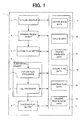
- Fig. 1 is a block diagram illustrating an example of a configuration of a vector image drawing circuit 1 according to the exemplary embodiment of the present invention.
- the vector image drawing circuit 1 includes an image data memory 2, an outline creator 3, a drawing region divider 4, an outline flag setter 5, a subdivisional drawer 6, and a continue flag setter 9.
- the subdivisional drawer 6 includes an outline flag processor 7 and a fill processor 8.
- the image data memory 2 stores vector image data 21, outline data 22, drawing subregion data 23, outline flag data 24, continue flag data 25, and drawing region image data 26.
- the vector image data 21 includes data of one or more figures configured by vector data. Figures included in the vector image data 21 are configured by one or more vector data.
- the vector data may include straight lines, Bezier curves, arcs, etc.
- Fig. 3 is an example of the vector image data 21 and illustrates one figure configured by vector data.
- the "Line” listed next indicates that the vectors are line segments.
- the start point of the line is the coordinate (3, 1).
- the coordinates of the remaining control points follow, ending with the point having a coordinate of (16, 1).
- the ending point (16, 1) has a line segment to the start point (3, 1), thereby forming a closed figure.
- the outline creator 3 reads the vector image data 21 from the image data memory 2 and defines the outline data 22 corresponding to pixels forming the outline of the figure.
- the outline creator 3 defines the outline data 22 as pixels corresponding to an outline of the figure of the vector image data 21 and stores the outline data 22 in the image data memory 2.
- the outline data 22 is represented by, for example, "+1" for a start pixel, "-1" for an end pixel, and "0" for other pixels.
- Fig. 4A and Fig. 4B illustrate a processing by the outline creator 3.
- Fig. 4A illustrates an outline made from the vector image data 21 illustrated in Fig. 3 .
- Fig. 4B illustrates the outline data 22 made corresponding to the outline of Fig. 4A .
- the outline data 22 is defined for each of the pixels having a hatching in Fig. 4B .
- start pixels are pixels having a hatching that slants to the upper right
- end pixels are pixels having a hatching that slants to the lower right.
- the drawing region divider 4 divides a drawing region into a plurality of drawing subregions having a predetermined size.
- a drawing subregion size is defined as a rectangle having a predetermined number of pixels in the vertical and horizontal directions, such that the drawing region is divided into an m x n matrix of drawing subregions.
- the drawing region is defined as one drawing subregion.
- Fig. 4B illustrates an example of a drawing region divided into drawing subregions.
- Each drawing subregion has the same size and a shape that is uniform over the drawing region.
- the drawing region is divided into a 3 ⁇ 5 matrix of drawing subregions.
- Natural numbers m and n may be provided to the drawing region subdivider 4, and the drawing region may be divided into an m ⁇ n matrix of drawing subregions.
- the size of the drawing subregion need not be uniform over the entire drawing region. For example, the sizes may be varied, such as small drawing subregions in areas of dense figures and large drawing subregions in areas of sparse figures.
- the drawing region divider 4 stores data illustrating each of the drawing subregions after the division in the image data memory 2 as the drawing subregion data 23.
- the outline flag setter 5 determines, for each of the drawing subregions, whether or not a start pixel or an end pixel is present in a drawing subregion.
- the outline flag setter 5 sets an outline flag for the drawing subregion in the case where a start pixel or an end pixel is present in the drawing subregion. For example, the outline flag is "1" for a drawing subregion having a start pixel or an end pixel, and the outline flag is "0" for a drawing subregion having none thereof.
- FIG. 4B An example of outline flags set by the outline flag setter 5 is illustrated in Fig. 4B .
- a start pixel or an end pixel is present in the drawing subregions having a cross hatching; the outline flag setter 5 sets the outline flag to "1 " for the drawing subregions having the cross hatching.
- Drawing subregions having no start pixels and no end pixels are indicated by regions having no cross hatching in Fig. 4B , and the outline flag for the drawing subregion is not set (for example, the outline flag is set as "0").
- the outline flag setter 5 stores, for each of the drawing subregions, data coupled with the outline flag in the image data memory 2 as the outline flag data 24.
- the subdivisional drawer 6 performs, for each of the drawing subregions, fill processing based on the outline data 22. For example, as illustrated in Fig. 4C , the interior pixels of the profile are filled by a fill processing.
- a fill processing by the subdivisional drawer 6 is described with reference to Figs. 5A to 5C .
- Figs. 5A to 5C one drawing subregion and the pixels inside of the drawing subregion are illustrated.
- the subdivisional drawer 6 performs a filling of the pixels by scanning the outline data defined for the pixels inside the drawing subregion, thereby performing the fill processing.
- the subdivisional drawer 6 scans pixels from the left edge of a row of pixels toward the right edge, and upon scanning the right edge of the row of pixels, continues scanning once again from the left edge of the row of pixels below.
- a scanning line one row of pixels of a drawing subregion from the left edge through the right edge.
- the fill processing starts filling pixels from a start pixel indicated by "+1" in Fig. 5B . Then, pixels are filled in the scanning direction. The filling ends when an end pixel (indicated by "-1" in Fig. 5B ) is encountered during the scanning. In the case where no end pixel is encountered in the row of pixels, i.e., scanning line, of the drawing subregion being filled, the pixels of the scanning line through the pixel at the right edge are filled. In such a case, the continue flag setter 9 sets the continue flag of the scanning line to "1".
- the continue flag setter 9 sets a continue flag for each of the scanning lines and stores the resulting continue flags in the image data memory 2 as the continue flag data 25.
- the results of the fill processing based on the outline data illustrated in Fig. 5B are illustrated in Fig. 5C .
- the scanning line of the first row of pixels has no start pixel and no end pixel, and therefore no filling is performed.
- the scanning lines of the second row of pixels and the third row of pixels perform a filling from a start pixel to an end pixel.
- the scanning line of the fourth row of pixels encounters only a start pixel, and therefore performs a filling from the start pixel through the last pixel in the row of pixels and sets a continue flag.
- FIG. 6A the center drawing subregion of the three adjacent drawing subregions illustrates the case where a fill processing is omitted.
- Fig. 6B illustrates the case where the drawing processing of the center drawing subregion is not omitted.
- start pixels of the outline data are represented by hatching that slants to the upper right, and end pixels are represented by hatching that slants to the lower right.
- Fig. 6A the drawing processing for the leftmost drawing subregion results in no continue flags being set for any of the scanning lines. Therefore, a fill processing is not necessary for the center drawing subregion. In addition, no continue flags are set for the center drawing subregion. In the rightmost drawing subregion, new start pixels are encountered, and a corresponding filling is performed.
- the drawing processing of the leftmost drawing subregion results in the continue flag setter 9 setting continue flags for the scanning lines of the second through fourth rows of pixels.
- a fill processing is performed for the center drawing subregion.
- the center drawing subregion has no outline data, and namely no end pixels, and therefore the subdivisional drawer 6 fills the scanning lines from the first pixel through the last pixel for the scanning lines having a continue flag set in the leftmost drawing subregion.
- the continue flag setter 9 sets continue flags for scanning lines of the center drawing subregion for which filling was performed, to be used in the next drawing subregion.
- the outline flag processor 7 determines an outline flag for each of the drawing subregions.
- the fill processor 8 performs a fill processing for each of the drawing subregions based on the outline data and the continue flags.
- the subdivisional drawer 6 stores the image of the entire drawing region drawn for each of the drawing subregions in the image data memory 2 as the drawing region image data 26.
- Fig. 2 is a block diagram illustrating an example of a display system using the vector image drawing circuit 1.
- the display system comprises, for example, the vector image drawing circuit 1, a display processing circuit 10, and a display device 11.
- the display processing circuit 10 is connected to the vector image drawing circuit 1 and the display device 11.
- the display processing circuit 10 reads the drawing region image data 26 created by the vector image drawing circuit 1 and displays the drawing region image data 26 on the display device 11.
- a vector image is drawn by setting, for each of the drawing subregions, the outline flag data 24 and the continue flag data 25, and determining thereby the necessity of filling each of the drawing subregions; and therefore ineffective fill processing can be omitted. Furthermore, the outline data definition processing and the scanning of the outline flags and the continue flags can be performed in parallel, thereby efficiently performing the fill processing.
- the vector image drawing circuit 1 may be configured from electronic circuits including hardware for implementing circuits such as LSI (Large Scale Integration) having embedded circuits for realizing functions for drawing the vector images recited above.
- the vector image drawing circuit I may be realized as functions of software by executing a vector image drawing program for performing the functions recited above with devices such as a digital signal processor (DSP: Digital Signal Processor).
- DSP Digital Signal Processor
- the vector image drawing program stored in ROM (Read Only Memory), etc. of the DSP is executed, and the operation of each component is controlled to perform the functions recited above, thereby realizing with software the vector image drawing circuit 1.
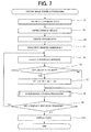
- Fig. 7 is a flowchart illustrating an example of an operation of the vector image drawing circuit 1 according to the exemplary embodiment of the present invention.
- the vector image drawing circuit 1 stores the vector image data 21 in the image data memory 2 (step S1).
- the vector image drawing circuit 1 defines a drawing region, for example, based on instructions from an operator (step S2).
- the drawing region is a predetermined region of an image to be displayed on the display device 11, including a portion or an entirety of vector image data.
- the outline creator 3 creates the outline data 22 corresponding to an outline from the vector image data 21 stored in the image data memory 2 and stores the outline data 22 in the image data memory 2 (step S3).
- the drawing region divider 4 divides the drawing region into drawing subregions by a predetermined method (step S4).
- the method for dividing may divide the drawing region into a plurality of drawing subregions of a predetermined size.
- the drawing region may be divided into an m x n matrix of drawing subregions.
- each of the drawing subregions has uniform sizes over the entire drawing region.
- the outline flag setter 5 selects one drawing subregion after the division (step S5) and discriminates whether or not the outline data 22 is present in the selected drawing subregion (step S6). In the case where a start pixel or an end pixel is present (step S6: YES), the outline flag setter 5 sets the outline flag for the drawing subregion (step S7). In the case where outline data is not present (step S6: NO), the outline flag setter 5 does not set the outline flag for the drawing subregion. Then, the subdivisional drawer 6 performs a subdivisional drawing processing (step S8).
- Fig. 8 is a flowchart illustrating an example of an operation of the subdivisional drawing processing.
- the flowchart of Fig. 8 illustrates details of the processing of step S8 illustrated in Fig. 7 .
- the subdivisional drawer 6 discriminates whether or not the outline flag is set for the selected drawing subregion (step A1). In the case where the outline flag is set (step A1: TRUE), it is discriminated whether or not the continue flag is set for the scanning line of the previously processed adjacent drawing subregion corresponding to the first scanning line (step A2).
- step A2 In the case where the continue flag is set (step A2: TRUE), a filling is started from the first pixel of the scanning line (step A3). In the case where the continue flag is not set (step A2: FALSE), it is verified whether a start pixel is present in the scanning line (step A4). In the case where a start pixel is present (step A4: YES), the filling is started from the start pixel (step A5). In the case where no start pixel is present (step A4: NO), the flow proceeds to the next scanning line (step A10).
- step A3 or step A5 it is discriminated whether or not an end pixel is present in the scanning line (step A6). In the case where an end pixel is present (step A6: YES), the filling is ended at the end pixel, i.e., without filling the end pixel (step A7). It is then determined whether any more start pixels are present (step A4). In the case where no more start pixels are present (step A4: NO), the flow proceeds with the next scanning line (step A10).
- step A6 NO
- the filling proceeds through the last pixel of the scanning line (step A8), and the continue flag setter 9 sets the continue flag for the scanning line (step A9). Then, the flow proceeds to the next scanning line (step A10).
- step A11: YES the flow returns to step A2 and once again discriminates whether or not the continue flag is set in the previously processed adjacent drawing subregion corresponding to the scanning line.
- step A11: NO the subdivisional drawing processing ends.
- step A12 it is discriminated whether or not the continue flag is set for the previously processed adjacent drawing subregion corresponding to the first scanning line (step A12).
- step A12 filling is performed from the first pixel through the last pixel of the scanning line (step A13). Then, the continue flag setter 9 sets the continue flag of the scanning line (step A14).
- step A14 In the case where the scanning line is at least partially filled (step A14), and in the case where the scanning line is not filled (step A12: FALSE), the flow proceeds to the next scanning line (step A15). In the case where an unprocessed scanning line remains in the drawing subregion undergoing the processing (step A16: YES), the flow returns to step A12, and it is once again discriminated whether or not the continue flag is set for the previously processed adjacent drawing subregion corresponding to the scanning line. In the case where no unprocessed scanning lines remain (step A16: NO), the subdivisional drawing processing ends.
- step S9 YES
- step S5 the outline flag setter 5 once again selects a drawing subregion.
- step S10 the display processing circuit 10 displays the drawing region image data 26 on the display device 11 (step S10).
- the outline flag data 24 and the continue flag data 25 are set for each of the drawing subregions; the necessity is discriminated thereby for filling the drawing subregion; and ineffective fill processing can be omitted. Furthermore, the outline data definition processing and the scanning of the outline flag and the continue flag can be performed in parallel, thereby efficiently performing the fill processing.
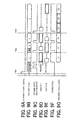
- Figs. 9A to 9G are timing chart illustrating an example of a fill processing.
- Figs. 9A to 9G illustrate the fill processing timing of the outline data example of Fig. 4B .
- a filling start signal is asserted at a timing T301, and the outline flag data and the outline data are those according to Fig. 4B .
- the subdivisional drawer 6 scans horizontally from the upper left of the drawing subregion, and therefore the outline flag data is processed in the sequence "01010 10011 10001 " as shown in Fig. 9B .
- the first digit is "0,” and therefore the scanning continues.
- the second digit is "1" and therefore an outline data read request is asserted as shown in Fig. 9C , and a reading of the outline data is started.
- Fig. 9D the outline data is written in a cache A of the second drawing subregion.
- a drawing processing (1) is started after completing the reading of the outline data as shown in Fig. 9G .
- the outline flag is "0" for the third drawing subregion, and therefore outline data is not read.
- the outline flag for the fourth drawing subregion is "1", and therefore the outline data is read and written into a cache B.
- Drawing processing is performed in parallel to the reading of the outline data and the scanning of the outline flag, and therefore the drawing processing (1) ends processing at a timing T302, at which time a reading of outline data is completed for the drawing subregion corresponding to the outline flag of the fourth drawing subregion.
- the outline flag is not continuous (the outline flag changes from "0" to "1"), and therefore it is determined whether or not a fill processing is to be continued from the continue flag of the previously processed drawing subregion.
- the continue flag is not set, and therefore a drawing processing (2) is performed regardless of the previously processed drawing subregion, thereby performing drawing processing of the fourth drawing subregion of Fig. 4B .
- the outline flag is "0" for the fifth drawing subregion, and the corresponding continue flags are not set; and therefore the drawing processing is not performed.
- the outline flag data of the sixth through the ninth drawing subregions it is determined whether or not an outline flag is present and whether or not the fill processing is to be continued.
- the outline flag is "1", and therefore the outline data is read in (cache A), and a fill processing is performed by a drawing processing (3).
- the fill processing of the sixth (leftmost of the second row) drawing subregion continues to the next drawing subregion, and therefore continue flags are set.
- the drawing subregions second and third from the left of the second row of Fig. 4B have outline flags of "0", and therefore the outline data is not read. However, the fill processing is to be continued, and therefore drawing processings are performed for each, respectively (drawing processing (4) and (5)).
- the outline data of the ninth drawing subregion i.e., the fourth from the left of the second row, has already been read in (cache B).
- continue flags are set during the previous drawing subregion, and therefore a fill processing, (drawing processing (6)), is performed until an end pixel is encountered or through the last pixel of the scanning line.
- the present invention is thus described above by illustration of a preferable exemplary embodiment, but the present invention is not limited by the exemplary embodiment recited above, and the present invention may be implemented with various modifications within the scope of the technical ideas thereof.
- this exemplary embodiment describes a case where the size of the drawing subregions is uniform over the drawing region, but the present invention may be implemented for cases where the size of the drawing subregion changes.
- the central portion of the processing of the vector image drawing circuit 1, which includes the outline creator 3, the drawing region subdivider 4, the outline flag setter 5, and the subdivisional drawer 6, may be realized by using, for example, a DSP (Digital Signal Processor).
- the vector image drawing circuit 1 for executing the processing recited above may be made by installing a program for executing the operations recited above into a memory of a DSP.
Landscapes
- Physics & Mathematics (AREA)
- General Physics & Mathematics (AREA)
- Engineering & Computer Science (AREA)
- Theoretical Computer Science (AREA)
- Image Generation (AREA)
Applications Claiming Priority (1)
| Application Number | Priority Date | Filing Date | Title |
|---|---|---|---|
| JP2007171286A JP4325812B2 (ja) | 2007-06-28 | 2007-06-28 | ベクター画像描画回路およびベクター画像描画方法 |
Publications (3)
| Publication Number | Publication Date |
|---|---|
| EP2009593A2 true EP2009593A2 (fr) | 2008-12-31 |
| EP2009593A3 EP2009593A3 (fr) | 2009-11-25 |
| EP2009593B1 EP2009593B1 (fr) | 2011-08-31 |
Family
ID=39789573
Family Applications (1)
| Application Number | Title | Priority Date | Filing Date |
|---|---|---|---|
| EP08159332A Ceased EP2009593B1 (fr) | 2007-06-28 | 2008-06-30 | Circuit de dessin d'images vectorielles et procédé pour le dessin d'images vectorielles |
Country Status (4)
| Country | Link |
|---|---|
| US (1) | US8237628B2 (fr) |
| EP (1) | EP2009593B1 (fr) |
| JP (1) | JP4325812B2 (fr) |
| CA (1) | CA2636541C (fr) |
Families Citing this family (2)
| Publication number | Priority date | Publication date | Assignee | Title |
|---|---|---|---|---|
| JP5159949B2 (ja) * | 2009-05-19 | 2013-03-13 | 三菱電機株式会社 | ベクトル図形描画装置 |
| JP2014010572A (ja) * | 2012-06-28 | 2014-01-20 | Strauss Technology Co Ltd | ベクター画像描画装置及びベクター画像描画方法 |
Citations (2)
| Publication number | Priority date | Publication date | Assignee | Title |
|---|---|---|---|---|
| JPH03168694A (ja) | 1989-11-28 | 1991-07-22 | Fujitsu Ltd | アウトラインフォント展開方式 |
| JP2007171286A (ja) | 2005-12-19 | 2007-07-05 | Tomizo Yamamoto | 線状光照射装置 |
Family Cites Families (15)
| Publication number | Priority date | Publication date | Assignee | Title |
|---|---|---|---|---|
| US5341472A (en) * | 1990-02-02 | 1994-08-23 | Apple Computer, Inc. | Efficient area description for raster displays |
| JPH03233689A (ja) | 1990-02-09 | 1991-10-17 | Fuji Xerox Co Ltd | アウトラインデータ描画装置 |
| US5553219A (en) * | 1991-05-10 | 1996-09-03 | Fuji Xerox Co., Ltd. | Font outline and bit map generator synthesizing filling data with selected outline data or duplicate outline data |
| US5355449A (en) * | 1991-09-30 | 1994-10-11 | Destiny Technology Corporation | Method and apparatus for outline font character generation in dot matrix devices |
| JPH06161420A (ja) | 1992-11-18 | 1994-06-07 | Nec Off Syst Ltd | 文字信号発生装置 |
| US5729672A (en) * | 1993-07-30 | 1998-03-17 | Videologic Limited | Ray tracing method and apparatus for projecting rays through an object represented by a set of infinite surfaces |
| US5576843A (en) * | 1993-10-29 | 1996-11-19 | Time Warner Entertainment Co., L.P. | System and method for controlling play of multiple dialog audio tracks of a software carrier |
| US5598517A (en) * | 1995-01-10 | 1997-01-28 | Evans & Sutherland Computer Corp. | Computer graphics pixel rendering system with multi-level scanning |
| US6005582A (en) * | 1995-08-04 | 1999-12-21 | Microsoft Corporation | Method and system for texture mapping images with anisotropic filtering |
| US5706479A (en) * | 1995-10-02 | 1998-01-06 | Apple Computer, Inc. | Method and apparatus for dynamically detecting overflow of a multi-layer buffer |
| US5936642A (en) * | 1996-03-29 | 1999-08-10 | Shinko Electric Industries, Co., Ltd. | Parallel graphic processing system using a network |
| DE19917092A1 (de) * | 1999-04-15 | 2000-10-26 | Sp3D Chip Design Gmbh | Verfahren zur Rasterisierung eines Graphikgrundelements |
| US20020039100A1 (en) * | 2000-06-08 | 2002-04-04 | Stephen Morphet | Memory management for systems for generating 3-dimensional computer images |
| US8933945B2 (en) * | 2002-11-27 | 2015-01-13 | Ati Technologies Ulc | Dividing work among multiple graphics pipelines using a super-tiling technique |
| US20060193527A1 (en) * | 2005-01-11 | 2006-08-31 | Florida Atlantic University | System and methods of mode determination for video compression |
-
2007
- 2007-06-28 JP JP2007171286A patent/JP4325812B2/ja not_active Expired - Fee Related
-
2008
- 2008-06-30 US US12/216,177 patent/US8237628B2/en not_active Expired - Fee Related
- 2008-06-30 CA CA2636541A patent/CA2636541C/fr not_active Expired - Fee Related
- 2008-06-30 EP EP08159332A patent/EP2009593B1/fr not_active Ceased
Patent Citations (2)
| Publication number | Priority date | Publication date | Assignee | Title |
|---|---|---|---|---|
| JPH03168694A (ja) | 1989-11-28 | 1991-07-22 | Fujitsu Ltd | アウトラインフォント展開方式 |
| JP2007171286A (ja) | 2005-12-19 | 2007-07-05 | Tomizo Yamamoto | 線状光照射装置 |
Also Published As
| Publication number | Publication date |
|---|---|
| EP2009593B1 (fr) | 2011-08-31 |
| CA2636541A1 (fr) | 2008-12-28 |
| US20090066699A1 (en) | 2009-03-12 |
| US8237628B2 (en) | 2012-08-07 |
| JP2009009428A (ja) | 2009-01-15 |
| EP2009593A3 (fr) | 2009-11-25 |
| JP4325812B2 (ja) | 2009-09-02 |
| CA2636541C (fr) | 2013-02-05 |
Similar Documents
| Publication | Publication Date | Title |
|---|---|---|
| US8237717B2 (en) | Vector image drawing device, method for vector image drawing, and computer readable recording medium | |
| US8259374B2 (en) | Image processing apparatus and image forming apparatus | |
| US9495757B2 (en) | Image processing apparatus and image processing method | |
| EP2009593B1 (fr) | Circuit de dessin d'images vectorielles et procédé pour le dessin d'images vectorielles | |
| JP5825306B2 (ja) | 画像変倍装置および画像変倍方法 | |
| US20050104893A1 (en) | Three dimensional image rendering apparatus and three dimensional image rendering method | |
| US20240428378A1 (en) | Image combining method, image combining apparatus, and recording medium recording computer-readable program | |
| US6504543B1 (en) | Polygon drawing method and polygon drawing apparatus | |
| US6529642B1 (en) | Method for enlarging/reducing digital images | |
| EP1659536A1 (fr) | Méthode et appareil pour l'échantillonage de pixels | |
| JP4858883B2 (ja) | ベクター画像描画装置、ベクター画像描画方法およびプログラム | |
| JPH10228537A (ja) | 画素面積計算装置 | |
| JP4749868B2 (ja) | 画像処理装置 | |
| JP3626709B2 (ja) | アンチエイリアス処理装置 | |
| KR100705188B1 (ko) | 문자 폰트 표시 방법 | |
| JP3493745B2 (ja) | 図形描画装置 | |
| JP5892618B2 (ja) | 描画表示装置および描画表示方法 | |
| JP6651776B2 (ja) | 画像処理装置、画像処理方法、及び、プログラム | |
| EP2988269B1 (fr) | Système et procédé de mise à l'échelle et de copier des graphiques | |
| JP2011028641A (ja) | 画像処理装置及び画像処理方法 | |
| JP4840033B2 (ja) | 画像処理プログラムおよび画像処理装置 | |
| US20220262053A1 (en) | Image processing apparatus, image processing method, and program | |
| JPH0683968A (ja) | 画像処理装置 | |
| JPH01100590A (ja) | 表示制御方式 | |
| JPH09185358A (ja) | イメージデータ出力方法および装置 |
Legal Events
| Date | Code | Title | Description |
|---|---|---|---|
| PUAI | Public reference made under article 153(3) epc to a published international application that has entered the european phase |
Free format text: ORIGINAL CODE: 0009012 |
|
| AK | Designated contracting states |
Kind code of ref document: A2 Designated state(s): AT BE BG CH CY CZ DE DK EE ES FI FR GB GR HR HU IE IS IT LI LT LU LV MC MT NL NO PL PT RO SE SI SK TR |
|
| AX | Request for extension of the european patent |
Extension state: AL BA MK RS |
|
| PUAL | Search report despatched |
Free format text: ORIGINAL CODE: 0009013 |
|
| AK | Designated contracting states |
Kind code of ref document: A3 Designated state(s): AT BE BG CH CY CZ DE DK EE ES FI FR GB GR HR HU IE IS IT LI LT LU LV MC MT NL NO PL PT RO SE SI SK TR |
|
| AX | Request for extension of the european patent |
Extension state: AL BA MK RS |
|
| RIC1 | Information provided on ipc code assigned before grant |
Ipc: G06T 11/40 20060101ALI20091020BHEP Ipc: G06T 11/20 20060101AFI20081007BHEP |
|
| 17P | Request for examination filed |
Effective date: 20100521 |
|
| AKX | Designation fees paid |
Designated state(s): DE FI GB |
|
| GRAP | Despatch of communication of intention to grant a patent |
Free format text: ORIGINAL CODE: EPIDOSNIGR1 |
|
| RIC1 | Information provided on ipc code assigned before grant |
Ipc: G06T 11/20 20060101AFI20110202BHEP Ipc: G06T 11/40 20060101ALI20110202BHEP |
|
| GRAS | Grant fee paid |
Free format text: ORIGINAL CODE: EPIDOSNIGR3 |
|
| GRAA | (expected) grant |
Free format text: ORIGINAL CODE: 0009210 |
|
| AK | Designated contracting states |
Kind code of ref document: B1 Designated state(s): DE FI GB |
|
| REG | Reference to a national code |
Ref country code: GB Ref legal event code: FG4D |
|
| REG | Reference to a national code |
Ref country code: DE Ref legal event code: R096 Ref document number: 602008009246 Country of ref document: DE Effective date: 20111110 |
|
| PLBE | No opposition filed within time limit |
Free format text: ORIGINAL CODE: 0009261 |
|
| STAA | Information on the status of an ep patent application or granted ep patent |
Free format text: STATUS: NO OPPOSITION FILED WITHIN TIME LIMIT |
|
| 26N | No opposition filed |
Effective date: 20120601 |
|
| REG | Reference to a national code |
Ref country code: DE Ref legal event code: R097 Ref document number: 602008009246 Country of ref document: DE Effective date: 20120601 |
|
| REG | Reference to a national code |
Ref country code: DE Ref legal event code: R082 Ref document number: 602008009246 Country of ref document: DE Representative=s name: VOSSIUS & PARTNER PATENTANWAELTE RECHTSANWAELT, DE |
|
| REG | Reference to a national code |
Ref country code: DE Ref legal event code: R081 Ref document number: 602008009246 Country of ref document: DE Owner name: NEC SOLUTION INNOVATORS, LTD., TOKYO, JP Free format text: FORMER OWNER: NEC SYSTEM TECHNOLOGIES, LTD., OSAKA, CHUO-KU, JP Effective date: 20140728 Ref country code: DE Ref legal event code: R082 Ref document number: 602008009246 Country of ref document: DE Representative=s name: VOSSIUS & PARTNER PATENTANWAELTE RECHTSANWAELT, DE Effective date: 20140728 |
|
| REG | Reference to a national code |
Ref country code: GB Ref legal event code: 732E Free format text: REGISTERED BETWEEN 20150305 AND 20150311 |
|
| PGFP | Annual fee paid to national office [announced via postgrant information from national office to epo] |
Ref country code: DE Payment date: 20180619 Year of fee payment: 11 Ref country code: FI Payment date: 20180612 Year of fee payment: 11 |
|
| PGFP | Annual fee paid to national office [announced via postgrant information from national office to epo] |
Ref country code: GB Payment date: 20180627 Year of fee payment: 11 |
|
| REG | Reference to a national code |
Ref country code: DE Ref legal event code: R119 Ref document number: 602008009246 Country of ref document: DE |
|
| REG | Reference to a national code |
Ref country code: FI Ref legal event code: MAE |
|
| PG25 | Lapsed in a contracting state [announced via postgrant information from national office to epo] |
Ref country code: FI Free format text: LAPSE BECAUSE OF NON-PAYMENT OF DUE FEES Effective date: 20190630 |
|
| GBPC | Gb: european patent ceased through non-payment of renewal fee |
Effective date: 20190630 |
|
| PG25 | Lapsed in a contracting state [announced via postgrant information from national office to epo] |
Ref country code: DE Free format text: LAPSE BECAUSE OF NON-PAYMENT OF DUE FEES Effective date: 20200101 Ref country code: GB Free format text: LAPSE BECAUSE OF NON-PAYMENT OF DUE FEES Effective date: 20190630 |