EP2009756B1 - Socle d'un appareil d'installation destiné à la réception d'éléments de contact électriques - Google Patents
Socle d'un appareil d'installation destiné à la réception d'éléments de contact électriques Download PDFInfo
- Publication number
- EP2009756B1 EP2009756B1 EP08009435.2A EP08009435A EP2009756B1 EP 2009756 B1 EP2009756 B1 EP 2009756B1 EP 08009435 A EP08009435 A EP 08009435A EP 2009756 B1 EP2009756 B1 EP 2009756B1
- Authority
- EP
- European Patent Office
- Prior art keywords
- latching
- device base
- device socket
- main section
- mounting plate
- Prior art date
- Legal status (The legal status is an assumption and is not a legal conclusion. Google has not performed a legal analysis and makes no representation as to the accuracy of the status listed.)
- Active
Links
Images

Classifications
-
- H—ELECTRICITY
- H02—GENERATION; CONVERSION OR DISTRIBUTION OF ELECTRIC POWER
- H02G—INSTALLATION OF ELECTRIC CABLES OR LINES, OR OF COMBINED OPTICAL AND ELECTRIC CABLES OR LINES
- H02G3/00—Installations of electric cables or lines or protective tubing therefor in or on buildings, equivalent structures or vehicles
- H02G3/02—Details
- H02G3/08—Distribution boxes; Connection or junction boxes
- H02G3/10—Distribution boxes; Connection or junction boxes for surface mounting on a wall
Definitions
- the invention relates to a device base of an installation device for receiving electrical contact parts according to the preamble of claim 1. It is for example a socket device base or switch device base or button device base or accessory device base.
- the invention can be used in installation devices for surface mounting.
- a device carrier for fastening an electrical installation device which has radially protruding retaining tabs on the bottom.
- the equipment rack has a base plate with openings for attaching the equipment rack to a wall.
- Two locking hooks are arranged radially opposite one another on the base plate and have an insertion bevel on their upper side.
- the locking hooks are additionally stiffened with the help of ribs 16 on the rear.
- the invention is based on the object of specifying a device base of an installation device for receiving electrical contact parts, which allows tolerance compensation.
- the elastically behaving latching element not only enables tolerance compensation but also excessive bending of the base of the device - e.g. B. when tightening a central nut to secure a covering cap (for example, cap with socket pot) - is counteracted.
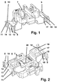
- FIG. 2 is a perspective view of the underside of a device base shown. This view shows in particular the resilient interaction between a latching element 8 or 9 with the ribs 15, 16 and the stop surface 17 of the main section 7 of the device base 6 directly opposite these ribs 15, 16.
- the formation of a gap 18 between each stop surface 17 is important and a rib 15, 16.
- the width of the gap 18 determines the possibility of lateral bending of a latching element 8, 9 towards the main section 7 of the device base 6.
- the Figures 1 and 2 also show the exact design of the guide surface 13.
- the edge guide webs 11, 12 are V-shaped to each other, so that the guide surface 13 is wider on the underside than on the top (near the locking edge 14) and thus trapezoidal.
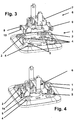
- FIG. 3 shows a perspective view of the mounting plate / device base configuration prior to assembly.
- the mounting plate 1 can be mounted on a wall via several mounting holes 4.
- the mounting plate 1 has two locking hooks 2, 3 lying opposite one another.
- the locking hooks 2, 3 are on the guide surfaces 13 of the two locking elements 8, 9 put on.
- the width of the guide surfaces 13 on their underside is greater than the width of the latching hooks 2, 3, so that a precise (centered) placement of the device base 6 on the mounting plate 1 is not required and placement is made easier.
- a second step the device base 6 is pressed against the mounting plate 1.
- the latching hooks 2, 3 slide along the guide surfaces 13. Due to the upwardly tapering shape of the guide surfaces 13, a possible lateral offset between the device base 6 and the mounting plate 1 is automatically corrected during insertion, ie. H. the arrangement of the device base 6 is automatically centered on the mounting plate 1.
- the latching elements 8, 9 bend resiliently around the flexible webs acting as the "axis of rotation" in the direction of the main section 7 until the ribs 15, 16 press against the stop surface 17.
- Several ribs 5 of the mounting plate 1 serve as a lateral stop for the latched device base 6.
- FIG. 4 a perspective view of the configuration of the mounting plate / device base after assembly is shown, ie the locking between device base 6 and mounting plate 1 with the locking hooks 2, 3 reaching over the locking edges 14 is shown.
- Figure 3 shows a perspective view of the mounting plate / device base / cap configuration prior to assembly.
- the configuration shown is the cap 21 with the socket pot, which is connected to the device base 6 by means of a central screw 22 - see the central nut 20 there.
Landscapes
- Engineering & Computer Science (AREA)
- Architecture (AREA)
- Civil Engineering (AREA)
- Structural Engineering (AREA)
- Casings For Electric Apparatus (AREA)
- Connecting Device With Holders (AREA)
- Connection Of Plates (AREA)
Claims (3)
- Socle d'appareil (6) d'un appareil d'installation pour recevoir des pièces de contact électriques, lequel peut être fixé par le biais d'au moins un élément d'encliquetage (8, 9) sur une plaque de montage (1), caractérisé en ce que l'au moins un élément d'encliquetage (8, 9) est connecté à la portion principale (7) du socle d'appareil (6) par le biais d'une nervure flexible (10) et en ce qu'entre l'élément d'encliquetage (8, 9) et la portion principale (7) du socle d'appareil (6) est réalisée une fente (18) de largeur prédéfinie, qui permet un fléchissement latéral de l'élément d'encliquetage (8, 9) par rapport à la portion principale du socle d'appareil (6) et l'élément d'encliquetage (8, 9) présente deux nervures de guidage (11, 12) du côté des bords, qui limitent des deux côtés une surface de guidage (13) pour le guidage d'un crochet d'encliquetage (2, 3) connecté à la plaque de montage (1), la surface de guidage (13) se terminant au niveau de son côté supérieur avec une arête d'encliquetage (14) pour le crochet d'encliquetage (2, 3).
- Socle d'appareil selon la revendication 1, caractérisé en ce que la surface de guidage (13) est réalisée en forme de trapèze de telle sorte que le côté inférieur de la surface de guidage (13) prévu pour l'introduction du crochet d'encliquetage (2, 3) soit plus large que son côté supérieur à proximité de l'arête d'encliquetage (14).
- Socle d'appareil selon la revendication 2, caractérisé en ce que l'élément d'encliquetage (8, 9) présente au niveau du côté arrière de la surface de guidage (13) au moins une ailette (15, 16) qui est orientée vers une surface de butée opposée (17) de la portion principale (7) du socle d'appareil (6), la fente (18) étant réalisée entre l'ailette (15, 16) et la surface de butée (17).
Applications Claiming Priority (1)
| Application Number | Priority Date | Filing Date | Title |
|---|---|---|---|
| DE102007029247A DE102007029247B3 (de) | 2007-06-25 | 2007-06-25 | Gerätesockel eines Installationsgerätes zur Aufnahme von elektrischen Kontaktteilen |
Publications (3)
| Publication Number | Publication Date |
|---|---|
| EP2009756A2 EP2009756A2 (fr) | 2008-12-31 |
| EP2009756A3 EP2009756A3 (fr) | 2016-10-19 |
| EP2009756B1 true EP2009756B1 (fr) | 2020-11-18 |
Family
ID=39500015
Family Applications (1)
| Application Number | Title | Priority Date | Filing Date |
|---|---|---|---|
| EP08009435.2A Active EP2009756B1 (fr) | 2007-06-25 | 2008-05-23 | Socle d'un appareil d'installation destiné à la réception d'éléments de contact électriques |
Country Status (2)
| Country | Link |
|---|---|
| EP (1) | EP2009756B1 (fr) |
| DE (1) | DE102007029247B3 (fr) |
Families Citing this family (1)
| Publication number | Priority date | Publication date | Assignee | Title |
|---|---|---|---|---|
| DE202017107144U1 (de) * | 2017-11-24 | 2019-02-27 | Wago Verwaltungsgesellschaft Mbh | Set aus Steckverbinder und Halteelement sowie Steckverbinder und Halteelement hierzu |
Family Cites Families (8)
| Publication number | Priority date | Publication date | Assignee | Title |
|---|---|---|---|---|
| BE637467A (fr) * | 1962-09-18 | |||
| DE7608855U1 (de) * | 1976-03-23 | 1976-07-15 | Brown, Boveri & Cie Ag, 6800 Mannheim | Elektrischer Installationsschalter oder -Taster |
| US5223673A (en) * | 1990-12-10 | 1993-06-29 | Mason Gay L | Modular electrical outlet assembly |
| DE29610554U1 (de) * | 1996-04-24 | 1997-09-18 | Gira Giersiepen Gmbh & Co Kg, 42477 Radevormwald | Elektrisches Installationsgerät insbesondere zur Aufputz-Montage |
| DE19716906A1 (de) * | 1996-04-24 | 1997-12-11 | Giersiepen Gira Gmbh | Elektrisches Installationsgerät insbesondere zur Aufputz-Montage |
| DE29703727U1 (de) * | 1997-03-01 | 1997-04-30 | Gira Giersiepen Gmbh & Co Kg, 42477 Radevormwald | Elektrisches Installationsgerät zur Aufputz-Montage |
| EP1322012B1 (fr) * | 2001-12-18 | 2009-08-19 | Feller AG | Dispositif de fixation en surface d'un interface d'installation domestique |
| DE20213032U1 (de) * | 2002-08-24 | 2004-01-08 | Tehalit Gmbh & Co. Kg | Geräteträger für Sockelleisten-Kanäle |
-
2007
- 2007-06-25 DE DE102007029247A patent/DE102007029247B3/de active Active
-
2008
- 2008-05-23 EP EP08009435.2A patent/EP2009756B1/fr active Active
Non-Patent Citations (1)
| Title |
|---|
| None * |
Also Published As
| Publication number | Publication date |
|---|---|
| EP2009756A3 (fr) | 2016-10-19 |
| DE102007029247B3 (de) | 2009-01-08 |
| EP2009756A2 (fr) | 2008-12-31 |
Similar Documents
| Publication | Publication Date | Title |
|---|---|---|
| DE69607325T2 (de) | Schnappbefestigung für sonnenblende und elektrische verbinder für sonnenblendbefestigungen | |
| EP3117112B1 (fr) | Système de fixation servant à monter des appareils, en particulier des appareils électriques | |
| EP2883284B1 (fr) | Module de connexion | |
| EP3084891B1 (fr) | Élément métallique de connexion de conducteur de terre et bloc de jonction électrique | |
| EP2491619A1 (fr) | Borne de raccordement à ressort de connexion doté de branches | |
| EP2738884B1 (fr) | Montage d'un dispositif de raccordement | |
| WO2012025181A2 (fr) | Dispositif de connexion et moteur électrique pourvu d'un tel dispositif de connexion | |
| EP3843221A1 (fr) | Cadre de support pour un connecteur | |
| DE4036249A1 (de) | Aus einem metallischen werkstoff, wie stahlblech, bestehender kanal zur unterbringung von elektrischen installationseinrichtungen | |
| EP2012390B1 (fr) | Pince de mise à la terre destinée à l'équilibrage du potentiel de canaux de câblage | |
| EP2009756B1 (fr) | Socle d'un appareil d'installation destiné à la réception d'éléments de contact électriques | |
| EP0248160A2 (fr) | Support pour barres omnibus | |
| DE10035795B4 (de) | Klemmschuhanordnung | |
| DE102014219996B3 (de) | Blitzschutz-Klemmenanordnung | |
| EP3369607B1 (fr) | Système de rail conducteur | |
| DE102011120247B4 (de) | Batterie und Fahrzeug mit einer Batterie | |
| EP1489712B1 (fr) | Soulagement de contrainte pour câble électrique | |
| EP2009757B1 (fr) | Appareil d'installation doté d'un socle d'appareil fixé sur une plaque de montage | |
| EP3763559B1 (fr) | Système de rail conducteur | |
| EP1701422B1 (fr) | Boitier d'appareil pour dispositif d'installation électrique | |
| DE102008019763A1 (de) | Befestigungsvorrichtung zur lösbaren rastenden Halterung eines elektrischen Verteilers | |
| EP3758151B1 (fr) | Agencement de borne de raccordement permettant de raccorder au moins un conducteur électrique | |
| DE102004059815B4 (de) | Montageträger für Unterflurdose | |
| DE2604764B2 (de) | Elektrische anschlussvorrichtung fuer eine gekapselte kaeltemaschine | |
| DE102014014753A1 (de) | Halteeinrichtung für einen Querträger in einem elektrischen Schaltschrank und Schaltschrank |
Legal Events
| Date | Code | Title | Description |
|---|---|---|---|
| PUAI | Public reference made under article 153(3) epc to a published international application that has entered the european phase |
Free format text: ORIGINAL CODE: 0009012 |
|
| AK | Designated contracting states |
Kind code of ref document: A2 Designated state(s): AT BE BG CH CY CZ DE DK EE ES FI FR GB GR HR HU IE IS IT LI LT LU LV MC MT NL NO PL PT RO SE SI SK TR |
|
| AX | Request for extension of the european patent |
Extension state: AL BA MK RS |
|
| PUAL | Search report despatched |
Free format text: ORIGINAL CODE: 0009013 |
|
| AK | Designated contracting states |
Kind code of ref document: A3 Designated state(s): AT BE BG CH CY CZ DE DK EE ES FI FR GB GR HR HU IE IS IT LI LT LU LV MC MT NL NO PL PT RO SE SI SK TR |
|
| AX | Request for extension of the european patent |
Extension state: AL BA MK RS |
|
| RIC1 | Information provided on ipc code assigned before grant |
Ipc: H02G 3/10 20060101AFI20160915BHEP |
|
| STAA | Information on the status of an ep patent application or granted ep patent |
Free format text: STATUS: REQUEST FOR EXAMINATION WAS MADE |
|
| 17P | Request for examination filed |
Effective date: 20170328 |
|
| AKX | Designation fees paid |
Designated state(s): DE NL |
|
| AXX | Extension fees paid |
Extension state: BA Extension state: AL Extension state: RS Extension state: MK |
|
| RAP1 | Party data changed (applicant data changed or rights of an application transferred) |
Owner name: ABB SCHWEIZ AG |
|
| GRAP | Despatch of communication of intention to grant a patent |
Free format text: ORIGINAL CODE: EPIDOSNIGR1 |
|
| STAA | Information on the status of an ep patent application or granted ep patent |
Free format text: STATUS: GRANT OF PATENT IS INTENDED |
|
| INTG | Intention to grant announced |
Effective date: 20200730 |
|
| GRAS | Grant fee paid |
Free format text: ORIGINAL CODE: EPIDOSNIGR3 |
|
| GRAA | (expected) grant |
Free format text: ORIGINAL CODE: 0009210 |
|
| STAA | Information on the status of an ep patent application or granted ep patent |
Free format text: STATUS: THE PATENT HAS BEEN GRANTED |
|
| AK | Designated contracting states |
Kind code of ref document: B1 Designated state(s): DE NL |
|
| REG | Reference to a national code |
Ref country code: DE Ref legal event code: R096 Ref document number: 502008017164 Country of ref document: DE |
|
| REG | Reference to a national code |
Ref country code: NL Ref legal event code: FP |
|
| REG | Reference to a national code |
Ref country code: DE Ref legal event code: R097 Ref document number: 502008017164 Country of ref document: DE |
|
| PLBE | No opposition filed within time limit |
Free format text: ORIGINAL CODE: 0009261 |
|
| STAA | Information on the status of an ep patent application or granted ep patent |
Free format text: STATUS: NO OPPOSITION FILED WITHIN TIME LIMIT |
|
| 26N | No opposition filed |
Effective date: 20210819 |
|
| REG | Reference to a national code |
Ref country code: DE Ref legal event code: R119 Ref document number: 502008017164 Country of ref document: DE |
|
| PG25 | Lapsed in a contracting state [announced via postgrant information from national office to epo] |
Ref country code: DE Free format text: LAPSE BECAUSE OF NON-PAYMENT OF DUE FEES Effective date: 20211201 |
|
| PGFP | Annual fee paid to national office [announced via postgrant information from national office to epo] |
Ref country code: NL Payment date: 20250521 Year of fee payment: 18 |