EP2009757B1 - Appareil d'installation doté d'un socle d'appareil fixé sur une plaque de montage - Google Patents
Appareil d'installation doté d'un socle d'appareil fixé sur une plaque de montage Download PDFInfo
- Publication number
- EP2009757B1 EP2009757B1 EP08009879.1A EP08009879A EP2009757B1 EP 2009757 B1 EP2009757 B1 EP 2009757B1 EP 08009879 A EP08009879 A EP 08009879A EP 2009757 B1 EP2009757 B1 EP 2009757B1
- Authority
- EP
- European Patent Office
- Prior art keywords
- adapter
- device base
- socket
- latching
- mounting plate
- Prior art date
- Legal status (The legal status is an assumption and is not a legal conclusion. Google has not performed a legal analysis and makes no representation as to the accuracy of the status listed.)
- Active
Links
Images


Classifications
-
- H—ELECTRICITY
- H02—GENERATION; CONVERSION OR DISTRIBUTION OF ELECTRIC POWER
- H02G—INSTALLATION OF ELECTRIC CABLES OR LINES, OR OF COMBINED OPTICAL AND ELECTRIC CABLES OR LINES
- H02G3/00—Installations of electric cables or lines or protective tubing therefor in or on buildings, equivalent structures or vehicles
- H02G3/02—Details
- H02G3/08—Distribution boxes; Connection or junction boxes
- H02G3/10—Distribution boxes; Connection or junction boxes for surface mounting on a wall
-
- H—ELECTRICITY
- H02—GENERATION; CONVERSION OR DISTRIBUTION OF ELECTRIC POWER
- H02G—INSTALLATION OF ELECTRIC CABLES OR LINES, OR OF COMBINED OPTICAL AND ELECTRIC CABLES OR LINES
- H02G3/00—Installations of electric cables or lines or protective tubing therefor in or on buildings, equivalent structures or vehicles
- H02G3/02—Details
- H02G3/08—Distribution boxes; Connection or junction boxes
- H02G3/14—Fastening of cover or lid to box
Definitions
- the invention relates to an installation device with a mounted on a mounting plate device base according to the preamble of claim 1. It is, for example, a socket-device base or switch-device base or button-device base or accessory device base.
- the invention can be used in installation devices for surface mounting.
- the invention has for its object to provide an installation device with a mounted on a mounting plate device base, in which different device base, such as socket-device base or switch device base, can be mounted on one and the same mounting plate.
- the achievable with the present invention consist in particular that using one and the same mounting plate and different device socket concerning sockets, switches, buttons, accessories and differentiated adapter for this device base different installation devices, d.
- H. Surface-mounted sockets, surface-mounted switches, surface-mounted push-buttons, surface-mounted accessories can be produced inexpensively.
- the adapter in addition to the generation of a uniform locking geometry and a tolerance compensation is achieved and it is an excessive stress (bending stress) of the device base prevented, z.
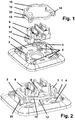
- FIG. 2 is a perspective view of the configuration mounting plate / socket device socket / socket adapter shown after installation.
- the locking hooks 2, 3 of the mounting plate 1 engage over the locking edges 20 of the socket adapter 12.
- the bracket 15 of the socket adapter 12 engages over the (in Fig. 2 hidden) stop surfaces 9, 10 of the socket-device base. 6
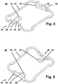
- edge-side guide webs 17, 18 are V-shaped to each other, so that the guide surface 19 is wider at the bottom than at the top (near the locking edge 20) and thus formed trapezoidal.
- bracket 15 On bracket 15 are two mutually opposite elastic compensation elements 23 (resilient adapter surfaces) arranged, which in the assembled state - see Fig. 2 - Press resiliently against the stop surfaces 9 of the socket-device base 6.
- edge-side guide webs 29, 30 are V-shaped to each other, so that the guide surface 31 is wider at the bottom than at the top (near the locking edge 32) and thus formed trapezoidal.
- bracket 27 two opposing elastic compensation elements 33 (resilient adapter surfaces) are arranged, which in the assembled state resiliently against corresponding abutment surfaces of the switch device base (see also the switch device base 37 in Fig. 8 ) to press.
- the adapters are of course mainly intended to produce a uniform snap-in geometry, ie. H. the different device / component geometries of different device sockets (socket device base or switch device base and other device base) on a uniform catch, the mounting plate to attach.
- the adapter eg socket adapter 12 or switch adapter 24
- the device base eg socket device base 6 or switch device base 37.
- the unit device base + adapter is placed on the mounting plate 1, so that the latching hooks 2, 3 on the guide surfaces 19 or 31 of the two Verrastungs institute 13, 14 or 25, 26 sit.
- the width of the guide surfaces 19, 31 on its underside is greater than the width of the latching hooks 2, 3, whereby a precise (centered) placing the unit unit base + adapter on the mounting plate 1 is not required and the placement is facilitated.
- the adapter (socket adapter 12 or switch adapter 24) is pressed against the mounting plate 1.
- the latching hooks 2, 3 slide along the guide surfaces 19 or 31.
- 31 is a possible lateral offset between the device base and Automatically corrects mounting plate during insertion, ie there is an automatic centering of the arrangement of the device base (socket-device base 6 or switch device base 37) on the mounting plate.
- a fourth step there is a locking between the device base and mounting plate 1 by the latching hooks 2, 3 engage over the locking edges 20 or 32.
- FIG. 7 is a perspective view of the configuration mounting plate / socket device socket / socket adapter / cap shown before mounting. After the locking of the socket-device base 6 is done on the mounting plate 1 by means of the socket adapter 12, the cap 35 is placed and fixed by means of central screw 36 to the socket-device base 6.
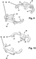
- FIG. 8 is a perspective view of the configuration mounting plate / switch device base / switch adapter shown after installation. It can be seen that the mounting plate 1 via its two latching hooks 2, 3 with an alternative switch adapter 38 - consisting of two separate and similarly formed brackets 39, 40 - is locked, each with a Verrastungselement 25, 26 and an elastic Compensation element 33 are provided and via the elastic compensating elements 33 (resilient adapter surfaces) cause attachment of the switch device base 37.
- the brackets 39, 40 each have guide lugs 41, which engage in guide grooves 42 of the switch device base 37.
- the guide lugs 41 facilitate the correct (twist-free) placement of the adapter on the device base and ensure a "temporary" fixation of the units unit base + adapter safely.
- the other explanations above are also valid for the alternative switch adapter 38.
Landscapes
- Engineering & Computer Science (AREA)
- Architecture (AREA)
- Civil Engineering (AREA)
- Structural Engineering (AREA)
- Details Of Connecting Devices For Male And Female Coupling (AREA)
- Connector Housings Or Holding Contact Members (AREA)
- Switch Cases, Indication, And Locking (AREA)
Claims (6)
- Appareil d'installation comportant un socle d'appareil (6, 37) fixé à une plaque de montage (1), pour recevoir des pièces de contact électriques, caractérisé en ce qu'au moins un adaptateur (12, 24, 38) est d'une part relié de manière amovible par l'intermédiaire d'au moins un élément d'encliquetage (13, 14, 25, 26) à la plaque de montage (1) et est d'autre part comprimé, par l'intermédiaire d'au moins un élément de compensation élastique (23, 33), contre une surface de butée (9) du socle d'appareil (6, 37), et en ce qu'il est enfin ainsi fixé à la plaque de montage (1).
- Appareil d'installation selon la revendication 1, caractérisé par au moins une surface d'adaptation non flexible (22, 23) qui est comprimée contre une surface de butée (10) du socle d'appareil (6, 37).
- Appareil d'installation selon la revendication 1 ou 2, caractérisé en ce que l'élément d'encliquetage (13, 14, 25, 26) comporte deux barrettes de guidage de bordure (17, 18, 29, 30), qui délimitent des deux côtés une surface de guidage (19, 31) destinée au guidage d'un crochet d'encliquetage (2, 3) relié à la plaque de montage (1), dans lequel la surface de guidage (19, 31) se termine, au niveau de sa face supérieure, par une arête d'encliquetage (20, 32) destinée aux crochets d'encliquetage (2, 3).
- Appareil d'installation selon la revendication 3, caractérisé en ce que la surface de guidage (19, 31) est réalisée de manière à présenter une forme trapézoïdale afin que la face inférieure de la surface de guidage (19, 31) servant au guidage du crochet d'encliquetage (2, 3) soit plus large que sa face supérieure à proximité de l'arête d'encliquetage (20, 32).
- Appareil d'installation selon l'une quelconque des revendications précédentes, caractérisé en ce que l'adaptateur (12, 24) comporte un étrier (15, 27) circonférentiel qui est pourvu de deux éléments d'encliquetage (13, 14, 25, 26) mutuellement opposés et de deux éléments de compensation élastiques (23, 33) mutuellement opposés.
- Appareil d'installation selon les revendications 1 à 4, caractérisé en ce que l'adaptateur (38) est constitué de deux étriers (39, 40) séparés qui sont pourvus d'un élément d'encliquetage (25, 26) et d'un élément de compensation élastique (33).
Applications Claiming Priority (1)
| Application Number | Priority Date | Filing Date | Title |
|---|---|---|---|
| DE102007029246.7A DE102007029246B4 (de) | 2007-06-25 | 2007-06-25 | Installationsgerät mit einem auf einer Montageplatte befestigten Gerätesockel |
Publications (3)
| Publication Number | Publication Date |
|---|---|
| EP2009757A2 EP2009757A2 (fr) | 2008-12-31 |
| EP2009757A3 EP2009757A3 (fr) | 2016-10-05 |
| EP2009757B1 true EP2009757B1 (fr) | 2017-09-27 |
Family
ID=39791578
Family Applications (1)
| Application Number | Title | Priority Date | Filing Date |
|---|---|---|---|
| EP08009879.1A Active EP2009757B1 (fr) | 2007-06-25 | 2008-05-30 | Appareil d'installation doté d'un socle d'appareil fixé sur une plaque de montage |
Country Status (2)
| Country | Link |
|---|---|
| EP (1) | EP2009757B1 (fr) |
| DE (1) | DE102007029246B4 (fr) |
Families Citing this family (1)
| Publication number | Priority date | Publication date | Assignee | Title |
|---|---|---|---|---|
| FR2986669B1 (fr) * | 2012-02-03 | 2014-10-31 | Legrand France | Support multi-appareillages de boitier electrique multipostes |
Family Cites Families (6)
| Publication number | Priority date | Publication date | Assignee | Title |
|---|---|---|---|---|
| US5594208A (en) * | 1995-02-02 | 1997-01-14 | The Wiremold Company | Molded plastic electric outlet box with snap-on base and snap-on face plate |
| DE29610554U1 (de) | 1996-04-24 | 1997-09-18 | Gira Giersiepen Gmbh & Co Kg, 42477 Radevormwald | Elektrisches Installationsgerät insbesondere zur Aufputz-Montage |
| DE19704022C2 (de) * | 1997-02-04 | 1999-06-02 | Giersiepen Gira Gmbh | Elektrisches Aufputzinstallationsgehäuse |
| DE10227399B4 (de) * | 2002-06-20 | 2004-10-28 | Abb Patent Gmbh | Elektrisches Installationsgerät mit Tragrahmen und mindestens einem an diesem befestigten Einsatz |
| DE202004005837U1 (de) * | 2004-04-14 | 2004-07-08 | Enocean Gmbh | Schaltergehäuse zur Aufputzmontage und zur Aufnahme eines elektronischen Moduls |
| DE102005052794B4 (de) * | 2005-11-05 | 2007-12-13 | Abb Patent Gmbh | Halteelement zur Befestigung eines Abdeckrahmens eines Installationsgerätes |
-
2007
- 2007-06-25 DE DE102007029246.7A patent/DE102007029246B4/de not_active Expired - Fee Related
-
2008
- 2008-05-30 EP EP08009879.1A patent/EP2009757B1/fr active Active
Non-Patent Citations (1)
| Title |
|---|
| None * |
Also Published As
| Publication number | Publication date |
|---|---|
| EP2009757A2 (fr) | 2008-12-31 |
| DE102007029246A1 (de) | 2009-01-02 |
| DE102007029246B4 (de) | 2016-02-04 |
| EP2009757A3 (fr) | 2016-10-05 |
Similar Documents
| Publication | Publication Date | Title |
|---|---|---|
| DE10304278B4 (de) | Struktur zur Befestigung einer Anzeigeeinheit an einer Instrumentenkonsole eines Automobils | |
| EP0159554B1 (fr) | Unité de montage d'appareil pour plinthes formant des canalisations d'installation | |
| DE3882421T2 (de) | Elektrischer Gerätesockel zum Aufstellen in einem Leitungsführungskanal. | |
| EP2738884A1 (fr) | Montage d'un dispositif de raccordement | |
| DE4432509A1 (de) | Elektro-Installationsgerät, insbesondere für Kabelkanäle | |
| DE10300723A1 (de) | Sammelschienensystem und Anschluss- oder Geräte-Adapter | |
| EP2009757B1 (fr) | Appareil d'installation doté d'un socle d'appareil fixé sur une plaque de montage | |
| DE10037089C2 (de) | Befestigungsanordnung für eine flache Schaltanordnung | |
| EP3309904B1 (fr) | Logement de raccordement d'au moins un toron de câbles d'un câble | |
| EP0685906A1 (fr) | Procédé pour la fabrication d'un appareil électrique et appareil électrique réalisé d'aprés ce procédé | |
| DE102017006870A1 (de) | Elektrisches Installationsgerät | |
| DE102004024093B4 (de) | Abdeckung | |
| EP0887901A2 (fr) | Dispositif de compensation des différences de potentiel | |
| DE102019121165A1 (de) | System zur Realisierung einer Leuchte mit elektrischem Abgriff mit Leiterhalter | |
| EP3885648B1 (fr) | Système de fourniture d'un luminaire pourvu de branchement électrique comprenant un dispositif contact traversant | |
| DE19610037C2 (de) | Baugruppenträger | |
| DE102007029247B3 (de) | Gerätesockel eines Installationsgerätes zur Aufnahme von elektrischen Kontaktteilen | |
| DE102019123764B4 (de) | Elektrisches Installationsgerät | |
| DE102006018800B3 (de) | Halteelement zur Befestigung eines Abdeckrahmens eines Installationsgerätes | |
| DE10345423A1 (de) | Halterung | |
| EP4135139B1 (fr) | Porte-composant pour composants électromécaniques | |
| EP0355524A2 (fr) | Canalisation pour câble | |
| EP3996221B1 (fr) | Dispositif de fixation de rail porteur, agencement et armoire de commande | |
| DE102006060231B4 (de) | Elektrisches/elektronisches Installationsgerät | |
| DE102024115467B4 (de) | Leiterseilklemme und Potentialausgleichsanordnung mit Leiterseilklemme |
Legal Events
| Date | Code | Title | Description |
|---|---|---|---|
| PUAI | Public reference made under article 153(3) epc to a published international application that has entered the european phase |
Free format text: ORIGINAL CODE: 0009012 |
|
| AK | Designated contracting states |
Kind code of ref document: A2 Designated state(s): AT BE BG CH CY CZ DE DK EE ES FI FR GB GR HR HU IE IS IT LI LT LU LV MC MT NL NO PL PT RO SE SI SK TR |
|
| AX | Request for extension of the european patent |
Extension state: AL BA MK RS |
|
| PUAL | Search report despatched |
Free format text: ORIGINAL CODE: 0009013 |
|
| AK | Designated contracting states |
Kind code of ref document: A3 Designated state(s): AT BE BG CH CY CZ DE DK EE ES FI FR GB GR HR HU IE IS IT LI LT LU LV MC MT NL NO PL PT RO SE SI SK TR |
|
| AX | Request for extension of the european patent |
Extension state: AL BA MK RS |
|
| RIC1 | Information provided on ipc code assigned before grant |
Ipc: H02G 3/10 20060101AFI20160826BHEP Ipc: H02G 3/14 20060101ALI20160826BHEP |
|
| 17P | Request for examination filed |
Effective date: 20161114 |
|
| GRAP | Despatch of communication of intention to grant a patent |
Free format text: ORIGINAL CODE: EPIDOSNIGR1 |
|
| INTG | Intention to grant announced |
Effective date: 20170404 |
|
| GRAS | Grant fee paid |
Free format text: ORIGINAL CODE: EPIDOSNIGR3 |
|
| AKX | Designation fees paid |
Designated state(s): DE NL |
|
| GRAA | (expected) grant |
Free format text: ORIGINAL CODE: 0009210 |
|
| AK | Designated contracting states |
Kind code of ref document: B1 Designated state(s): DE NL |
|
| REG | Reference to a national code |
Ref country code: DE Ref legal event code: R096 Ref document number: 502008015646 Country of ref document: DE |
|
| REG | Reference to a national code |
Ref country code: NL Ref legal event code: FP |
|
| REG | Reference to a national code |
Ref country code: DE Ref legal event code: R097 Ref document number: 502008015646 Country of ref document: DE |
|
| PLBE | No opposition filed within time limit |
Free format text: ORIGINAL CODE: 0009261 |
|
| STAA | Information on the status of an ep patent application or granted ep patent |
Free format text: STATUS: NO OPPOSITION FILED WITHIN TIME LIMIT |
|
| 26N | No opposition filed |
Effective date: 20180628 |
|
| REG | Reference to a national code |
Ref country code: NL Ref legal event code: PD Owner name: ABB SCHWEIZ AG; CH Free format text: DETAILS ASSIGNMENT: CHANGE OF OWNER(S), ASSIGNMENT; FORMER OWNER NAME: ABB AG Effective date: 20190926 |
|
| REG | Reference to a national code |
Ref country code: DE Ref legal event code: R081 Ref document number: 502008015646 Country of ref document: DE Owner name: ABB SCHWEIZ AG, CH Free format text: FORMER OWNER: ABB AG, 68309 MANNHEIM, DE |
|
| PGFP | Annual fee paid to national office [announced via postgrant information from national office to epo] |
Ref country code: NL Payment date: 20250521 Year of fee payment: 18 |
|
| PGFP | Annual fee paid to national office [announced via postgrant information from national office to epo] |
Ref country code: DE Payment date: 20250521 Year of fee payment: 18 |