EP2010042B1 - Raman-analyse von gewebe - Google Patents
Raman-analyse von gewebe Download PDFInfo
- Publication number
- EP2010042B1 EP2010042B1 EP07732306.1A EP07732306A EP2010042B1 EP 2010042 B1 EP2010042 B1 EP 2010042B1 EP 07732306 A EP07732306 A EP 07732306A EP 2010042 B1 EP2010042 B1 EP 2010042B1
- Authority
- EP
- European Patent Office
- Prior art keywords
- breast
- tissue
- raman
- radiation
- composition
- Prior art date
- Legal status (The legal status is an assumption and is not a legal conclusion. Google has not performed a legal analysis and makes no representation as to the accuracy of the status listed.)
- Active
Links
Images





Classifications
-
- G—PHYSICS
- G01—MEASURING; TESTING
- G01N—INVESTIGATING OR ANALYSING MATERIALS BY DETERMINING THEIR CHEMICAL OR PHYSICAL PROPERTIES
- G01N21/00—Investigating or analysing materials by the use of optical means, i.e. using sub-millimetre waves, infrared, visible or ultraviolet light
- G01N21/62—Systems in which the material investigated is excited whereby it emits light or causes a change in wavelength of the incident light
- G01N21/63—Systems in which the material investigated is excited whereby it emits light or causes a change in wavelength of the incident light optically excited
- G01N21/65—Raman scattering
-
- A—HUMAN NECESSITIES
- A61—MEDICAL OR VETERINARY SCIENCE; HYGIENE
- A61B—DIAGNOSIS; SURGERY; IDENTIFICATION
- A61B5/00—Measuring for diagnostic purposes; Identification of persons
- A61B5/41—Detecting, measuring or recording for evaluating the immune or lymphatic systems
- A61B5/414—Evaluating particular organs or parts of the immune or lymphatic systems
- A61B5/417—Evaluating particular organs or parts of the immune or lymphatic systems the bone marrow
-
- G—PHYSICS
- G01—MEASURING; TESTING
- G01N—INVESTIGATING OR ANALYSING MATERIALS BY DETERMINING THEIR CHEMICAL OR PHYSICAL PROPERTIES
- G01N33/00—Investigating or analysing materials by specific methods not covered by groups G01N1/00 - G01N31/00
- G01N33/22—Fuels; Explosives
-
- G—PHYSICS
- G07—CHECKING-DEVICES
- G07D—HANDLING OF COINS OR VALUABLE PAPERS, e.g. TESTING, SORTING BY DENOMINATIONS, COUNTING, DISPENSING, CHANGING OR DEPOSITING
- G07D7/00—Testing specially adapted to determine the identity or genuineness of valuable papers or for segregating those which are unacceptable, e.g. banknotes that are alien to a currency
- G07D7/06—Testing specially adapted to determine the identity or genuineness of valuable papers or for segregating those which are unacceptable, e.g. banknotes that are alien to a currency using wave or particle radiation
- G07D7/12—Visible light, infrared or ultraviolet radiation
- G07D7/1205—Testing spectral properties
-
- G—PHYSICS
- G01—MEASURING; TESTING
- G01N—INVESTIGATING OR ANALYSING MATERIALS BY DETERMINING THEIR CHEMICAL OR PHYSICAL PROPERTIES
- G01N21/00—Investigating or analysing materials by the use of optical means, i.e. using sub-millimetre waves, infrared, visible or ultraviolet light
- G01N21/62—Systems in which the material investigated is excited whereby it emits light or causes a change in wavelength of the incident light
- G01N21/63—Systems in which the material investigated is excited whereby it emits light or causes a change in wavelength of the incident light optically excited
- G01N21/65—Raman scattering
- G01N2021/653—Coherent methods [CARS]
- G01N2021/656—Raman microprobe
Definitions
- the present invention relates to methods and apparatus for measurement of composition of a tissue within a human or animal subject, and in particular to such measurement made non invasively in vivo.
- the invention may be applied to the measurement of microcalcifications in tissue within a human breast.
- Raman spectroscopy is the study of small shifts in the wavelength of photons, usually generated by a laser, as the photons undergo inelastic Raman scattering with molecules in various media. Interaction with different molecules gives rise to different spectral shifts, so that analysis of a Raman spectrum can be used to determine chemical composition of a sample.
- the very weak nature of the scattering makes Raman spectroscopy difficult to use in many circumstances, due to the Raman signal being swamped by fluorescence and other background signals.
- Raman spectroscopy has been used to analyse a wide variety of biological tissues. For example, Haka et al. "Identifying Microcalcifications in Benign and Malignant Breast Lesions by Probing Differences in Their Chemical Composition Using Raman Spectroscopy", Cancer Research 62, 2002 discusses the use of Raman spectroscopy to analyse the chemical composition of microcalcifications occurring in benign and malignant lesions in tissue samples removed from human breasts.
- US2005/0010130A1 discusses the use of Raman and other spectroscopic techniques to determine aspects of bone composition, either in vivo through the skin or via an incision, of by taking a biopsy.
- WO03/073082A1 discloses the use of confocal Raman spectroscopy to make depth selective measurements of pH within skin.
- Figure 1 illustrates a scheme using Raman spectroscopy to detect, in vivo, characteristics of human or animal tissue, which is similar to that proposed in WO03/073082 .
- a laser source 10 provides photons to confocal optics 12 which directs the photons into the surface tissue 14 of a subject.
- Raman scattering events 16 change the frequency of some of the photons, and some of the Raman scattered photons are backscattered to be collected by the confocal optics 12 and directed to a spectral analyser 18.
- An output of the spectral analyser is interpreted by a computer 20 to infer characteristics of the tissue within which the Raman scattering took place.
- a scheme such as that illustrated in figure 1 can be used to determined properties of tissue at or very close to the surface, for example, in the top few tens of micrometers.
- Raman scattering occurs deeper within the sample, the intensity of the incident radiation, and the number of Raman scattered photons backscattered to the sample surface drops off rapidly with depth, and quickly becomes swamped by fluorescence and other background signals.
- the collected photons can be time gated to exclude the time delayed fluorescence signal, as described in Morris et al. "Kerr-gated time-resolved Raman spectroscopy of equine cortical bone tissue", J.
- Biomedical Optics 10 2005 in which a Raman signal from about 300 micrometers below the surface was detected.
- the apparatus to achieve such time gating is complex, and the increased depth of detection is rather minimal compared with typical thicknesses of skin and other soft tissue through which it would be desirable to probe in human and animal subjects.
- the present invention addresses these and other problems of the related prior art.
- WO 96/26431 relates to the use of time gated scattered light, for determining the location and composition of material within various organs of the human body.
- US 4,570,638 discloses apparatus for obtaining optical response data from selected body portions of individual subjects.
- the invention provides a method of non invasive in vivo measurement of composition of calcifications comprised in a tissue within a part of a human or animal subject, as set out in claim 1, and corresponding apparatus as set out in claim 8.
- Embodiments of the method involve probing within a part of a human or animal subject by directing probe light at a first surface of the part, and collecting scattered light from a second, opposing side of the part. Raman spectral features within the collected light are measured and used to determine characteristics of tissue within the part.
- the invention is particularly advantageous because it allows non-invasive in vivo probing of parts of the human or animal body, and unlike prior art Raman techniques which are very heavily biased towards a thin surface layer, characteristics of an internal bulk of the part between the first and second sides are probed.
- Apparatus embodiments comprise illumination optics and collection optics arranged or directed at first and second opposing sides of a body part, a light source providing probe light to the illumination source, and a spectral analyser adapted to receive collected light from the collection optics and to determine one or more Raman spectral characteristics of the collected light.
- the spectral analyser could be provided, for example, by selected filters and suitable photon detection apparatus, or a conventional or fourier transform spectrograph.
- the described methods and apparatus involve directing probe light at a first surface of a human or animal subject, collecting light at a second surface of the subject, and detecting a Raman spectral signal deriving from Raman scattering within an intervening tissue.
- the second surface region is spaced from said first surface region, preferably by an intervening volume of the tissue.
- at least some of said tissue is disposed between, and more preferably directly between the first and second surfaces.
- the second surface region may be on an opposite side of the part from the first surface region, at least during the steps of directing and collecting.
- the measurement of composition of calcifications within said tissue may be, for example, a measurement of at least one of a type I, calcium oxalate material and a type II, calcium phosphate material, for example calcium hydroxyapatite material.
- Such measurements are particularly suitable if the body part is a human or animal breast, in which case the breast may be compressed between opposing clamp or plate surfaces such that the first and second exterior surfaces of the breast are compressed towards each other by the clamp surfaces.
- the invention may be carried out on a variety of body parts such as a digit, limb, lip, ear, eyelid, tooth, tongue or nose, and the tissue may comprise one or more of tissues such as bone, cartilage, bone marrow, brain, nerves, lipids, blood, teeth and breast tissue.
- a part 30 of a human or animal body is shown in cross section disposed between illumination optics 32 and collection optics 34.
- a laser 36 provides a source of photons to the illumination optics 32, which directs the photons into the body part through a first external surface region 40 of the part.
- a small proportion of the photons undergo Raman scattering events 42 and are shifted in frequency by an amount dependent upon the tissue, and in particular the molecule within the tissue at which the scattering event takes place.
- Some of the Raman scattered photons pass out of the body part 30 through a second external surface region 44 of the part and are collected by the collection optics 34.
- the illumination optics and collection optics are disposed around the body part such that the collected photons have been forward scattered through the body part in a transmission geometry, rather than having been backscattered in a reflection geometry.
- the illumination and collection optics may be disposed on opposite sides of the body part when the method is carried out, preferably such that the tissue to be measured lies between the first and second surface regions.
- the photons collected by the collection optics are suitably analysed to determine characteristics of the Raman scattering taking place in the tissue.
- a spectral analyser 46 which could for example be a fourier transform spectrograph, or use one or more narrow pass filters, detects characteristics of the Raman photons.
- a computer 48 processes the data provided by the spectral analyser, for example to provide an indication of the chemical characteristics or composition of the tissue.
- the illumination and collection optics could take a variety of forms, such as bundles of optical fibres which can be manipulated for appropriate positioning adjacent to the first and second surface areas.
- the illumination and collection optics may be provided with automated means for scanning across the surfaces of the sample, and/or may be provided with distinct segments which can be selectively used to illuminate and/or collect photons from different parts of the part.
- the body part can be any of a variety of different body parts, and the illumination and collection optics may be adapted accordingly.
- the body part may be a digit or limb such as a finger, toe, foot, hand or ear, and the tissue measured could be bone, cartilage, joint fluid, blood or skin.
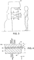
- FIG. 3 illustrates a machine 50 for carrying out the invention on human breasts.
- the machine is similar in many respects to X-ray machines familiar in the prior art for obtaining mammographic images used to detect breast cancer.
- a human breast is placed between two breast clamps or plates 52, typically made of or at least faced with a transparent plastic, which are then adjusted to compress the bulk of the breast to a thickness of about 2 cm.
- an X-ray source 54 is housed above the breast clamps 52, and an X-ray camera 56 or film is housed in the lower breast clamp.
- one of the breast clamps incorporates the illumination optics 32 of figure 2
- the other breast clamp incorporates the collection optics 34.
- the optics may be automatically driven to scan across the clamped breast, may be automatically driven or manually adjustable to be directed at a particular region of interest, or they may be of sufficient extent to cover a substantial portion of the clamped breast.
- the machine 50 may either include or not include X-ray facilities as described above. If X-ray facilities are included then X-ray image data may be used to direct operation of the Raman optics to study a particular part of a breast.
- the machine 50 preferably also includes means for spectral analysis of the collected Raman light, and computer apparatus for processing the results of the spectral analysis to present useful information to a clinician.
- the computer apparatus could be implemented to interpret the results of the spectral analysis in order to output data indicating the degree of presence of different chemical types of calcification in the probed breast tissue.
- Calcifications are found in many different biological tissues, forming both as natural products, e.g. in bones and teeth, and in soft tissues as a result of disease. Natural calcifications are present as a mineralization product in bone, and consist of the specific mineral hydroxyapatite. Pathological calcifications are associated with many medical conditions such as diabetes, breast cancer and crystals-associated osteoarthritis. The deposition of calcium crystals on cells induces detrimental cellular effects and speeds up the progression of the associated diseases.
- calcifications in mammographic images is a feature of particular diagnostic significance, as sometimes this may be the only marker of a malignant breast lesion.
- Mammography can detect small masses, areas of distortion, ill-defined densities and microcalcifications not detectable by physical examination. However, as this relies only on the morphology of the specimen, it has no definitive criteria for classifying benign and malignant calcifications. It has in fact been found that only 10-25% of mammographically detected lesions are found to be malignant upon needle biopsy.
- Microcalcifications can be divided into two types; type I, which consist of calcium oxalate dehydrate (COM), and type II deposits, which are composed of calcium phosphates, mainly calcium hydroxyapatite (HAP).
- type I which consist of calcium oxalate dehydrate (COM)
- type II deposits which are composed of calcium phosphates, mainly calcium hydroxyapatite (HAP).
- HAP calcium hydroxyapatite
- the methods and apparatus described herein may be used to measure the chemical make-up of lesions and calcifications non-invasively and in vivo, permitting a more simplistic decision for diagnosing breast lesions. This can be used to reduce patient trauma, time delay, and high medical costs associated with the biopsy of benign lesions.
- a Monte Carlo model was used to simulate the transport of illumination photons and Raman photons scattering within a turbid medium such as the body part 30 of figure 2 .
- the model was used to calculate the relative intensities of backscattered and forward scattered Raman photons as a function of their depth within the turbid medium. Briefly, both the elastically (illumination) and non-elastically (Raman) scattered photons were individually followed as they propagated through the medium in random walk-like fashion in three-dimensional space. A simplified assumption was made that in each step a photon propagated in a straight line over a distance t and thereafter its direction was fully randomised at the next scattering event.
- the propagation distance, t over which the photon direction is randomised, can be crudely approximated as the transport length of the scattering medium (I t ) ( Brenan C. and Hunter I., Journal of Raman Spectroscopy 27, p561, 1996 ) which is defined in a similar manner as the average distance photons must travel within the sample before deviating significantly from their original direction of propagation.
- the modelled sample body part 60 is illustrated in figure 4 .
- the sample body part was modelled as a uniform turbid medium apart from an intermediate-layer 66 having a different Raman signature to represent a tissue of interest, the intermediate layer having a thickness d2 with a top surface located at depth d1 .
- the bulk sample medium was located at depths z1 such that d1>z1>0 and d3>z1>(d1+d2), and the intermediate layer of a different Raman signature at depths z2 such that d1+d2 ⁇ z2 ⁇ d1.
- the parameters d2 and d3 were fixed at 0.5 mm and 4 mm respectively, and d1 was varied from 0 to 3.5 mm to represent different depths of the interlayer 66 within the bulk of the sample 60.
- the model assumed that all the illumination photons were first placed at a depth equal to the transport length lt and symmetrically distributed around the origin of the co-ordinate system x,y.
- the beam radius of the incident light r was 3 mm and the beam was given a uniform 'top-hat' intensity profile with all the photons having equal probability of being injected into the sample at any point within its cross-section.
- the Raman light was collected firstly at the top sample surface 62 from the illumination area of the incident light, and separately on the opposite side of the sample 64 symmetrically around the projection axis of the top collection/laser illumination area.
- the laser beam photons were propagated through the medium by translating each individual photon in a random direction by a step t . At each step there was a given probability that the photon would be converted to a Raman photon. The absorption of photons was assumed to be insignificant in this simulation.
- This parameter is expressed as optical density for the conversion of laser beam photons to Raman light. That is, for example, an optical density (OD) of 1 or 2 per 1 mm corresponds to the 10-fold or 100-fold decrease of the number of illumination photons through conversion to Raman photons, respectively, passing through an overall propagation distance of 1 mm.
- the optical density accounting for the conversion of illumination photons into Raman photons was set to 0.01 per millimetre.
- the number of Raman photons originating in the intermediate layer 66 and collected as backscattered photons at the upper surface 62, and transmitted photons at the lower surface 64, are shown in figure 5 .
- the dependence of the intensity of transmitted Raman photons exhibits only a weak dependence on the position of the intermediate layer within the sample.
- the corresponding Raman signal varies only by a factor of about 2.
- the absolute intensity of the Raman signal from the intermediate layer is only about 20-times lower than that of the bulk medium making detection relatively straightforward. Therefore the transmission geometry clearly provides a more representative sampling of the bulk of the body part interior than the conventional backscattering geometry, while permitting a satisfactory sensitivity.
- the model also reveals that an increase in sample body part thickness from 1 mm to 4 mm results in a 58% increase of the Raman signal detected in the backscattering geometry. In simplistic terms, this could be wrongly interpreted as extra Raman photons (amounting to 37 % of the overall Raman signal observed for 4 mm thick body part) being produced in the extra 3 mm thickness added to the top 1 mm sample layer. However, the model of a 4 mm-thick body part indicates that 88 % of Raman signal originates in the top 1 mm layer and only 12 % originates within the remaining 3 mm of body part thickness.
- the extra 3 mm of material not only contributes with extra production of Raman photons but also reduces the loss of Raman photons originated within the 1 mm-layer at the lower surface 64.
- the increase in backscattered Raman photons through the addition of a further 3 mm of sample is also accomplished by returning Raman photons originating near the upper surface back towards the upper surface from where they may emerge and be collected.
- some illumination photons are scattered back towards the upper surface 62 allowing them to originate still more Raman photons within the top 1 mm layer.
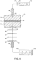
- a laser 78 was used to generate an illumination beam directed at a first surface region 80 of the sample using illumination optics, and light scattered through the whole thickness of the sample including the optical cell 74 and two layers of chicken breast 72 to a second surface region 82 was gathered using collection optics. The Raman components of the collected light were then analysed to determine the degree to which the material in the optical cell could be detected and identified.
- the illumination beam was generated using a temperature stabilised diode laser 78 suitable for Raman spectroscopy and operating at 827 nm (Micro Laser Systems, Inc, L4 830S-115-TE).
- the laser power at the first surface region was about 60 mW and the laser spot diameter at the first surface region was about 4 mm.
- the beam was spectrally purified by removing any residual amplified spontaneous emission components from its spectrum using two 830 nm Semrock (RTM) bandpass filters (84). These were slightly tilted to optimise throughput at the 827 nm laser wavelength.
- RTM Semrock
- the illumination optics were provided by a fibre optic probe 86 at which a bundle of seven core optical fibres and 26 outer ring fibres terminated. This probe was of the same construction as the probe used in the collection optics, described in more detail below.
- the light scattered through the sample to the second surface region 82 was collected using the following collection optics.
- Light emerging from the region was gathered by a 50 mm diameter lens 90 with a focal length of 60 mm.
- the gathered light was collimated and passed through a 50 mm diameter holographic notch filter 92 (830 nm, Kaiser Optical Systems, Inc) to suppress the elastically scattered component of light corresponding to the original laser frequency.
- the filter was also slightly tilted to optimise the suppression for the 827 nm elastic scatter.
- a second lens 94 identical to the first, was then used to image, with magnification 1:1, the sample interaction zone onto the front face of a fibre probe 96.
- the laser incident spot at the first surface region was positioned in such a way so that it coincided with the centre of the probe axis as projected through the imaging system onto the sample.
- a 25 mm diameter holographic notch filter, 830 nm, Kaiser Optical Systems, Inc. (98) and an edge filter, 830 nm, Semrock (99) were used just before the probe 96 to suppress any residual elastically scattered light that passed through the first holographic filter 92.
- the fibre probe 96 was comprised of 7 fibres placed tightly packed at the centre of the probe and 26 fibres distributed on a ring of 3 mm radius.
- the fibres were made of silica with a core diameter of 200 ⁇ m, cladding diameter of 230 ⁇ m and numerical aperture of 0.37. Sleeves were stripped on both ends for tighter packing of the fibres.
- the bundle was custom made by C Technologies Inc.
- the Raman spectra were collected using a deep depletion cooled CCD camera 102 by binning the signal from both sets of fibres into a single spectrum (full vertical chip binning). The Raman spectra are not corrected for the variation of detection system sensitivity across the active spectral range.
- Figure 7a shows spectra measured using the above arrangement when the optical cell was empty (110), when the optical cell was filled with HAP powder (112) and when the optical cell was filled with COM powder (114). These spectra are drawn with reference to the scale on the right hand axis, with additional arbitrary offsets to separate the spectra in the vertical direction. For reference, spectra taken using the same experimental set up but omitting the chicken breast tissue are shown for HAP powder (116) and COM powder (118). These reference spectra are drawn with reference to the scale on the left hand axis, again with additional vertical offsets to separate the spectra. The principal features of the pure HAP and COM spectra are clearly visible in the respective curves 112 and 114 of the full experiment.
- Figure 7b is a presentation of the HAP (120) and COM (122) spectra of figure 7a with the tissue-only spectrum (110) subtracted therefrom, again with pure HAP and COM spectra shown for reference purposes.
- figure 7c which is otherwise the same as figure 7b , shows the results of this experiment with the background subtracted HAP spectrum as 124 and the background subtracted COM spectrum as 126.
- a sample was prepared without using an optical cell. Instead, either COM or HAP powder was smeared on chicken breast tissue so as to present a layer of calcified material about 100 - 300 ⁇ m thick, between two layers of chicken breast tissue each about 16 mm thick.
- Figure 8a shows spectra taken using this sample using COM powder (130), HAP powder (132), and as a control background with no powder layer (134). The COM and HAP spectra with the background spectrum subtracted are shown in figure 8b as curves 136 and 138 respectively, with pure COM and Hap spectra shown for reference.
- the principal spectral features identifying these substances are still clearly visible.
- the sensitivity and penetration depth of the technique can be improved further by increasing the power of the incident light beam and the efficiency of the collection system.
- the incident light beam and consequently the first surface region may be enlarged, for example to a diameter of several centimetres, allowing incident light beam powers approaching 1 Watt to be used safely.
- the collection optics may be similarly scaled to collect as much of the transmitted light as possible, for example using imaging optics, a large fibre bundle, or both to cover an large second surface region.
- the illumination and collection optics can take a variety of forms.
- the illumination light may be projected onto the first surface region from wide range of distances, depending on the detailed circumstances of the application, using imaging optics or optical fibres.
Landscapes
- Health & Medical Sciences (AREA)
- Life Sciences & Earth Sciences (AREA)
- Physics & Mathematics (AREA)
- General Health & Medical Sciences (AREA)
- General Physics & Mathematics (AREA)
- Immunology (AREA)
- Pathology (AREA)
- Chemical & Material Sciences (AREA)
- Analytical Chemistry (AREA)
- Biochemistry (AREA)
- Toxicology (AREA)
- Engineering & Computer Science (AREA)
- Nuclear Medicine, Radiotherapy & Molecular Imaging (AREA)
- Heart & Thoracic Surgery (AREA)
- Spectroscopy & Molecular Physics (AREA)
- Biomedical Technology (AREA)
- Vascular Medicine (AREA)
- Medical Informatics (AREA)
- Molecular Biology (AREA)
- Surgery (AREA)
- Animal Behavior & Ethology (AREA)
- Hematology (AREA)
- Public Health (AREA)
- Veterinary Medicine (AREA)
- Biophysics (AREA)
- Food Science & Technology (AREA)
- Medicinal Chemistry (AREA)
- Investigating, Analyzing Materials By Fluorescence Or Luminescence (AREA)
- Credit Cards Or The Like (AREA)
- Optical Measuring Cells (AREA)
- Apparatus For Radiation Diagnosis (AREA)
Claims (14)
- Verfahren zur nicht-invasiven in vivo-Messung der Zusammensetzung von Verkalkungen, die in einem Gewebe innerhalb eines Teils (30) eines menschlichen oder tierischen Subjekts vorhanden sind, umfassend:Lenken von Strahlung in das Teil durch einen ersten äußeren Oberflächenbereich (40) des Teils;Sammeln eines Teils der Strahlung, der nach Vorwärtsstreuung durch das Teil an einem zweiten äußeren Oberflächenbereich (44) des Teils austritt;Erfassen, in der gesammelten Strahlung, von Eigenschaften der Strahlung, die von Raman-Streuung durch die Verkalkungen herrühren; undBestimmen eines Maßes der Zusammensetzung der Verkalkungen aus den Eigenschaften.
- Verfahren nach Anspruch 1, bei dem der zweite Oberflächenbereich (44) von dem ersten Oberflächenbereich so beabstandet ist, dass mindestens ein Teil des Gewebes direkt zwischen dem ersten und dem zweiten äußeren Oberflächenbereich liegt.
- Verfahren nach Anspruch 1 oder 2, bei dem sich zumindest während der Schritte des Lenkens und Sammelns der zweite Oberflächenbereich (44) auf einer dem ersten Oberflächenbereich (40) gegenüberliegenden Seite des Teils befindet.
- Verfahren nach Anspruch 1, bei dem das Messen der Zusammensetzung eine Messung mindestens eines Materials vom Typ I, Calciumoxalat, und eines Materials vom Typ II, Calciumphosphat oder Calciumhydroxyapatit, umfasst.
- Verfahren nach einem der vorhergehenden Ansprüche, bei dem der Körperteil eine Brust ist.
- Verfahren nach Anspruch 5, das ferner das Zusammendrücken der Brust zwischen gegenüberliegenden Klemmflächen umfasst, so dass die erste Außenfläche und die zweite Außenfläche der Brust durch die Klemmflächen aufeinander zu gedrückt werden.
- Verfahren nach einem der vorhergehenden Ansprüche, bei dem das Gewebe mindestens eines der folgenden umfasst: Knochen, Knorpel, Knochenmark, Gehirn, Nerven, Lipide, Blut, Zähne und Brustgewebe.
- Vorrichtung zur nicht-invasiven in-vivo-Messung der Zusammensetzung von Verkalkungen, die in einem Gewebe in einem menschlichen oder tierischen Subjekt vorhanden sind, umfassend:eine Beleuchtungsoptik (32), die eingerichtet ist, um Messlicht auf eine erste Oberfläche des Subjekts zu richten;eine Sammeloptik (34), die eingerichtet ist, um vorwärts gestreutes Licht von einer zweiten Oberfläche des Subjekts zu sammeln, so dass mindestens ein Teil des Gewebes zwischen der ersten und der zweiten Oberfläche liegt;eine Lichtquelle (36), die eingerichtet ist, um das Messlicht an die Beleuchtungsoptik zu liefern;einen Analysator (46), der eingerichtet ist, um das gesammelte Licht von der Sammeloptik zu empfangen und eine oder mehrere Raman-Spektralmerkmale des gesammelten Lichts zu bestimmen; undeinen Datenprozessor (48), der eingerichtet ist, um die bestimmten ein oder mehrere Raman-Spektralmerkmale zu empfangen und daraus einen oder mehrere Hinweise auf die Zusammensetzung der Verkalkungen abzuleiten.
- Vorrichtung nach Anspruch 8, die ferner eine Rückhaltevorrichtung umfasst, die eingerichtet ist, um die Bewegung mindestens eines Teils des Subjekts, der das Gewebe enthält, einzuschränken.
- Vorrichtung nach einem der Ansprüche 8 oder 9, die ferner eine Röntgenquelle und einen Röntgendetektor umfasst, die eingerichtet sind, um Merkmale des Gewebes zu bestimmen.
- Vorrichtung nach einem der Ansprüche 8 bis 10, die eingerichtet ist zum nicht-invasiven In-vivo-Messen der Zusammensetzung von verkalktem Gewebe in einer Brust eines menschlichen oder tierischen Subjekts, umfassend:eine Brusthalterung, die mindestens eine erste und eine zweite Haltefläche umfasst, die eingerichtet sind, in Konfrontation gebracht zu werden, um die Brust dazwischen zusammenzudrücken,wobei die Beleuchtungsoptik eingerichtet ist, um Strahlung in die Brust zu lenken, wenn sie in der Brusthalterung zusammengedrückt ist,wobei die Sammeloptik eingerichtet ist, um einen Teil der aus der Brust austretenden Strahlung zu sammeln, undwobei der Analysator eingerichtet ist, um in der gesammelten Strahlung Eigenschaften der Strahlung zu detektieren, die von der Raman-Streuung durch das verkalkte Gewebe herrühren.
- Vorrichtung nach Anspruch 11, bei der der Datenprozessor (48) eingerichtet ist, um aus den Merkmalen ein Maß für die Zusammensetzung des verkalkten Gewebes zu bestimmen.
- Vorrichtung nach Anspruch 11 oder 12, die so eingerichtet ist, dass sich das Gewebe zwischen der Beleuchtungsoptik (32) und der Sammeloptik (34) befindet.
- Vorrichtung nach Anspruch 13, bei dem die Beleuchtungsoptik eingerichtet ist, um Strahlung durch einen ersten Oberflächenbereich der Brust zu lenken, der der ersten Haltefläche gegenüberliegt, und die Sammeloptik eingerichtet ist, um einen Teil der Strahlung zu sammeln, die aus der Brust über einen zweiten Oberflächenbereich der Brust austritt, der der zweiten Haltefläche gegenüberliegt.
Applications Claiming Priority (3)
| Application Number | Priority Date | Filing Date | Title |
|---|---|---|---|
| GBGB0606891.0A GB0606891D0 (en) | 2006-04-05 | 2006-04-05 | Raman Analysis Of Pharmaceutical Tablets |
| GBGB0616376.0A GB0616376D0 (en) | 2006-04-05 | 2006-08-17 | Raman analysis of tissue |
| PCT/GB2007/001258 WO2007113570A1 (en) | 2006-04-05 | 2007-04-05 | Raman analysis of tissue |
Publications (2)
| Publication Number | Publication Date |
|---|---|
| EP2010042A1 EP2010042A1 (de) | 2009-01-07 |
| EP2010042B1 true EP2010042B1 (de) | 2021-05-26 |
Family
ID=36539406
Family Applications (4)
| Application Number | Title | Priority Date | Filing Date |
|---|---|---|---|
| EP06808690.9A Active EP1952129B1 (de) | 2005-11-25 | 2006-11-27 | Sicherheits-screening mittels raman-analyse |
| EP18209601.6A Active EP3477285B1 (de) | 2006-04-05 | 2007-04-05 | Ramananalyse |
| EP07732297.2A Revoked EP2002243B1 (de) | 2006-04-05 | 2007-04-05 | Ramananalyse |
| EP07732306.1A Active EP2010042B1 (de) | 2006-04-05 | 2007-04-05 | Raman-analyse von gewebe |
Family Applications Before (3)
| Application Number | Title | Priority Date | Filing Date |
|---|---|---|---|
| EP06808690.9A Active EP1952129B1 (de) | 2005-11-25 | 2006-11-27 | Sicherheits-screening mittels raman-analyse |
| EP18209601.6A Active EP3477285B1 (de) | 2006-04-05 | 2007-04-05 | Ramananalyse |
| EP07732297.2A Revoked EP2002243B1 (de) | 2006-04-05 | 2007-04-05 | Ramananalyse |
Country Status (8)
| Country | Link |
|---|---|
| US (3) | US7911604B2 (de) |
| EP (4) | EP1952129B1 (de) |
| JP (2) | JP2009538156A (de) |
| CN (2) | CN101460091B (de) |
| AU (2) | AU2007232354A1 (de) |
| CA (2) | CA2647730A1 (de) |
| GB (3) | GB0606891D0 (de) |
| WO (2) | WO2007113581A1 (de) |
Families Citing this family (56)
| Publication number | Priority date | Publication date | Assignee | Title |
|---|---|---|---|---|
| ES2174560T3 (es) * | 1999-08-27 | 2002-11-01 | Degussa | Negro de carbono de horno, procedimiento para su preparacion y su empleo. |
| GB0606891D0 (en) * | 2006-04-05 | 2006-05-17 | Council Cent Lab Res Councils | Raman Analysis Of Pharmaceutical Tablets |
| US8325337B2 (en) * | 2007-07-13 | 2012-12-04 | Purdue Research Foundation | Time resolved raman spectroscopy |
| SE531527C2 (sv) * | 2007-10-01 | 2009-05-12 | Bioresonator Ab | Förfarande vid och en anordning för opåverkad materialundersökning |
| EP3683218B1 (de) | 2007-12-07 | 2024-09-18 | Vertex Pharmaceuticals Incorporated | Feste formen von 3-(6-(1-(2,2-difluorbenzo[d][1,3]dioxol-5-yl)-cyclopropancarboxamido)-3-methylpyridin-2-yl)benzoesäure |
| EP2501288B1 (de) | 2009-11-19 | 2016-12-21 | Modulated Imaging Inc. | Verfahren und vorrichtung zur analyse trüber medien durch einzelelementerkennung mithilfe strukturierter beleuchtung |
| US20120092663A1 (en) * | 2010-10-14 | 2012-04-19 | Kull Linda S | Transmission raman spectroscopy analysis of seed composition |
| DE102011002181A1 (de) * | 2011-04-19 | 2012-10-25 | Bundesdruckerei Gmbh | Verfahren und Vorrichtung zur Überprüfung von Sicherheitsmerkmalen in Sicherheitsdokumenten |
| AU2012350656B2 (en) * | 2011-12-16 | 2015-04-30 | Glaxo Group Limited | Apparatus for testing samples using Raman radiation |
| NZ727015A (en) | 2012-01-25 | 2017-12-22 | Vertex Pharma | Formulations of 3-(6-(1-(2,2-difluorobenzo[d][1,3]dioxol-5-yl) cyclopropanecarboxamido)-3-methylpyridin-2-yl)benzoic acid |
| WO2013124164A1 (en) * | 2012-02-24 | 2013-08-29 | Paul Scherrer Institut | A system for non-invasively classification of different types of micro-calcifications in human tissue |
| CA2889489C (en) | 2012-11-07 | 2021-05-11 | David Cuccia | Efficient modulated imaging |
| CN105358946B (zh) * | 2013-02-14 | 2017-07-14 | 曾海山 | 用于光谱测量系统的校准的光学基准 |
| US9983136B2 (en) | 2013-05-27 | 2018-05-29 | Indian Institute Of Science | Method and an apparatus for obtaining sample specific signatures |
| US9606062B2 (en) * | 2013-05-27 | 2017-03-28 | Indian Institute Of Science | Method and a system for detection of hazardous chemicals in a non-metallic container |
| KR20150010392A (ko) * | 2013-07-19 | 2015-01-28 | 케이맥(주) | 결정화된 실리콘의 검사 방법 및 장치 |
| US20150022802A1 (en) * | 2013-07-22 | 2015-01-22 | Frederick Harold LONG | Spectroscopy detection system and method for material identification |
| AU2014349010C1 (en) * | 2013-11-12 | 2020-08-06 | Vertex Pharmaceuticals Incorporated | Process of preparing pharmaceutical compositions for the treatment of CFTR mediated diseases |
| CN103743717B (zh) * | 2013-12-03 | 2015-09-23 | 中国工程物理研究院化工材料研究所 | 炸药cl-20晶型定量分析拉曼特征区域确定方法 |
| CN104749158B (zh) * | 2013-12-27 | 2020-12-11 | 同方威视技术股份有限公司 | 珠宝玉石鉴定方法及装置 |
| US9295420B2 (en) | 2014-01-29 | 2016-03-29 | Hong Kong Applied Science and Technology Research Institute Company Limited | Transmission-reflectance swappable Raman probe for physiological detections |
| US10436716B2 (en) * | 2014-09-24 | 2019-10-08 | Smiths Detection, Inc. | Ubiquitous transmissive raman spectroscopy for stand-off detection |
| US10072984B2 (en) | 2014-10-02 | 2018-09-11 | Mks Technology, Inc. | Spectrometer |
| GB201503911D0 (en) | 2015-03-09 | 2015-04-22 | Renishaw Plc | Transmission raman spectroscopy |
| CN104730060A (zh) * | 2015-03-20 | 2015-06-24 | 扬州大学 | 一种体外简便模拟骨密度可控下降及快速检测方法 |
| US10288814B2 (en) | 2015-03-25 | 2019-05-14 | Board Of Regents Of The University Of Texas System | Variable spatial offset fiber optic probe for optical spectography and imaging |
| GB201511574D0 (en) | 2015-07-01 | 2015-08-12 | Stfc Science & Technology | Clinical thermometer |
| WO2017066399A1 (en) * | 2015-10-15 | 2017-04-20 | The Usa, As Represented By The Secretary Of The Navy | Trace-gas raman spectroscopy in functionalized waveguides |
| US10365229B2 (en) | 2015-12-31 | 2019-07-30 | Kaiser Optical Systems, Inc. | Real-time characterization of pharmaceutical tablet coatings using Raman spectroscopy |
| US11547365B2 (en) * | 2016-04-13 | 2023-01-10 | Koninklijke Philips N.V. | System and method for skin detection of a human subject |
| US11092494B1 (en) | 2016-05-31 | 2021-08-17 | MKS Technology | Spectrometer |
| GB201618260D0 (en) | 2016-10-28 | 2016-12-14 | Science And Tech Facilities Council The | Detection of pH |
| US10119916B2 (en) * | 2016-11-11 | 2018-11-06 | B&W Tek Llc | Light delivery and collection device for measuring Raman scattering of a sample |
| US10119917B2 (en) | 2016-11-11 | 2018-11-06 | B & W Tek LLC | Apparatus and method for bidirectional Raman spectroscopy |
| WO2018134980A1 (ja) | 2017-01-20 | 2018-07-26 | オリンパス株式会社 | 軟骨組織の分析装置 |
| CN110914675A (zh) | 2017-04-11 | 2020-03-24 | 瑞艾迪粒子系统有限责任公司 | 用于颗粒悬浮物的基于显微镜的图像获取和基于拉曼光谱的材料分析的液体池单元 |
| CN108398418B (zh) * | 2018-03-16 | 2020-12-04 | 华东理工大学 | 一种内参比表面增强拉曼测试试纸、制备方法与应用 |
| CN108577874B (zh) * | 2018-05-21 | 2021-09-17 | 达影医疗(中山)有限公司 | 乳腺摆位压迫装置及乳腺x线摄影系统 |
| JP7075285B2 (ja) * | 2018-05-29 | 2022-05-25 | 株式会社堀場製作所 | 薬剤分析に用いられる検量線設定方法 |
| CN109060766A (zh) * | 2018-09-27 | 2018-12-21 | 珠海彩晶光谱科技有限公司 | 一种基于表面增强拉曼光谱的体液药物浓度的测量方法和检测装置 |
| GB2572662B (en) | 2018-10-05 | 2020-06-03 | Res & Innovation Uk | Raman spectrometer |
| GB2581154B (en) | 2019-02-05 | 2022-09-28 | Colvistec Ag | Amorphous pharmaceutical compositions |
| EP3986248B1 (de) | 2019-06-19 | 2025-03-19 | Syddansk Universitet | System und verfahren zur raman-computertomografie (raman-ct) |
| GB201910801D0 (en) | 2019-07-29 | 2019-09-11 | Agilent Tech Lda Uk Limited | Raman analysis of pharmaceutical dosage forms |
| DE102019219949A1 (de) * | 2019-12-18 | 2021-06-24 | Robert Bosch Gmbh | Substrat |
| GB202004010D0 (en) | 2020-03-19 | 2020-05-06 | Res & Innovation Uk | Detection of water content in tissue |
| WO2021195471A1 (en) | 2020-03-26 | 2021-09-30 | Innovative Photonic Solutions, Inc. | Method for selection of raman excitation wavelengths in multi-source raman probe |
| GB2594980B (en) | 2020-05-14 | 2025-01-01 | Agilent Tech Lda Uk Limited | Spectral analysis of a sample |
| GB2596804A (en) | 2020-07-06 | 2022-01-12 | Agilent Tech Lda Uk Limited | Raman analysis of pharmaceutical dosage forms |
| US11304605B2 (en) * | 2020-07-20 | 2022-04-19 | 123IV, Inc. | Self-administered, non-invasive, transcutaneous viral detector |
| JP7270582B2 (ja) * | 2020-07-20 | 2023-05-10 | アンリツ株式会社 | 分光測定装置 |
| US11898959B2 (en) * | 2020-12-07 | 2024-02-13 | Harry Owen | Solids analysis using Raman spectroscopy |
| CN114460058B (zh) * | 2021-02-20 | 2025-07-22 | 海南聚能科技创新研究院有限公司 | 一种光谱仪检测装置 |
| US12279758B2 (en) * | 2021-09-27 | 2025-04-22 | Ai Biomed Corp. | Tissue detection systems and methods |
| US11974726B2 (en) | 2021-09-27 | 2024-05-07 | Ai Biomed Corp. | Tissue detection systems and methods |
| GB2615370B (en) | 2022-02-08 | 2025-03-26 | Res & Innovation Uk | Detection using SERS probes |
Citations (1)
| Publication number | Priority date | Publication date | Assignee | Title |
|---|---|---|---|---|
| US4570638A (en) * | 1983-10-14 | 1986-02-18 | Somanetics Corporation | Method and apparatus for spectral transmissibility examination and analysis |
Family Cites Families (113)
| Publication number | Priority date | Publication date | Assignee | Title |
|---|---|---|---|---|
| US3442591A (en) * | 1965-03-06 | 1969-05-06 | Hitachi Ltd | Apparatus for measuring the raman effect of samples of infinitesimal quantities |
| US3516744A (en) | 1966-05-20 | 1970-06-23 | Perkin Elmer Corp | Sampling arrangement for laser-raman systems |
| US3770350A (en) * | 1972-07-24 | 1973-11-06 | Bell Telephone Labor Inc | Method utilizing an optical fiber raman cell |
| US3909132A (en) | 1974-06-11 | 1975-09-30 | Allied Chem | Spectroscopic temperature measurement |
| JPS6058820B2 (ja) | 1979-07-31 | 1985-12-21 | 工業技術院長 | 透明物質の表面分析方法 |
| US4645340A (en) * | 1983-06-01 | 1987-02-24 | Boston University | Optically reflective sphere for efficient collection of Raman scattered light |
| AU565295B2 (en) * | 1983-10-13 | 1987-09-10 | Matsushita Electric Industrial Co., Ltd. | Fluid deflecting assembly |
| US5139025A (en) * | 1983-10-14 | 1992-08-18 | Somanetics Corporation | Method and apparatus for in vivo optical spectroscopic examination |
| DE3424108A1 (de) * | 1984-06-29 | 1986-01-09 | Bernhard Prof. Dr.-Ing. 4300 Essen Schrader | Probenanordnung zur spektrometrie, verfahren zur messung von lumineszenz und streuung und verwendung der probenanordnung |
| GB8514992D0 (en) * | 1985-06-13 | 1985-07-17 | British Nuclear Fuels Plc | Differentiation technique |
| US4784486A (en) * | 1987-10-06 | 1988-11-15 | Albion Instruments | Multi-channel molecular gas analysis by laser-activated Raman light scattering |
| US4945239A (en) * | 1989-03-29 | 1990-07-31 | Center For Innovative Technology | Early detection of breast cancer using transillumination |
| GB9002360D0 (en) * | 1990-02-02 | 1990-04-04 | De La Rue Co Plc | Ink composition and components thereof |
| GB9009132D0 (en) * | 1990-04-24 | 1990-06-20 | Gersan Ets | Method and apparatus for examining an object |
| US5261410A (en) * | 1991-02-07 | 1993-11-16 | Alfano Robert R | Method for determining if a tissue is a malignant tumor tissue, a benign tumor tissue, or a normal or benign tissue using Raman spectroscopy |
| EP0573535B1 (de) | 1991-02-26 | 2000-12-27 | Massachusetts Institute Of Technology | Molekularspektroskopieverfahren und -einrichtungen zur gewebediagnose |
| US5194913A (en) * | 1991-03-20 | 1993-03-16 | The United States Of America As Represented By The United States Department Of Energy | Fiber-optic apparatus and method for measurement of luminescence and raman scattering |
| US5506678A (en) * | 1992-02-24 | 1996-04-09 | Hewlett Packard Company | System for collecting weakly scattered electromagnetic radiation |
| JP3271304B2 (ja) * | 1992-06-30 | 2002-04-02 | 株式会社島津製作所 | 飛行時間形イオン散乱分光装置 |
| US5371368A (en) | 1992-07-23 | 1994-12-06 | Alfano; Robert R. | Ultrafast optical imaging of objects in a scattering medium |
| US5746210A (en) * | 1993-02-26 | 1998-05-05 | David A. Benaron | Device and method for detection, localization, and characterization of inhomogeneities in turbid media |
| US5565982A (en) * | 1994-05-31 | 1996-10-15 | Recon Exploration | Apparatus and method for time resolved spectroscopy |
| US5818047A (en) | 1994-08-20 | 1998-10-06 | Renishaw Plc | Detector for explosive substances |
| JP3295869B2 (ja) | 1994-09-08 | 2002-06-24 | 株式会社ニコン | ラマン分光測定方法 |
| US5625458A (en) * | 1994-11-10 | 1997-04-29 | Research Foundation Of City College Of New York | Method and system for imaging objects in turbid media using diffusive fermat photons |
| US5660181A (en) * | 1994-12-12 | 1997-08-26 | Physical Optics Corporation | Hybrid neural network and multiple fiber probe for in-depth 3-D mapping |
| US5919140A (en) * | 1995-02-21 | 1999-07-06 | Massachusetts Institute Of Technology | Optical imaging using time gated scattered light |
| US5615673A (en) * | 1995-03-27 | 1997-04-01 | Massachusetts Institute Of Technology | Apparatus and methods of raman spectroscopy for analysis of blood gases and analytes |
| BR9601329A (pt) * | 1995-04-14 | 1998-01-13 | Fuji Xerox Co Ltd | Rolo transportador de cinta e aparelho formador de imagem |
| US5999836A (en) * | 1995-06-06 | 1999-12-07 | Nelson; Robert S. | Enhanced high resolution breast imaging device and method utilizing non-ionizing radiation of narrow spectral bandwidth |
| US5636633A (en) * | 1995-08-09 | 1997-06-10 | Rio Grande Medical Technologies, Inc. | Diffuse reflectance monitoring apparatus |
| US5760399A (en) | 1995-10-02 | 1998-06-02 | Foss Nirsystems, Inc. | Measurement of transmission spectra of pharmaceutical tablets |
| JPH09127001A (ja) | 1995-10-31 | 1997-05-16 | Ajinomoto Co Inc | 密封材料の非破壊検査法 |
| SE513163C2 (sv) | 1995-12-20 | 2000-07-17 | Astrazeneca Ab | Anordning och metod för spektrometri |
| JPH09184809A (ja) | 1995-12-30 | 1997-07-15 | Koyo Ozaki | 散乱光測定装置 |
| GB9609793D0 (en) * | 1996-05-10 | 1996-07-17 | Ciba Geigy Ag | Pigment compositions |
| US5866430A (en) | 1996-06-13 | 1999-02-02 | Grow; Ann E. | Raman optrode processes and devices for detection of chemicals and microorganisms |
| US5842995A (en) | 1996-06-28 | 1998-12-01 | Board Of Regents, The Univerisity Of Texas System | Spectroscopic probe for in vivo measurement of raman signals |
| US5873831A (en) * | 1997-03-13 | 1999-02-23 | The University Of Utah Technology Transfer Office | Method and system for measurement of macular carotenoid levels |
| JP2002510395A (ja) * | 1997-07-02 | 2002-04-02 | スペクトラ コード インコーポレイテッド | 高速同定ラマンシステム |
| GB2328016B (en) | 1997-08-08 | 2001-04-25 | Pfizer Ltd | Spectrophotometric analysis |
| SE9704873D0 (sv) | 1997-12-23 | 1997-12-23 | Astra Ab | Sampling apparatus |
| WO2000001295A1 (en) * | 1998-07-07 | 2000-01-13 | Lightouch Medical, Inc. | Tissue modulation process for quantitative noninvasive in vivo spectroscopic analysis of tissues |
| SE9802690D0 (sv) | 1998-08-07 | 1998-08-07 | Astra Ab | Mixing apparatus |
| GB9819732D0 (en) | 1998-09-11 | 1998-11-04 | Renishaw Plc | Tool conditioning monitoring |
| WO2000020843A1 (en) | 1998-10-07 | 2000-04-13 | Ecole Polytechnique Federale De Lausanne (Epfl) | Method and apparatus for measuring locally and superficially the scattering and absorption properties of turbid media |
| US6352502B1 (en) | 1998-12-03 | 2002-03-05 | Lightouch Medical, Inc. | Methods for obtaining enhanced spectroscopic information from living tissue, noninvasive assessment of skin condition and detection of skin abnormalities |
| SE9903423D0 (sv) | 1999-09-22 | 1999-09-22 | Astra Ab | New measuring technique |
| WO2001052739A1 (en) | 2000-01-21 | 2001-07-26 | Flock Stephen T | Optical measurements of bone composition |
| SE0000314D0 (sv) * | 2000-01-31 | 2000-01-31 | Astrazeneca Ab | Apparatus and method for analysing |
| SE0000522D0 (sv) | 2000-02-17 | 2000-02-17 | Astrazeneca Ab | Mixing apparatus |
| US6610351B2 (en) * | 2000-04-12 | 2003-08-26 | Quantag Systems, Inc. | Raman-active taggants and their recognition |
| AU2001272003A1 (en) | 2000-07-13 | 2002-02-05 | Virginia Commonwealth University | Use of ultraviolet, near-ultraviolet and near infrared resonance raman spectroscopy and fluorescence spectroscopy for tissue interrogation of shock states, critical illnesses, and other disease states |
| JP2002085385A (ja) | 2000-09-21 | 2002-03-26 | Sadako Honda | 血糖値の測定方法および測定装置 |
| IL138683A0 (en) * | 2000-09-25 | 2001-10-31 | Vital Medical Ltd | Apparatus and method for monitoring tissue vitality parameters |
| JP3836430B2 (ja) * | 2000-10-04 | 2006-10-25 | 東京瓦斯株式会社 | 同位体標識の非破壊読取方法 |
| SE0100283D0 (sv) | 2001-01-31 | 2001-01-31 | Astrazeneca Ab | Sampling apparatus |
| US6925514B1 (en) * | 2001-03-30 | 2005-08-02 | Agere Systems Inc. | Multi-protocol bus system and method of operation thereof |
| US6954667B2 (en) * | 2001-06-28 | 2005-10-11 | Chemimage Corporation | Method for Raman chemical imaging and characterization of calcification in tissue |
| JP2003010189A (ja) | 2001-07-04 | 2003-01-14 | Communication Research Laboratory | 生体機能情報撮像装置 |
| KR100976784B1 (ko) | 2001-09-12 | 2010-08-19 | 게르잔 에스테블리쉬먼트 | 다이아몬드 검사 |
| US6610977B2 (en) * | 2001-10-01 | 2003-08-26 | Lockheed Martin Corporation | Security system for NBC-safe building |
| IL161729A0 (en) | 2001-11-06 | 2005-11-20 | C I Systems Ltd | In-line spectroscopy for process monitoring |
| US6825928B2 (en) * | 2001-12-19 | 2004-11-30 | Wisconsin Alumni Research Foundation | Depth-resolved fluorescence instrument |
| US6975891B2 (en) * | 2001-12-21 | 2005-12-13 | Nir Diagnostics Inc. | Raman spectroscopic system with integrating cavity |
| US6873868B2 (en) | 2001-12-31 | 2005-03-29 | Infraredx, Inc. | Multi-fiber catheter probe arrangement for tissue analysis or treatment |
| US6654118B2 (en) * | 2002-02-04 | 2003-11-25 | Ortho-Mcneil Pharmaceutical, Inc. | Method and apparatus for obtaining molecular data from a pharmaceutical specimen |
| CA2418399A1 (en) * | 2002-02-11 | 2003-08-11 | Bayer Healthcare, Llc | Non-invasive system for the determination of analytes in body fluids |
| EP1475037B1 (de) | 2002-02-14 | 2012-09-12 | Toshinori Kato | Gerät zur beurteilung einer biologischen funktion |
| US6919556B1 (en) * | 2002-02-22 | 2005-07-19 | Monocle Technologies, Inc. | System and method for monitoring and evaluating solid and semi-solid materials |
| WO2003073082A1 (en) | 2002-02-28 | 2003-09-04 | Erasmus Universiteit Rotterdam | Depth selective ph measurement and uv exposure measurement |
| SE0200782D0 (sv) | 2002-03-14 | 2002-03-14 | Astrazeneca Ab | Method of analysing a pharmaceutical sample |
| US7647092B2 (en) | 2002-04-05 | 2010-01-12 | Massachusetts Institute Of Technology | Systems and methods for spectroscopy of biological tissue |
| US7197562B2 (en) | 2002-04-05 | 2007-03-27 | Infocus Corporation | Projector device management system |
| IL151745A (en) * | 2002-09-12 | 2007-10-31 | Uzi Sharon | Explosive detection and detection system |
| US8088628B2 (en) * | 2002-09-30 | 2012-01-03 | Intel Corporation | Stimulated and coherent anti-stokes raman spectroscopic methods for the detection of molecules |
| US20040142484A1 (en) | 2002-09-30 | 2004-07-22 | Intel Corporation | Spectroscopic analysis system and method |
| CA2501098C (en) * | 2002-10-23 | 2014-04-08 | Palomar Medical Technologies, Inc. | Phototreatment device for use with coolants and topical substances |
| EP1567852B1 (de) | 2002-12-02 | 2007-06-06 | River Diagnostics B.V. | Verwendung von hochwellenzahl-ramanspektroskopie zur messung von gewebe |
| US6897951B2 (en) * | 2003-02-14 | 2005-05-24 | Raman Systems, Inc. | Probe assemblies for Raman spectroscopy |
| JP4136704B2 (ja) | 2003-02-19 | 2008-08-20 | 株式会社島津製作所 | 光計測装置用のプローブとそれを用いたマルチチャンネル光計測装置 |
| JP2004271220A (ja) | 2003-03-05 | 2004-09-30 | Toshiba Ceramics Co Ltd | 石英ガラスの評価装置及び方法 |
| EP2301439A1 (de) | 2003-03-05 | 2011-03-30 | InfraReDx, Inc. | Kathetersondenanordnung für Gewebeanalyse mittels Strahlungsenergieabgabe und Strahlungsenergiesammlung |
| JP2004294150A (ja) | 2003-03-26 | 2004-10-21 | Univ Waseda | 分光分析装置及び分光分析法 |
| US7110109B2 (en) * | 2003-04-18 | 2006-09-19 | Ahura Corporation | Raman spectroscopy system and method and specimen holder therefor |
| WO2004097365A2 (en) | 2003-04-30 | 2004-11-11 | Mcgill University | Method and system for measuring lactate levels in vivo |
| AU2003284845A1 (en) * | 2003-05-15 | 2004-12-03 | Alexei Alexeevich Agibalov | Method for forming a database for determining biological agents and chemical substances |
| US7242469B2 (en) * | 2003-05-27 | 2007-07-10 | Opto Trace Technologies, Inc. | Applications of Raman scattering probes |
| RU2269116C2 (ru) * | 2003-06-18 | 2006-01-27 | Глеб Игоревич Андреев | Устройство для формирования базы данных для определения биологических агентов и химических веществ |
| JP4388318B2 (ja) * | 2003-06-27 | 2009-12-24 | オリンパス株式会社 | 画像処理装置 |
| US7396650B2 (en) * | 2003-06-27 | 2008-07-08 | Commissariat A L'energie Atomique | Method for dosing a biological or chemical sample |
| WO2005004714A1 (en) | 2003-07-01 | 2005-01-20 | The Regents Of The University Of Michigan | Method and apparatus for diagnosing bone tissue conditions |
| JP2005070009A (ja) | 2003-08-28 | 2005-03-17 | Toyota Motor Corp | 分光分析装置 |
| US20060249423A1 (en) | 2003-11-28 | 2006-11-09 | Mika Reijonen | Method and apparatus to identify and separate medicinal preparations and dosages thereof |
| US7148963B2 (en) | 2003-12-10 | 2006-12-12 | Kaiser Optical Systems | Large-collection-area optical probe |
| US7697576B2 (en) * | 2004-05-05 | 2010-04-13 | Chem Image Corporation | Cytological analysis by raman spectroscopic imaging |
| CN1584555A (zh) | 2004-06-01 | 2005-02-23 | 浙江大学 | 一种基于低分辨拉曼光谱的石油产品质量快速测定仪 |
| US7796243B2 (en) | 2004-06-09 | 2010-09-14 | National Research Council Of Canada | Detection and monitoring of changes in mineralized tissues or calcified deposits by optical coherence tomography and Raman spectroscopy |
| WO2006005022A2 (en) * | 2004-06-30 | 2006-01-12 | Chemimage Corporation | Dynamic chemical imaging of biological cells and other subjects |
| EP1766351A4 (de) * | 2004-06-30 | 2009-12-02 | Chemimage Corp | Multimodales verfahren zur identifizierung von gefährlichen mitteln |
| WO2006083316A2 (en) * | 2004-06-30 | 2006-08-10 | Chemimage Corporation | Multipoint method for identifying hazardous agents |
| US7269245B2 (en) * | 2004-07-30 | 2007-09-11 | Bruker Axs, Inc. | Combinatorial screening system and X-ray diffraction and Raman spectroscopy |
| GB0426993D0 (en) | 2004-12-09 | 2005-01-12 | Council Cent Lab Res Councils | Apparatus for depth-selective raman spectroscopy |
| WO2006078980A2 (en) * | 2005-01-20 | 2006-07-27 | Chemimage Corporation | Method for raman computer tomography imaging spectroscopy |
| JP4595571B2 (ja) * | 2005-02-04 | 2010-12-08 | セイコーエプソン株式会社 | 顕微ラマン分光装置及び顕微ラマン分光測定方法 |
| US8452365B2 (en) * | 2005-05-25 | 2013-05-28 | Bayer Healthcare Llc | Methods of using Raman spectral information in determining analyte concentrations |
| WO2007040589A1 (en) | 2005-09-16 | 2007-04-12 | The Regents Of The University Of Michigan | Method and system for measuring sub-surface composition of a sample |
| WO2007060467A1 (en) | 2005-11-25 | 2007-05-31 | The Science And Technology Facilities Council | Security screening using raman analysis |
| GB0606891D0 (en) | 2006-04-05 | 2006-05-17 | Council Cent Lab Res Councils | Raman Analysis Of Pharmaceutical Tablets |
| WO2007113570A1 (en) | 2006-04-05 | 2007-10-11 | The Science And Technology Facilities Council | Raman analysis of tissue |
| US7603151B2 (en) * | 2006-08-22 | 2009-10-13 | Bayer Healthcare Llc | Non-invasive methods of using spectral information in determining analyte concentrations |
| CA2661952A1 (en) | 2006-08-22 | 2008-02-28 | Bayer Healthcare Llc | Non-invasive methods of using spectral information in determining analyte concentrations |
| JP4862730B2 (ja) * | 2007-04-05 | 2012-01-25 | コニカミノルタセンシング株式会社 | 脈波データ解析方法、システム、プログラム |
-
2006
- 2006-04-05 GB GBGB0606891.0A patent/GB0606891D0/en not_active Ceased
- 2006-08-17 GB GBGB0616376.0A patent/GB0616376D0/en not_active Ceased
- 2006-09-21 GB GB0618635A patent/GB2432661A/en active Pending
- 2006-11-27 EP EP06808690.9A patent/EP1952129B1/de active Active
- 2006-11-27 US US12/085,346 patent/US7911604B2/en active Active
-
2007
- 2007-04-05 JP JP2009503653A patent/JP2009538156A/ja active Pending
- 2007-04-05 AU AU2007232354A patent/AU2007232354A1/en not_active Abandoned
- 2007-04-05 US US12/083,073 patent/US8085396B2/en active Active
- 2007-04-05 CA CA002647730A patent/CA2647730A1/en not_active Abandoned
- 2007-04-05 EP EP18209601.6A patent/EP3477285B1/de active Active
- 2007-04-05 CN CN2007800207096A patent/CN101460091B/zh not_active Expired - Fee Related
- 2007-04-05 EP EP07732297.2A patent/EP2002243B1/de not_active Revoked
- 2007-04-05 US US12/225,928 patent/US8259902B2/en active Active
- 2007-04-05 WO PCT/GB2007/001289 patent/WO2007113581A1/en not_active Ceased
- 2007-04-05 WO PCT/GB2007/001249 patent/WO2007113566A2/en not_active Ceased
- 2007-04-05 EP EP07732306.1A patent/EP2010042B1/de active Active
- 2007-04-05 JP JP2009503651A patent/JP2009536317A/ja active Pending
- 2007-04-05 AU AU2007232350A patent/AU2007232350A1/en not_active Abandoned
- 2007-04-05 CN CNA2007800207908A patent/CN101460831A/zh active Pending
- 2007-04-05 CA CA002648228A patent/CA2648228A1/en not_active Abandoned
Patent Citations (1)
| Publication number | Priority date | Publication date | Assignee | Title |
|---|---|---|---|---|
| US4570638A (en) * | 1983-10-14 | 1986-02-18 | Somanetics Corporation | Method and apparatus for spectral transmissibility examination and analysis |
Also Published As
| Publication number | Publication date |
|---|---|
| EP1952129B1 (de) | 2021-10-27 |
| EP2010042A1 (de) | 2009-01-07 |
| JP2009536317A (ja) | 2009-10-08 |
| EP2002243A2 (de) | 2008-12-17 |
| AU2007232354A1 (en) | 2007-10-11 |
| CA2648228A1 (en) | 2007-10-11 |
| US8085396B2 (en) | 2011-12-27 |
| CA2647730A1 (en) | 2007-10-11 |
| US7911604B2 (en) | 2011-03-22 |
| EP1952129A1 (de) | 2008-08-06 |
| JP2009538156A (ja) | 2009-11-05 |
| WO2007113566A3 (en) | 2007-11-29 |
| CN101460831A (zh) | 2009-06-17 |
| CN101460091A (zh) | 2009-06-17 |
| WO2007113566A2 (en) | 2007-10-11 |
| AU2007232350A1 (en) | 2007-10-11 |
| EP2002243B1 (de) | 2019-04-03 |
| WO2007113581A1 (en) | 2007-10-11 |
| GB0606891D0 (en) | 2006-05-17 |
| GB0616376D0 (en) | 2006-09-27 |
| US8259902B2 (en) | 2012-09-04 |
| EP3477285B1 (de) | 2025-04-23 |
| GB0618635D0 (en) | 2006-11-01 |
| EP3477285A1 (de) | 2019-05-01 |
| GB2432661A (en) | 2007-05-30 |
| US20090238333A1 (en) | 2009-09-24 |
| US20090141271A1 (en) | 2009-06-04 |
| US20090244533A1 (en) | 2009-10-01 |
| CN101460091B (zh) | 2011-12-14 |
Similar Documents
| Publication | Publication Date | Title |
|---|---|---|
| EP2010042B1 (de) | Raman-analyse von gewebe | |
| US11656448B2 (en) | Method and apparatus for quantitative hyperspectral fluorescence and reflectance imaging for surgical guidance | |
| Matousek et al. | Recent advances in the development of Raman spectroscopy for deep non‐invasive medical diagnosis | |
| Taroni et al. | Time-resolved optical mammography between 637 and 985 nm: clinical study on the detection and identification of breast lesions | |
| Kallaway et al. | Advances in the clinical application of Raman spectroscopy for cancer diagnostics | |
| Grosenick et al. | Time-domain scanning optical mammography: I. Recording and assessment of mammograms of 154 patients | |
| CN103635131B (zh) | 对相关组织样本进行光学分析的设备 | |
| EP1831673B1 (de) | Raman-spektralanalyse von unter der oberfläche liegenden geweben und flüssigkeiten | |
| Esmonde-White et al. | Fiber-optic Raman spectroscopy of joint tissues | |
| US20070073156A1 (en) | Combined visual-optic and passive infra-red technologies and the corresponding systems for detection and identification of skin cancer precursors, nevi and tumors for early diagnosis | |
| CN104067313B (zh) | 成像装置 | |
| WO2007113570A1 (en) | Raman analysis of tissue | |
| US12560793B2 (en) | Method and apparatus for quantitative hyperspectral fluorescence and reflectance imaging for surgical guidance | |
| WO2013132400A1 (en) | Apparatus for determining a property of a tissue | |
| CA2467407C (en) | Optical transillumination and reflectance spectroscopy to quantify disease risk | |
| Rinneberg et al. | Scanning time-domain optical mammography: detection and characterization of breast tumors in vivo | |
| Ghita et al. | Exploring the effect of laser excitation wavelength on signal recovery with deep tissue transmission Raman spectroscopy | |
| US20060089553A1 (en) | Method and apparatus for investigating histology of epithelial tissue | |
| WO2012127378A1 (en) | An apparatus for optical analysis of an associated tissue sample | |
| Abd Ghani et al. | VIS–NIR spectral signature and quantitative analysis of HeLa and DU145 cell line | |
| Taroni et al. | Multi-wavelength time domain optical mammography | |
| Taroni et al. | Time Domain Multi-Wavelength Diffuse Optics for Breast Cancer Management | |
| Fullwood | Raman spectroscopy for rapid diagnosis of lymphomas and metastatic lesions found in lymph nodes | |
| Canfell et al. | Real-time devices for the screening and diagnosis of cervical neoplasia | |
| Matousek | Subsurface Raman Spectroscopy in Turbid Media |
Legal Events
| Date | Code | Title | Description |
|---|---|---|---|
| PUAI | Public reference made under article 153(3) epc to a published international application that has entered the european phase |
Free format text: ORIGINAL CODE: 0009012 |
|
| 17P | Request for examination filed |
Effective date: 20081027 |
|
| AK | Designated contracting states |
Kind code of ref document: A1 Designated state(s): AT BE BG CH CY CZ DE DK EE ES FI FR GB GR HU IE IS IT LI LT LU LV MC MT NL PL PT RO SE SI SK TR |
|
| AX | Request for extension of the european patent |
Extension state: AL BA HR MK RS |
|
| 17Q | First examination report despatched |
Effective date: 20090525 |
|
| DAX | Request for extension of the european patent (deleted) | ||
| RAP1 | Party data changed (applicant data changed or rights of an application transferred) |
Owner name: UNITED KINGDOM RESEARCH AND INNOVATION |
|
| STAA | Information on the status of an ep patent application or granted ep patent |
Free format text: STATUS: EXAMINATION IS IN PROGRESS |
|
| RIC1 | Information provided on ipc code assigned before grant |
Ipc: A61B 5/00 20060101AFI20201109BHEP Ipc: G07D 7/1205 20160101ALI20201109BHEP Ipc: G01N 21/65 20060101ALI20201109BHEP |
|
| GRAP | Despatch of communication of intention to grant a patent |
Free format text: ORIGINAL CODE: EPIDOSNIGR1 |
|
| STAA | Information on the status of an ep patent application or granted ep patent |
Free format text: STATUS: GRANT OF PATENT IS INTENDED |
|
| INTG | Intention to grant announced |
Effective date: 20210104 |
|
| INTG | Intention to grant announced |
Effective date: 20210113 |
|
| GRAS | Grant fee paid |
Free format text: ORIGINAL CODE: EPIDOSNIGR3 |
|
| GRAA | (expected) grant |
Free format text: ORIGINAL CODE: 0009210 |
|
| STAA | Information on the status of an ep patent application or granted ep patent |
Free format text: STATUS: THE PATENT HAS BEEN GRANTED |
|
| AK | Designated contracting states |
Kind code of ref document: B1 Designated state(s): AT BE BG CH CY CZ DE DK EE ES FI FR GB GR HU IE IS IT LI LT LU LV MC MT NL PL PT RO SE SI SK TR |
|
| REG | Reference to a national code |
Ref country code: GB Ref legal event code: FG4D |
|
| REG | Reference to a national code |
Ref country code: CH Ref legal event code: EP |
|
| REG | Reference to a national code |
Ref country code: DE Ref legal event code: R096 Ref document number: 602007061142 Country of ref document: DE |
|
| REG | Reference to a national code |
Ref country code: AT Ref legal event code: REF Ref document number: 1395378 Country of ref document: AT Kind code of ref document: T Effective date: 20210615 |
|
| REG | Reference to a national code |
Ref country code: IE Ref legal event code: FG4D |
|
| REG | Reference to a national code |
Ref country code: LT Ref legal event code: MG9D |
|
| REG | Reference to a national code |
Ref country code: AT Ref legal event code: MK05 Ref document number: 1395378 Country of ref document: AT Kind code of ref document: T Effective date: 20210526 |
|
| PG25 | Lapsed in a contracting state [announced via postgrant information from national office to epo] |
Ref country code: BG Free format text: LAPSE BECAUSE OF FAILURE TO SUBMIT A TRANSLATION OF THE DESCRIPTION OR TO PAY THE FEE WITHIN THE PRESCRIBED TIME-LIMIT Effective date: 20210826 Ref country code: AT Free format text: LAPSE BECAUSE OF FAILURE TO SUBMIT A TRANSLATION OF THE DESCRIPTION OR TO PAY THE FEE WITHIN THE PRESCRIBED TIME-LIMIT Effective date: 20210526 Ref country code: FI Free format text: LAPSE BECAUSE OF FAILURE TO SUBMIT A TRANSLATION OF THE DESCRIPTION OR TO PAY THE FEE WITHIN THE PRESCRIBED TIME-LIMIT Effective date: 20210526 Ref country code: LT Free format text: LAPSE BECAUSE OF FAILURE TO SUBMIT A TRANSLATION OF THE DESCRIPTION OR TO PAY THE FEE WITHIN THE PRESCRIBED TIME-LIMIT Effective date: 20210526 |
|
| REG | Reference to a national code |
Ref country code: NL Ref legal event code: MP Effective date: 20210526 |
|
| PG25 | Lapsed in a contracting state [announced via postgrant information from national office to epo] |
Ref country code: GR Free format text: LAPSE BECAUSE OF FAILURE TO SUBMIT A TRANSLATION OF THE DESCRIPTION OR TO PAY THE FEE WITHIN THE PRESCRIBED TIME-LIMIT Effective date: 20210827 Ref country code: LV Free format text: LAPSE BECAUSE OF FAILURE TO SUBMIT A TRANSLATION OF THE DESCRIPTION OR TO PAY THE FEE WITHIN THE PRESCRIBED TIME-LIMIT Effective date: 20210526 Ref country code: IS Free format text: LAPSE BECAUSE OF FAILURE TO SUBMIT A TRANSLATION OF THE DESCRIPTION OR TO PAY THE FEE WITHIN THE PRESCRIBED TIME-LIMIT Effective date: 20210926 Ref country code: SE Free format text: LAPSE BECAUSE OF FAILURE TO SUBMIT A TRANSLATION OF THE DESCRIPTION OR TO PAY THE FEE WITHIN THE PRESCRIBED TIME-LIMIT Effective date: 20210526 Ref country code: PT Free format text: LAPSE BECAUSE OF FAILURE TO SUBMIT A TRANSLATION OF THE DESCRIPTION OR TO PAY THE FEE WITHIN THE PRESCRIBED TIME-LIMIT Effective date: 20210927 Ref country code: PL Free format text: LAPSE BECAUSE OF FAILURE TO SUBMIT A TRANSLATION OF THE DESCRIPTION OR TO PAY THE FEE WITHIN THE PRESCRIBED TIME-LIMIT Effective date: 20210526 |
|
| PG25 | Lapsed in a contracting state [announced via postgrant information from national office to epo] |
Ref country code: NL Free format text: LAPSE BECAUSE OF FAILURE TO SUBMIT A TRANSLATION OF THE DESCRIPTION OR TO PAY THE FEE WITHIN THE PRESCRIBED TIME-LIMIT Effective date: 20210526 |
|
| PG25 | Lapsed in a contracting state [announced via postgrant information from national office to epo] |
Ref country code: RO Free format text: LAPSE BECAUSE OF FAILURE TO SUBMIT A TRANSLATION OF THE DESCRIPTION OR TO PAY THE FEE WITHIN THE PRESCRIBED TIME-LIMIT Effective date: 20210526 Ref country code: ES Free format text: LAPSE BECAUSE OF FAILURE TO SUBMIT A TRANSLATION OF THE DESCRIPTION OR TO PAY THE FEE WITHIN THE PRESCRIBED TIME-LIMIT Effective date: 20210526 Ref country code: SK Free format text: LAPSE BECAUSE OF FAILURE TO SUBMIT A TRANSLATION OF THE DESCRIPTION OR TO PAY THE FEE WITHIN THE PRESCRIBED TIME-LIMIT Effective date: 20210526 Ref country code: DK Free format text: LAPSE BECAUSE OF FAILURE TO SUBMIT A TRANSLATION OF THE DESCRIPTION OR TO PAY THE FEE WITHIN THE PRESCRIBED TIME-LIMIT Effective date: 20210526 Ref country code: CZ Free format text: LAPSE BECAUSE OF FAILURE TO SUBMIT A TRANSLATION OF THE DESCRIPTION OR TO PAY THE FEE WITHIN THE PRESCRIBED TIME-LIMIT Effective date: 20210526 Ref country code: EE Free format text: LAPSE BECAUSE OF FAILURE TO SUBMIT A TRANSLATION OF THE DESCRIPTION OR TO PAY THE FEE WITHIN THE PRESCRIBED TIME-LIMIT Effective date: 20210526 |
|
| REG | Reference to a national code |
Ref country code: DE Ref legal event code: R097 Ref document number: 602007061142 Country of ref document: DE |
|
| PLBE | No opposition filed within time limit |
Free format text: ORIGINAL CODE: 0009261 |
|
| STAA | Information on the status of an ep patent application or granted ep patent |
Free format text: STATUS: NO OPPOSITION FILED WITHIN TIME LIMIT |
|
| 26N | No opposition filed |
Effective date: 20220301 |
|
| PG25 | Lapsed in a contracting state [announced via postgrant information from national office to epo] |
Ref country code: IS Free format text: LAPSE BECAUSE OF FAILURE TO SUBMIT A TRANSLATION OF THE DESCRIPTION OR TO PAY THE FEE WITHIN THE PRESCRIBED TIME-LIMIT Effective date: 20210926 |
|
| PG25 | Lapsed in a contracting state [announced via postgrant information from national office to epo] |
Ref country code: IT Free format text: LAPSE BECAUSE OF FAILURE TO SUBMIT A TRANSLATION OF THE DESCRIPTION OR TO PAY THE FEE WITHIN THE PRESCRIBED TIME-LIMIT Effective date: 20210526 |
|
| REG | Reference to a national code |
Ref country code: DE Ref legal event code: R119 Ref document number: 602007061142 Country of ref document: DE |
|
| REG | Reference to a national code |
Ref country code: CH Ref legal event code: PL |
|
| REG | Reference to a national code |
Ref country code: BE Ref legal event code: MM Effective date: 20220430 |
|
| PG25 | Lapsed in a contracting state [announced via postgrant information from national office to epo] |
Ref country code: FR Free format text: LAPSE BECAUSE OF NON-PAYMENT OF DUE FEES Effective date: 20220430 Ref country code: DE Free format text: LAPSE BECAUSE OF NON-PAYMENT OF DUE FEES Effective date: 20221103 Ref country code: CH Free format text: LAPSE BECAUSE OF NON-PAYMENT OF DUE FEES Effective date: 20220430 Ref country code: MC Free format text: LAPSE BECAUSE OF FAILURE TO SUBMIT A TRANSLATION OF THE DESCRIPTION OR TO PAY THE FEE WITHIN THE PRESCRIBED TIME-LIMIT Effective date: 20210526 Ref country code: LU Free format text: LAPSE BECAUSE OF NON-PAYMENT OF DUE FEES Effective date: 20220405 Ref country code: LI Free format text: LAPSE BECAUSE OF NON-PAYMENT OF DUE FEES Effective date: 20220430 |
|
| PG25 | Lapsed in a contracting state [announced via postgrant information from national office to epo] |
Ref country code: BE Free format text: LAPSE BECAUSE OF NON-PAYMENT OF DUE FEES Effective date: 20220430 |
|
| PG25 | Lapsed in a contracting state [announced via postgrant information from national office to epo] |
Ref country code: IE Free format text: LAPSE BECAUSE OF NON-PAYMENT OF DUE FEES Effective date: 20220405 |
|
| PG25 | Lapsed in a contracting state [announced via postgrant information from national office to epo] |
Ref country code: HU Free format text: LAPSE BECAUSE OF FAILURE TO SUBMIT A TRANSLATION OF THE DESCRIPTION OR TO PAY THE FEE WITHIN THE PRESCRIBED TIME-LIMIT; INVALID AB INITIO Effective date: 20070405 |
|
| PG25 | Lapsed in a contracting state [announced via postgrant information from national office to epo] |
Ref country code: CY Free format text: LAPSE BECAUSE OF FAILURE TO SUBMIT A TRANSLATION OF THE DESCRIPTION OR TO PAY THE FEE WITHIN THE PRESCRIBED TIME-LIMIT Effective date: 20210526 |
|
| PG25 | Lapsed in a contracting state [announced via postgrant information from national office to epo] |
Ref country code: MT Free format text: LAPSE BECAUSE OF FAILURE TO SUBMIT A TRANSLATION OF THE DESCRIPTION OR TO PAY THE FEE WITHIN THE PRESCRIBED TIME-LIMIT Effective date: 20210526 |
|
| PG25 | Lapsed in a contracting state [announced via postgrant information from national office to epo] |
Ref country code: TR Free format text: LAPSE BECAUSE OF FAILURE TO SUBMIT A TRANSLATION OF THE DESCRIPTION OR TO PAY THE FEE WITHIN THE PRESCRIBED TIME-LIMIT Effective date: 20210526 |
|
| PGFP | Annual fee paid to national office [announced via postgrant information from national office to epo] |
Ref country code: GB Payment date: 20260330 Year of fee payment: 20 |