EP2010118B1 - Procédé et dispositif permettant la détection d'une marque de synchronisation utilisée dans le positionnement synchronisé d'au moins une nappe de matière sensiblement continue - Google Patents
Procédé et dispositif permettant la détection d'une marque de synchronisation utilisée dans le positionnement synchronisé d'au moins une nappe de matière sensiblement continue Download PDFInfo
- Publication number
- EP2010118B1 EP2010118B1 EP06733373.2A EP06733373A EP2010118B1 EP 2010118 B1 EP2010118 B1 EP 2010118B1 EP 06733373 A EP06733373 A EP 06733373A EP 2010118 B1 EP2010118 B1 EP 2010118B1
- Authority
- EP
- European Patent Office
- Prior art keywords
- material web
- synchronizing
- product
- synchronizing mark
- mark
- Prior art date
- Legal status (The legal status is an assumption and is not a legal conclusion. Google has not performed a legal analysis and makes no representation as to the accuracy of the status listed.)
- Revoked
Links
Images


Classifications
-
- B—PERFORMING OPERATIONS; TRANSPORTING
- B65—CONVEYING; PACKING; STORING; HANDLING THIN OR FILAMENTARY MATERIAL
- B65H—HANDLING THIN OR FILAMENTARY MATERIAL, e.g. SHEETS, WEBS, CABLES
- B65H23/00—Registering, tensioning, smoothing or guiding webs
- B65H23/04—Registering, tensioning, smoothing or guiding webs longitudinally
- B65H23/18—Registering, tensioning, smoothing or guiding webs longitudinally by controlling or regulating the web-advancing mechanism, e.g. mechanism acting on the running web
- B65H23/188—Registering, tensioning, smoothing or guiding webs longitudinally by controlling or regulating the web-advancing mechanism, e.g. mechanism acting on the running web in connection with running-web
- B65H23/1882—Registering, tensioning, smoothing or guiding webs longitudinally by controlling or regulating the web-advancing mechanism, e.g. mechanism acting on the running web in connection with running-web and controlling longitudinal register of web
-
- A—HUMAN NECESSITIES
- A61—MEDICAL OR VETERINARY SCIENCE; HYGIENE
- A61F—FILTERS IMPLANTABLE INTO BLOOD VESSELS; PROSTHESES; DEVICES PROVIDING PATENCY TO, OR PREVENTING COLLAPSING OF, TUBULAR STRUCTURES OF THE BODY, e.g. STENTS; ORTHOPAEDIC, NURSING OR CONTRACEPTIVE DEVICES; FOMENTATION; TREATMENT OR PROTECTION OF EYES OR EARS; BANDAGES, DRESSINGS OR ABSORBENT PADS; FIRST-AID KITS
- A61F13/00—Bandages or dressings; Absorbent pads
- A61F13/15—Absorbent pads, e.g. sanitary towels, swabs or tampons for external or internal application to the body; Supporting or fastening means therefor; Tampon applicators
- A61F13/15577—Apparatus or processes for manufacturing
- A61F13/15707—Mechanical treatment, e.g. notching, twisting, compressing, shaping
-
- A—HUMAN NECESSITIES
- A61—MEDICAL OR VETERINARY SCIENCE; HYGIENE
- A61F—FILTERS IMPLANTABLE INTO BLOOD VESSELS; PROSTHESES; DEVICES PROVIDING PATENCY TO, OR PREVENTING COLLAPSING OF, TUBULAR STRUCTURES OF THE BODY, e.g. STENTS; ORTHOPAEDIC, NURSING OR CONTRACEPTIVE DEVICES; FOMENTATION; TREATMENT OR PROTECTION OF EYES OR EARS; BANDAGES, DRESSINGS OR ABSORBENT PADS; FIRST-AID KITS
- A61F13/00—Bandages or dressings; Absorbent pads
- A61F13/15—Absorbent pads, e.g. sanitary towels, swabs or tampons for external or internal application to the body; Supporting or fastening means therefor; Tampon applicators
- A61F13/15577—Apparatus or processes for manufacturing
- A61F13/15764—Transferring, feeding or handling devices; Drives
-
- A—HUMAN NECESSITIES
- A61—MEDICAL OR VETERINARY SCIENCE; HYGIENE
- A61F—FILTERS IMPLANTABLE INTO BLOOD VESSELS; PROSTHESES; DEVICES PROVIDING PATENCY TO, OR PREVENTING COLLAPSING OF, TUBULAR STRUCTURES OF THE BODY, e.g. STENTS; ORTHOPAEDIC, NURSING OR CONTRACEPTIVE DEVICES; FOMENTATION; TREATMENT OR PROTECTION OF EYES OR EARS; BANDAGES, DRESSINGS OR ABSORBENT PADS; FIRST-AID KITS
- A61F13/00—Bandages or dressings; Absorbent pads
- A61F13/15—Absorbent pads, e.g. sanitary towels, swabs or tampons for external or internal application to the body; Supporting or fastening means therefor; Tampon applicators
- A61F13/15577—Apparatus or processes for manufacturing
- A61F13/15772—Control
-
- B—PERFORMING OPERATIONS; TRANSPORTING
- B65—CONVEYING; PACKING; STORING; HANDLING THIN OR FILAMENTARY MATERIAL
- B65H—HANDLING THIN OR FILAMENTARY MATERIAL, e.g. SHEETS, WEBS, CABLES
- B65H2511/00—Dimensions; Position; Numbers; Identification; Occurrences
- B65H2511/40—Identification
- B65H2511/411—Identification of colour
Definitions
- the present invention relates to a method for detection of a synchronizing mark that is used for synchronized positioning of at least one essentially continuous material web, for manufacturing products that comprise printed motifs or similar processed elements, which said material web is intended to be divided into a nominal division length and comprises synchronizing marks with a periodicity, which method comprises: detection of the respective synchronizing mark for positioning the respective motif in a predetermined position on the respective product, which detection is carried out along a predetermined in the machine direction longitudinal section of said material web.
- the invention also relates to an arrangement for detecting a synchronizing mark that is utilized for synchronized positioning of at least one essentially continuous material web for manufacturing products that comprise printed motifs or similar processed elements, which said material web is intended to be divided into a nominal division length and comprises synchronizing marks with a periodicity, which arrangement comprises a detector for detecting the respective synchronizing mark along a predetermined in the machine direction longitudinal section of said material web and a computer-based control unit arranged for said synchronization, whereby the respective motif is positioned in a predetermined position on the respective product.
- the invention also relates to an absorbent product such as a diaper, incontinence protector, sanitary towel or panty liner, with a predetermined division length and comprising a backing material that has a processed element in a predetermined position in the form of a printed motif or similar processed element, and comprising a synchronizing mark that recurs with a periodicity, with said synchronizing mark being arranged in a predetermined longitudinal section of said backing material.
- an absorbent product such as a diaper, incontinence protector, sanitary towel or panty liner, with a predetermined division length and comprising a backing material that has a processed element in a predetermined position in the form of a printed motif or similar processed element, and comprising a synchronizing mark that recurs with a periodicity, with said synchronizing mark being arranged in a predetermined longitudinal section of said backing material.
- a manufacturing process for the production of absorbent products such as diapers, incontinence protectors, sanitary towels and panty liners normally comprises a processing of various continuous material webs, which are fed out from rolls or the like and passed through various work stations for the carrying out of various work elements and process steps.
- a manufacturing process for absorbent products to provide a first material web that defines a backing layer consisting of a plastic film that is non-permeable to liquid and a second material web that defines an outer layer consisting of a liquid-permeable material, for example a non-woven material.
- the product can also be provided with other components, such as for example an absorbent core of a material intended to absorb bodily fluids.
- the work elements that are carried out during a process of the type described above can consist, for example, of attaching together two or more layers of material, perforating, cutting, gluing, embossing a pattern or other type of shaping and processing of the materials involved.
- Other examples of work elements are the application of different components, such as fastening devices (so called tabs), cellulose centres, elastic material, so-called disposal tapes, etc.
- the material webs in question go through various process steps that result in a continuous complete material web that consists of a continuous row or strip of a number of absorbent products. Each individual product is finally shaped by this web being cut at regular intervals that correspond to the length of the finished product.
- some form of decorative element is often applied, such as a printed pattern or pictures, which are intended to enhance the visual impression of the finished product.
- a printing process is preferably carried out by conventional multi-colour printing.
- printed motifs for example in the form of fairy-tale characters and cartoon characters, are considered to make the product more appealing to the consumer.
- such a procedure for printing a motif is suitably carried out on the backing layer for a diaper, not least due to the fact that such a backing layer is normally made of a polymer film that is essentially non-permeable to liquid, the surface of which is suitable for colour printing with a good quality and high resolution. In this way, a printed back is obtained on the finished product.
- printed motif are of such a nature that they can be positioned and oriented in any way on the back of the product. Such a printed motif can then be said to be "unsynchronized” in the sense that it does not need to be positioned in a given and precise way along the back of each product. This can, for example, be the case with an irregular pattern or a motif in the form of abstract symbols, the location of which on the back does not need to have a particular geometrical positioning on the product concerned.
- the material web that carries the print in question is to be synchronized in an arrangement for manufacturing the product in question, so that the various work elements that are carried out on the product are carried out in the correct positions in relation to the printed motif.
- a previously known way of obtaining such a synchronized printing process is to utilize previously printed reference marks or synchronizing marks that are suitably positioned at regular intervals on the material web in question.
- Each synchronizing mark can be printed as a small strip of colour along the edge of the material web and can be detected electronically by means of an optical detector.
- Such synchronizing marks are then used to control the manufacturing process for the product concerned so that, in its final position, the motif that is to appear on the finished product is always in the intended position on the finished product.
- the known technology is based on a synchronizing mark having to be positioned well separated from the actual motif, so that the detecting device that is used to detect the synchronizing mark is not also triggered by the motif that is printed on the product in question. This limits the available area within which a printed motif can be applied, which is of course a disadvantage associated with the known technology.
- Patent document WO 00/59429 shows an arrangement that utilizes synchronizing marks for controlling the positioning of a printed motif on an absorbent product.
- synchronizing marks are provided on such sections of the product that are cut away later during the manufacturing process. In this way, temporary synchronizing marks are defined that are removed before the product has been completed.
- document WO 99/32384 shows an arrangement for synchronizing two material webs during the manufacture of absorbent products.
- One of these material webs consists of a backing layer that comprises printed motifs, which are then to be synchronized with an additional material web that comprises an outer layer and an absorbent core.
- a stretching of the backing layer is obtained when required, with the object of synchronizing the two material webs.
- US 2003/105443 A1 discloses an absorbent article comprising a microporous film with a mark for registration. The mark is used for controlling and correcting the phase and position of simultaneously advancing microporous webs.
- the webs may comprise processed graphics, the positions of which are also controlled using the mark.
- US 2005/125180 A1 discloses a method for machine control and a system for registering pre-produced webs into a converting line producing absorbent articles.
- the webs may comprise a number of pre-produced objects such as a registration mark spaced on the web at a pitch interval.
- the registration mark may be used for manipulating the webs in the manufacturing process in order for the pre-produced object to be registered in relation to a target position.
- US 5766389 A discloses a process for controllably registering two continuously moving layers of material.
- One of the layers of material has a plurality of reference marks representing a plurality of separate and distinct components.
- the second layer of material has a respective plurality of different components thereon.
- US 5235515 A discloses a method and apparatus for selectively providing predetermined segments of web material onto a moving substrate material.
- US 5235515 A relates to cutting and placing a discrete patch of web material onto a moving substrate.
- the patches of material include a distinct set of graphics.
- Reference markers are placed on the web in order to control the cutting of the web material.
- a principle object of the present invention is thus to provide an improved method and arrangement for synchronized positioning of motifs, by accurate detection of a synchronizing mark, which method and arrangement can be used when manufacturing products, taking a continuous material web as a starting point.
- control unit Is arranged to detect said synchronizing mark by distinguishing its colour or colour combination from colours or colour combinations in the rest of said section.
- the invention makes it possible to utilize a larger part of the surface of the article for printing different motifs, in comparison with known technology. This is mainly due to the fact that the invention is arranged so the synchronizing mark is given a colour or colour combination that does not occur elsewhere in said section.
- the invention provides a more reliable detection of a synchronizing mark by making the detection process dearer and simpler, which is important, not least at the high process speeds associated with the manufacture of absorbent products.
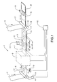
- Figure 1 is a schematic and simplified view of an arrangement 1 for manufacturing absorbent products, which is arranged in accordance with a preferred embodiment of the present invention. More specifically, the arrangement 1 is arranged for manufacturing absorbent products that start out as a first essentially continuous material web 2, which is fed forward in a known way from a roll (not shown) or the like, in a direction that is indicated by an arrow in Figure 1 .
- the first material web 2 consists of a backing layer for a disposable diaper, that is a material of the type that is non-permeable to liquid or that has at least a high resistance to the penetration of liquid, but which, however, is breathable.
- the first material web 2 consists suitably of a thin and waterproof plastic film of, for example, polyethylene, polypropylene or polyester.
- a laminate of non-woven material and plastic film or other suitable and previously-known layers of material can be utilized as a liquid-tight backing layer.
- the first material web 2 can be fed forward by means of two rollers 3, 4 which are arranged to give the first material web 2 that will become the backing layer, a certain given feed speed v 1 .
- Figure 1 also shows that the first material web 2 is processed in such a way that it comprises a printed motif 5.
- This motif 5 is suitably pre-printed on the first material web 2.
- the motif 5 is applied in a periodic way with a certain given interval, so that one and the same motif is provided on each individual product that is manufactured from the first material web 2.
- the motif 5 is indicated by broken lines in Figure 1 to indicate that it is printed on the underside of the first material web 2. In the finished product, the final position of the printed motif 5 will thus be in a predetermined position on the back of the product.
- the motif 5 is printed with certain given periodicity and is intended to be synchronized, which means that the final position of the motif 5 is intended to be in the same position on each individually manufactured product of the type in question.
- the first material web 2 is provided with a number of reference marks or synchronizing marks 6, suitably in the form of relatively short lines that are suitably pre-printed onto the first material web 2.
- the synchronizing marks 6 are printed on the underside of the first material web 2. The invention is not, however, restricted to this, it being possible to print the synchronizing marks 6 on both sides of the first material web 2.
- the synchronizing marks 6 are also indicated by broken lines, in order to indicate that they are printed on the underside of the first material web 2.
- the object of the respective synchronizing mark 6 is to constitute a detectable reference element, by means of which various work elements and process steps that are carried out by means of the arrangement 1 are synchronized correctly in relation to the respective printed motif 5.
- the motif 5 can be positioned in the correct position on the finished product.
- a processed element in the first material web 2 is utilized, in the form of a printed motif 5.
- the principle behind the invention is not limited to only the case when a printed motif is utilized.
- the invention can also be used for other positioned elements in the form of patterns, embossing, applications and ornamentation that constitute processing of the first material web 2.
- the principle behind the invention can be used for elements that consist of embossed patterns, folds, notches, holes and similar elements that are intended to be positioned in a predetermined, that is "synchronized", way on a finished product.
- the first material web 2 can be divided into a certain nominal division length L N , that is a length that is defined between two transverse positions 7, 8 that delimit a particular product.
- the nominal division length L N consists in particular of a product length that corresponds to the front edge and back edge of a finished product. These positions 7, 8 are indicated by broken lines in Figure 1 . However, these lines are not printed on the first material web 2.
- Each printed motif 5 is placed in a position that is in a given and predetermined relationship to the respective synchronizing mark 6. This means that the respective synchronizing mark 6 is printed a periodically recurring distance apart L S that corresponds to the periodicity of the printed motif 5.
- the first material web 2 is fed through a processing equipment 9 where a number of work elements and process steps are carried out in a way that is already known.
- work elements can comprise, for example, the application of various types of absorbent material, wadding material and the like, and any other material and components such as, for example, elastic, adhesive tape and the like.
- the work elements that are carried out in the processing equipment 9 can also comprise folding, cutting, ultrasound welding and other processing steps.
- manufacture of absorbent products by means of a series of such work elements is already known, and for this reason will not be described here in detail.
- the first material web 2 has passed a detecting device 10 just before it is fed into the processing equipment 9.
- the detecting device 10 is arranged to detect the position of each synchronizing mark 6.
- the feeding of the first material web 2 is carried out by means of a feeding device that preferably consists of a suction conveyor 11 which is a known feeding device that can be controlled to feed forward the first material web 2 at a given feed speed v 2 .
- the first material web 2 is fed past a gluing station 12 at which adhesive is applied in order to enable a subsequent outer layer to be glued on, in the way that will be described below.
- the detecting device 10 consists preferably of a suitable device for optical inspection, according to the embodiment in the form of a video camera that is arranged in association with the first material web 2.
- the detecting device 10 is arranged in such a way that it continually inspects and records images along the underside of the first material web 2 as shown schematically in Figure 2 .
- the detecting device 10 comprises a set of light-sensitive elements, by means of which it records the light transmission from the first material web 2 while this is moved in relation to the detecting device 10.
- the detecting device 10 is connected to a computer-based control unit 13. Information from the detecting device 10 is transmitted in this way to the control unit 13, which in turn is provided with software for image processing that is arranged to detect each synchronizing mark 6 that passes over the detecting device 10.
- the control unit 13 is connected, in a way that will be described in detail below, to a speed-regulating device 14 for controlling the speed v 1 at which the first material web 2 is fed forward.
- the control unit 13 is also connected to the suction conveyor 11 for regulating the speed v 2 of this.
- the detecting device 10 can be, for example, a CCD camera ("charged coupled device"), that is with a set of light-sensitive sensors arranged in one or more rows. By means of this arrangement, the position of each synchronizing mark 6 can be detected.
- the detecting device can be based on, for example, laser technology, that is with a laser light source that is utilized in conjunction with a light-sensitive detector to detect the position of the respective synchronizing mark 6.
- the synchronizing mark can consist of an electronically detectable sensor, for example of the transponder type, that is applied on the first material web 2 with the abovementioned periodicity L s .
- Such a synchronizing mark can then be read by a detecting device that comprises a radio transmitter and radio receiver for this purpose in a known way.
- said synchronizing marks can be printed with magnetic ink that can then be detected by a sensor that detects magnetism.
- the second material web 15 consists suitably of a non-woven material with a soft and smooth surface, such as, for example, a spun bond material of polypropylene fibre.
- Other examples of materials that are suitable for constituting the outer layer are perforated plastic films, such as, for example, a perforated polyester film.
- the second material web 15 is thus joined to the first material web 2 (together with any additional layers of material and other components that are added in association with the processing equipment 9 as described above) for example by means of the adhesive that was previously applied at the gluing station 12.
- a complete material web 16 is created, intended to define a number of manufactured products, which is fed forward in a direction that is indicated by an arrow in Figure 1 and taken up and fed forward by means of two additional driving units, for example in the form of two rotating feeding rollers 17, 18 arranged respectively over and under the complete material web 16. In this way, the complete material web 16 can be fed forward.
- a complete continuous material web 16 is thus created, consisting of a number of finished absorbent products that are still joined together.
- This material web 16 is finally fed past a cutting station 19, suitably of the "cross-cutter” type, where cutting Is carried out at positions that essentially correspond to the imaginary boundary lines 7, 8 for each finished product. In this way, a number of finished products are created in the form of absorbent products 20.
- this is arranged to detect the position of the respective synchronizing mark 6.
- Information regarding a detected position for a given synchronizing mark 6 is then used for various process steps that, for example, are carried out in the processing equipment 9 in order to ensure that the printed motif 5 is always positioned in a correct position on each finished product 20.
- FIG. 2 shows a view from above of a part of the first material web 2 that is fed forward in a direction that Is indicated by an arrow.
- the first material web 2 can be said to be divided into a number of products 20 that are delimited by means of imaginary lines 7, 8. In this way, a nominal division length L N is defined for each product 20. as described above.
- the material web 2 is also provided with a printed motif 5 Intended to be positioned in a predetermined way on the respective product 20.
- Figure 2 also shows how the detecting device 10 Is positioned at a time when the detection of the synchronizing mark 6 occurs, that is when the synchronizing mark 6 is just passing the detecting device 10.
- the detecting device 10 is suitably arranged with a detecting area that corresponds to a certain section in the form of a line or zone 24 in the machine direction and that goes from the edge of the material web 2 inwards towards its centre.
- the synchronizing mark 6 is preferably positioned with its full extent within this zone 24. The boundary of this zone 24 is indicated in Figure 2 by a dash dotted line.
- the x-axis represents a colour scale between red (positive values along the x-axis) and green (negative values along the x-axis).
- An additional axis that also passes through the origin of the coordinate system represents a colour scale between yellow (positive values) and blue (negative values).
- the method is called in general the CIELab method and can be used to distinguish between all possible tints by the selection of coordinates according to the above principles. The method is also suitable for use with the present invention.
- the formula above is comprised in an international standard for colour detection, ISO 5631. The theory according to this standard can thus be utilized with the Invention in such a way that the relevant synchronizing mark 6 can be given a colour with a predefined value of ⁇ E ab * as above.
- a synchronizing mark 6 that, for example, consists of a red line (with a certain predetermined value of ⁇ E ab *) can thus be detected by a detecting device 10 arranged to detect red objects.
- the detecting device 10 detects a tint in its detecting area with a certain predetermined deviation from said predetermined value, this is interpreted as there being no synchronizing marks present at the detection.
- the invention is used to detect a synchronizing mark 6 by distinguishing its colour or colour combination from colours or colour combinations elsewhere along the section 24 where detection can be carried out.
- the synchronizing mark 6 is printed In a colour or colour composition that is different from any section of the printed motif that can be found along the zone 24.
- Figure 3 shows an embodiment with a printed motif 5' that Is modified slightly in relation to what is shown in Figure 2 .
- Components In Figure 3 that are the same as corresponding components in Figure 2 are given the same reference numeral. More specifically, Figure 3 shows a printed motif 5' in the form of a stick man with a leg 25 that extend into the zone 24, that is within the area that is read by the detecting device 10.
- the detecting device 10 will be able to distinguish between the synchronizing mark 6 and the leg 25.
- the invention thus enables the printed motif 5' to utilize in principle the whole width of the first material web 2.
- the synchronizing mark 6 can still be distinguished and detected by the detecting device 10, even at relatively high process speeds.
- a precondition is that the parts of the printed motif 5' that are found in the zone 24 do not have a colour or other optical characteristics that are the same as corresponding characteristics that the detecting device 10 is arranged to detect.
- the synchronizing mark 6 is designed in a way and with optical characteristics, suitably concerning its colour or colour combination, that differs from the design of any parts of a printed motif that is found in the zone 24.
- the invention is not limited to the type of distinguishing that is based only on colour.
- the invention can be realized by detection that is based on other optical characteristics, such as, for example, shape and contrast.
- the synchronizing mark can be designed with a level of contrast that differs essentially from the level of contrast that is to be found in any section of the printed motif that is to be found in the zone 24.
- an alternative synchronizing mark can consist of two or more consecutive lines, instead of only one line as shown in Figure 3 .
- these can be printed in two separate colours, for example red and green.
- the detecting device and the control unit that are used can then be arranged so that a synchronizing mark is detected if and only if there is a detection of a red line followed by a green line.
- a detecting device is suitably used with two separate detectors, one for each colour (red and green respectively).
- the parts of the motif that come within the zone 24 can easily be partly red and green.
- the precondition for this embodiment is, however, that any red and green sections in the motif are not positioned in such a way that they could be perceived by the detecting device as a red line that is followed by a green line.
- a synchronizing mark is thus used that in turn can be said to comprise two or more elements which are arranged as a predetermined combination of optical characteristics. This combination can then be detected by the detecting device. As a result of the colour combination in question not being found elsewhere in the zone 24, the synchronizing mark 6 can be detected in a reliable way.
- a line 26 that comprises a "pulse"-like section 27.
- This section 27 corresponds to a particular time slot, that is a period of time when it is possible to carry out detection with the detecting device 10. During the remaining parts of the division length L N , no such detection is possible.
- the time slot corresponds to a short period of time t that occurs when the synchronizing mark 6 is expected to pass the detecting device 10.
- the synchronizing mark 6 has preferably a length (that is in the longitudinal direction of the material web 2) that is of the order of 15 mm or more.
- the width of the synchronizing mark 6 (that is in the transverse direction of the material web 2) is preferably of the order of 25 mm.
- An object of the arrangement according to Figure 1 is to synchronize the first material web 2 with its printed motif 5 in a correct way, so that the printed motif 5 is always positioned in a correct position on each finished product 20.
- the control unit 13 is preferably arranged with a virtual, data-based reference function or "master" function, which will now be described with reference initially to Figure 4a .
- the virtual master function is a cyclic clock that preferably turns one revolution per product 20. As is described in detail below, the master function is not limited just to this periodicity. An event-controlled reading off of this clock can be interpreted as the relative position of the event in question in relation to a fixed point on the product in question, that is in relation to a type of virtual zero point or reference for the product.
- Figure 4a shows the virtual master function in the form of a ramp-like curve 21 that recurs at regular intervals.
- the detecting device 10 is utilized first to detect a particular synchronizing mark 6 along the first material web 2, according to the principles that were described above.
- the control unit 13 is utilized to detect in what position along the virtual master function 21 the synchronizing mark 6 is located. Information about the actual position of the virtual master function 21 is thus recorded by means of the control unit 13.
- the control unit 13 compares the actual position of the virtual master function (actual value) with an expected position (desired value).
- the speed v 1 of the first material web 2 is then changed in relation to the speed v 2 of the suction conveyor 11 in response to any deviation between the actual position and expected position (that is the desired value).
- the lower the speed v 1 in comparison with v 2 the more the material of the first material web 2 will be stretched. This is then utilized to obtain a correct synchronization of the first material web 2.
- Figure 4a shows said reference function in the form of a ramp-like curve 21 that recurs at regular intervals that symbolizes a periodic clock that is utilized for detecting the respective synchronizing mark 6.
- the curve 21 is drawn in an xy-coordinate system where the x-axis corresponds to the time t, and where a period in the curve 21 corresponds to the time T that it takes for a nominal division length L N of the material in question to pass the detecting device 10.
- the y-axis corresponds to a length L for the first material web 2, with a maximal value L N of the curve 21 corresponding to the length of the respective product.
- the curve 21 indicates in a schematic way a rise from a zero value that indicates one end of a product to a maximal value L N that indicates the other end of the product and that, according to the described embodiment, corresponds to the length of the product.
- a value of the position of the virtual master function that has been read off (when a synchronizing mark 6 has just been detected) is thus compared periodically with an expected position along the virtual master function.
- the expected value that is the desired value
- the precise position for this desired value 22 is determined by a number of factors, such as, for example, the equipment comprised in the arrangement 1, the dimensions of the comprised material, the process speed, etc.
- the curve 21 with its desired value 22 thus consists of predefined data that is stored in the control unit 13. For this reason, the reference function or master function that is illustrated by the curve 21 can be said to be "virtual", as it is thus generated and stored in the form of software in the control unit 13.
- Figure 4b shows an alternative embodiment, in which the virtual master function 21 is arranged in such a way that two periods in the curve 21 correspond to the time T that it takes for a nominal division length L N of the material in question to pass the detecting device 10.
- Figure 4c shows yet another embodiment of the invention in which the virtual master function 21 is arranged in such a way that a period in the curve 21 corresponds to twice the time T that it takes for a nominal division length L N of the material in question to pass the detecting device 10.
- the invention can be realized in such a way that the master function 21 consists of a cyclic clock where the number of cycles T per product 20, or alternatively the number of products 20 per cycle T, consists of a whole number.
- the principle is used that detection of a given synchronizing mark 6 is carried out using the detecting device 10. This results in the recording of a position along the curve 21 that corresponds to this detected synchronizing mark 6. This position then constitutes an actual value that is indicated schematically by the reference numeral 23 in Figures 4a, 4b, 4c .
- the actual value 23 will consist of a numerical value corresponding to a certain proportion of the total product length.
- control unit 13 is arranged to compare the desired value 22 and the actual value 23 (that is the actual position) that was recorded during the detection of a particular synchronizing mark 6.
- the desired value 22 and the actual value 23 there is a difference between the desired value 22 and the actual value 23.
- This difference can be expressed as a difference between the proportion of the whole product length that corresponds to the desired value 22 minus the proportion of the product length that corresponds to the actual value 23. If there is a relatively large difference between the desired value 22 and the actual value 23 (as shown in, for example, Figure 4a ), the printed motif 5 would be positioned on the first material web 2 displaced somewhat in relation to its intended position, that is the motif 5 would not then be correctly synchronized.
- the arrangement is arranged in such way that the position of the printed motif 5 on the finished product 20 is adjusted by stretching the first material web 2 if there is such a deviation between the desired value 22 and the measured value 23.
- the synchronizing marks 6 are pre-printed on the first material web 2 in such a way that its periodicity L S is somewhat shorter than the intended product length L N . This means that the distance L S between two consecutive synchronizing marks 6 is shorter than the product length L N , which in turn corresponds to the intended final length of the finished product 20.
- the distance L S between two synchronizing marks 6 is shorter than the product length L N makes it possible to stretch the first material web 2 to a certain extent, in order in this way to position the printed motif 5 so that, in its final position, it is in the correct position on the finished product 20.
- the abovementioned stretching of the first material web 2 is achieved by a regulation of the speed of the first speed-regulating device 14, which in turn controls the feed speed v 1 for the first material web 2. More specifically, the control unit 13 is arranged to control the speed-regulating device 14 in such a way that the first material web 2 is given a speed v 1 that is somewhat lower than the speed v 2 of the suction conveyor 11. This leads in turn to a stretching of the material in the first material web 2 when it runs through the processing equipment 9.
- the position of the printed motif 5 on the finished product and thereby also the position of the respective synchronizing mark 6, is adjusted in such a way that the deviation between the desired value 22 and the actual value 23 relating to the position of the synchronizing mark 6 is eliminated.
- the distance L S between two consecutive synchronizing marks 6 is of the order of 2% shorter than the product length L N .
- the ratio between the product length L N and the distance between two synchronizing marks L S can, however, vary depending upon the comprised material and which type of processing equipment is utilized. Nor is the invention limited to the nominal division length having to be connected to the product length, but instead other divisions of first material web 2 are also possible.
- the arrangement that is described is used for the detection of synchronizing marks 6, the position of which is detected and utilized for synchronizing a printed motif 5 in the correct intended position on a finished product.
- the detection of the respective synchronizing mark 6 is carried out as described above, by utilizing a colour or colour composition that is distinct from any sections of a printed motif that may be found along the zone 24 (see Figure 3 ).
- the actual synchronization is carried out using a virtual reference function or "master" function that is stored in the control unit 13 and that is arranged to provide references in order to make it possible to stretch the first material web 2 if a deviation is recorded between an actual position and the expected position of the respective synchronizing mark 6. In this way, a simple and accurate process is obtained for synchronizing the printed motif 5.
- the invention is not limited to what is described above, various embodiments being possible within the framework of the patent claims.
- the invention is particularly suitable for use in association with a manufacturing process for making absorbent products such as diapers, incontinence protectors, sanitary towels and panty liners, but, however, is not limited only to this type of product, being able, in principle, to be utilized in other manufacturing processes that are based on an essentially continuous material web being divided into a certain product length and where a printed motif or other similar process is synchronized in the correct position.
- the respective synchronizing mark can be positioned in a position that is intended to be cut away from the product after the synchronizing mark has been detected.
- the respective synchronizing mark can be arranged so that it is concealed by, for example, the tapes that are applied after the detection has been carried out.
- the invention is particularly suitable for use with the applications where the first material web 2 consists of a material intended to form a backing layer in a diaper. Such a material then consists suitably of a plastic film that is non-permeable to liquid, which is suitable for the abovementioned stretching procedure and is also suitable for printing with high quality colour motifs.
- the invention can, however, be used with other material than just the backing layer for diapers, for example other elastic and stretchable material webs, for example non-woven material, that is fibrous materials with fibres such as for example polyolefins, that is polymer material such as polyethylene and polypropylene, or alternatively polyester, nylon or the like.
- the invention can also be utilized when the first material web consists of some other type of synthetic or textile material.
- the invention can also be used for different types of laminated product comprising varying numbers of layers of material.
- this can be provided by being pre-printed onto the first material web 2.
- the actual manufacturing process that is obtained with the processing equipment 9 can comprise a process for printing the motif.
- a period length T in the reference function 21 can correspond to a product length, as described above.
- a period length T can correspond to two or more product lengths, or a certain proportion of a product length. This means that the synchronizing marks can be positioned in a corresponding way, for example in every other position in comparison with what is shown in Figure 1 .
- the invention is not limited to a virtual master function where a period corresponds clearly to a product length.
- the invention can be arranged in such a way that a given product length corresponds to two or more synchronizing marks and thus also two or more periods in the virtual master function.
Landscapes
- Health & Medical Sciences (AREA)
- Engineering & Computer Science (AREA)
- Animal Behavior & Ethology (AREA)
- General Health & Medical Sciences (AREA)
- Biomedical Technology (AREA)
- Heart & Thoracic Surgery (AREA)
- Vascular Medicine (AREA)
- Life Sciences & Earth Sciences (AREA)
- Manufacturing & Machinery (AREA)
- Epidemiology (AREA)
- Public Health (AREA)
- Veterinary Medicine (AREA)
- Mechanical Engineering (AREA)
- Controlling Rewinding, Feeding, Winding, Or Abnormalities Of Webs (AREA)
- Treatment Of Fiber Materials (AREA)
- Absorbent Articles And Supports Therefor (AREA)
Claims (11)
- Procédé de détection d'une marque de synchronisation (6) étant utilisée dans le positionnement synchronisé d'au moins une bande de matériau essentiellement continue (2), pour la fabrication de produits (20) qui comprennent un motif imprimé (5; 5') ou d'autres éléments positionnés dans la forme d'images, de gaufrage, d'applications et d'ornementation, ladite bande de matériau (2) étant destinée à être divisée en une longueur de division nominale (LN), la longueur de division nominale (LN) étant définie entre deux positions transversales (7, 8) qui délimitent un produit particulier, ladite bande matériau (2) comprenant des marques de synchronisation (6) avec une périodicité (LS), ledit procédé comprenant:l'établissement d'une zone de détection longitudinale (24) le long d'une arête latérale de la bande de matériau, ladite zone de détection longitudinale (24) comprenant une partie du motif imprimé (5;5') et la marque de synchronisation (6);la détection de la marque de synchronisation respective (6) pour le positionnement du motif respectif (5; 5') dans une position prédéterminée sur le produit respectif (20), ladite détection étant effectuée dans ladite zone de détection longitudinale (24) dans une direction de machine de ladite bande de matériau (2);caractérisé en ce que ledit procédé comprend:la détection de ladite marque de synchronisation (6) en distinguant ses caractéristiques optiques de caractéristiques optiques du motif imprimé (5;5') dans le reste de ladite section (24).
- Procédé selon la revendication 1, caractérisé en ce qu'il comprend la détection de ladite marque de synchronisation (6) en distinguant sa couleur de couleurs dans le motif imprimé (5; 5').
- Procédé selon la revendication 1, caractérisé en ce qu'il comprend la détection de ladite marque de synchronisation (6) en distinguant sa combinaison de couleurs de couleurs et de combinaisons de couleurs dans le motif imprimé (5; 5').
- Procédé selon la revendication 1, caractérisé en ce que ladite détection comprend la distinction des caractéristiques optiques dans la forme de la forme, du contraste ou des caractéristiques similaires de la marque de synchronisation (6).
- Procédé selon l'une quelconque des revendications précédentes, caractérisé en ce que ladite détection est effectuée au moyen d'un dispositif de détection (10) agencé pour détecter une couleur ou une composition de couleurs prédéterminée.
- Procédé selon l'une quelconque des revendications précédentes, caractérisé en ce que ladite marque de synchronisation (6) comprend deux ou plusieurs éléments qui sont disposés comme une combinaison prédéterminée, agencée pour être détectée par ledit dispositif de détection (10).
- Procédé selon l'une quelconque des revendications précédentes, caractérisé en ce que la longueur de division nominale (LN) est constituée d'une longueur de produit prédéterminée (LP) pour ledit produit (20).
- Procédé selon l'une quelconque des revendications précédentes, caractérisé en ce que ledit produit (20) est constitué d'un produit absorbant et en ce que le procédé comprend la fourniture d'une bande de matériau (2) dans la forme d'une couche d'un tel produit absorbant.
- Procédé selon la revendication 10, caractérisé en ce que la bande de matériau (2) se compose d'une couche de support pour ledit produit (20).
- Dispositif de détection d'une marque de synchronisation (6) qui est utilisé pour le positionnement synchronisé d'au moins une bande de matériau continue (2) pour la fabrication de produits (20) qui comprennent un motif imprimé (5; 5') ou d'autres éléments positionnés dans la forme d'images, de gaufrage, d'applications et d'ornementation, ladite bande de matériau (2) étant destinée à être divisée en une longueur de division nominale (LN), la longueur de division nominale (LN) étant définie entre deux positions transversales (7, 8) qui délimitent un produit particulier, ladite bande matériau (2) comprenant des marques de synchronisation (6) avec une périodicité (LS), ledit dispositif comprenant un détecteur (10) pour la détection de la marque de synchronisation respective (6) dans une direction de machine de ladite bande de matériau (2), et une unité de commande à base d'ordinateur (13) disposée pour ladite synchronisation, une partie du motif respectif (5; 5') étant positionnée dans une zone de détection longitudinale (24) le long d'une arête longitudinale de la bande de matériau, ladite zone de détection longitudinale comprenant une partie du motif imprimé et de la marque de synchronisation, caractérisé en ce que ladite unité de commande (13) est agencée pour la détection de ladite marque de synchronisation (6) en distinguant ses caractéristiques optiques de caractéristiques optiques du motif imprimé.
- Article absorbant (20), tel qu'une couche-culotte, une protection contre l'incontinence, une serviette hygiénique ou un protège-slip, d'une longueur de division prédéterminée (LN), la longueur de division nominale (LN) étant définie entre deux positions transversales (7, 8) qui délimitent un produit particulier, ledit article absorbant (2) comprenant un matériau de support (2) qui comprend un élément traité dans la forme d'un motif imprimé (5) ou d'autres éléments positionnés dans la forme d'images, de gaufrage, d'applications et d'ornementation, et comprenant une marque de synchronisation (6) avec une périodicité prédéterminée (LS), avec ladite marque de synchronisation (6) et une partie dudit motif imprimé (5) étant arrangées dans une zone de détection longitudinale (24) le long d'une arête latérale dudit matériau de support (2), caractérisé en ce que ladite marque de synchronisation (6) est pourvue de caractéristiques optiques qui peuvent être distinguées de caractéristiques optiques du motif imprimé (5).
Priority Applications (1)
| Application Number | Priority Date | Filing Date | Title |
|---|---|---|---|
| PL06733373T PL2010118T3 (pl) | 2006-04-27 | 2006-04-27 | Sposób i układ do wykrywania znaku synchronizującego wykorzystywanego w synchronicznym pozycjonowaniu co najmniej jednego, zasadniczo ciągłego pasa materiału |
Applications Claiming Priority (1)
| Application Number | Priority Date | Filing Date | Title |
|---|---|---|---|
| PCT/SE2006/000518 WO2007126347A1 (fr) | 2006-04-27 | 2006-04-27 | Procédé et dispositif permettant la détection d'une marque de synchronisation utilisée dans le positionnement synchronisé d'au moins une nappe de matière sensiblement continue |
Publications (3)
| Publication Number | Publication Date |
|---|---|
| EP2010118A1 EP2010118A1 (fr) | 2009-01-07 |
| EP2010118A4 EP2010118A4 (fr) | 2011-06-29 |
| EP2010118B1 true EP2010118B1 (fr) | 2013-08-21 |
Family
ID=38655786
Family Applications (1)
| Application Number | Title | Priority Date | Filing Date |
|---|---|---|---|
| EP06733373.2A Revoked EP2010118B1 (fr) | 2006-04-27 | 2006-04-27 | Procédé et dispositif permettant la détection d'une marque de synchronisation utilisée dans le positionnement synchronisé d'au moins une nappe de matière sensiblement continue |
Country Status (12)
| Country | Link |
|---|---|
| US (1) | US8157776B2 (fr) |
| EP (1) | EP2010118B1 (fr) |
| JP (1) | JP2009535280A (fr) |
| CN (1) | CN101400328B (fr) |
| AU (1) | AU2006342829B8 (fr) |
| BR (1) | BRPI0621626B8 (fr) |
| ES (1) | ES2428871T3 (fr) |
| MX (1) | MX2008011114A (fr) |
| MY (1) | MY141352A (fr) |
| PL (1) | PL2010118T3 (fr) |
| TN (1) | TNSN08364A1 (fr) |
| WO (1) | WO2007126347A1 (fr) |
Families Citing this family (55)
| Publication number | Priority date | Publication date | Assignee | Title |
|---|---|---|---|---|
| US8417374B2 (en) | 2004-04-19 | 2013-04-09 | Curt G. Joa, Inc. | Method and apparatus for changing speed or direction of an article |
| US7638014B2 (en) | 2004-05-21 | 2009-12-29 | Curt G. Joa, Inc. | Method of producing a pants-type diaper |
| US9622918B2 (en) | 2006-05-18 | 2017-04-18 | Curt G. Joe, Inc. | Methods and apparatus for application of nested zero waste ear to traveling web |
| US9433538B2 (en) | 2006-05-18 | 2016-09-06 | Curt G. Joa, Inc. | Methods and apparatus for application of nested zero waste ear to traveling web and formation of articles using a dual cut slip unit |
| US10456302B2 (en) | 2006-05-18 | 2019-10-29 | Curt G. Joa, Inc. | Methods and apparatus for application of nested zero waste ear to traveling web |
| US9550306B2 (en) | 2007-02-21 | 2017-01-24 | Curt G. Joa, Inc. | Single transfer insert placement and apparatus with cross-direction insert placement control |
| US9944487B2 (en) | 2007-02-21 | 2018-04-17 | Curt G. Joa, Inc. | Single transfer insert placement method and apparatus |
| ES2922456T3 (es) | 2007-02-21 | 2022-09-15 | Joa Curt G Inc | Método y aparato de colocación de insertos de transferencia simple |
| US8398793B2 (en) | 2007-07-20 | 2013-03-19 | Curt G. Joa, Inc. | Apparatus and method for minimizing waste and improving quality and production in web processing operations |
| US9387131B2 (en) * | 2007-07-20 | 2016-07-12 | Curt G. Joa, Inc. | Apparatus and method for minimizing waste and improving quality and production in web processing operations by automated threading and re-threading of web materials |
| US8182624B2 (en) | 2008-03-12 | 2012-05-22 | Curt G. Joa, Inc. | Registered stretch laminate and methods for forming a registered stretch laminate |
| JP5264562B2 (ja) * | 2009-03-02 | 2013-08-14 | ユニ・チャーム株式会社 | 吸収性物品の製造装置及び製造方法 |
| IT1393147B1 (it) * | 2009-03-09 | 2012-04-11 | Sacmi Labelling S P A Ora Sacmi Verona S P A | Apparato e metodo di alimentazione |
| US8145344B2 (en) | 2009-06-02 | 2012-03-27 | The Procter & Gamble Company | Systems and methods for controlling phasing of advancing substrates in absorbent article converting lines |
| US8145338B2 (en) | 2009-06-02 | 2012-03-27 | The Procter & Gamble Company | Systems and methods for detecting and rejecting defective absorbent articles from a converting line |
| US8145343B2 (en) | 2009-06-02 | 2012-03-27 | The Procter & Gamble Company | Systems and methods for controlling registration of advancing substrates in absorbent article converting lines |
| US9089453B2 (en) | 2009-12-30 | 2015-07-28 | Curt G. Joa, Inc. | Method for producing absorbent article with stretch film side panel and application of intermittent discrete components of an absorbent article |
| US8460495B2 (en) | 2009-12-30 | 2013-06-11 | Curt G. Joa, Inc. | Method for producing absorbent article with stretch film side panel and application of intermittent discrete components of an absorbent article |
| EP2357138B1 (fr) * | 2010-02-12 | 2012-10-17 | Tetra Laval Holdings & Finance S.A. | Dispositif et procédé pour alimenter une bande de matériau d'emballage |
| DE102010011388A1 (de) * | 2010-03-12 | 2011-09-15 | Krones Ag | Vorrichtung zum Bearbeiten von Etikettenstreifen mit Positionserfassung |
| US8663411B2 (en) | 2010-06-07 | 2014-03-04 | Curt G. Joa, Inc. | Apparatus and method for forming a pant-type diaper with refastenable side seams |
| US9603752B2 (en) | 2010-08-05 | 2017-03-28 | Curt G. Joa, Inc. | Apparatus and method for minimizing waste and improving quality and production in web processing operations by automatic cuff defect correction |
| US9566193B2 (en) | 2011-02-25 | 2017-02-14 | Curt G. Joa, Inc. | Methods and apparatus for forming disposable products at high speeds with small machine footprint |
| US8656817B2 (en) | 2011-03-09 | 2014-02-25 | Curt G. Joa | Multi-profile die cutting assembly |
| USD684613S1 (en) | 2011-04-14 | 2013-06-18 | Curt G. Joa, Inc. | Sliding guard structure |
| US8820380B2 (en) | 2011-07-21 | 2014-09-02 | Curt G. Joa, Inc. | Differential speed shafted machines and uses therefor, including discontinuous and continuous side by side bonding |
| JP5820737B2 (ja) * | 2012-02-13 | 2015-11-24 | 日産自動車株式会社 | 帯状ワークの搬送装置および搬送方法 |
| CA2807809C (fr) | 2012-02-20 | 2019-07-23 | Curt G. Joa, Inc. | Methode de formation de liaisons entre des composants discrets d'articles jetables |
| US9908739B2 (en) | 2012-04-24 | 2018-03-06 | Curt G. Joa, Inc. | Apparatus and method for applying parallel flared elastics to disposable products and disposable products containing parallel flared elastics |
| US9283683B2 (en) | 2013-07-24 | 2016-03-15 | Curt G. Joa, Inc. | Ventilated vacuum commutation structures |
| USD703711S1 (en) | 2013-08-23 | 2014-04-29 | Curt G. Joa, Inc. | Ventilated vacuum communication structure |
| USD703247S1 (en) | 2013-08-23 | 2014-04-22 | Curt G. Joa, Inc. | Ventilated vacuum commutation structure |
| USD703712S1 (en) | 2013-08-23 | 2014-04-29 | Curt G. Joa, Inc. | Ventilated vacuum commutation structure |
| USD703248S1 (en) | 2013-08-23 | 2014-04-22 | Curt G. Joa, Inc. | Ventilated vacuum commutation structure |
| USD704237S1 (en) | 2013-08-23 | 2014-05-06 | Curt G. Joa, Inc. | Ventilated vacuum commutation structure |
| US9289329B1 (en) | 2013-12-05 | 2016-03-22 | Curt G. Joa, Inc. | Method for producing pant type diapers |
| JP5953296B2 (ja) * | 2013-12-13 | 2016-07-20 | 花王株式会社 | 吸収体の製造装置 |
| BR112016028062B1 (pt) | 2014-06-13 | 2021-12-14 | Essity Hygiene And Health Aktiebolag | Unidade de empacotamento para artigos de higiene e método de formação de uma unidade de empacotamento para artigos de higiene |
| US10086989B2 (en) | 2014-06-13 | 2018-10-02 | Sca Hygiene Products Ab | Packaging unit for hygiene articles and a method of forming a packaging unit |
| AU2014396902B2 (en) * | 2014-06-13 | 2017-01-19 | Essity Hygiene And Health Aktiebolag | A packaging unit for hygiene articles and a method of forming a packaging unit |
| RU2644113C1 (ru) | 2014-06-13 | 2018-02-07 | Ска Хайджин Продактс Аб | Способ образования обертывающего листа, имеющего улучшенную герметизирующую способность |
| US9834355B2 (en) | 2014-06-13 | 2017-12-05 | Sca Hygiene Products Ab | Packaging unit having improved sealing, and a method for forming such a packaging unit |
| CN106456418A (zh) | 2014-06-13 | 2017-02-22 | Sca卫生用品公司 | 具有改良密封性和使用者提示装置的包装单元及用于制造此包装单元的方法 |
| JP6534838B2 (ja) * | 2015-03-19 | 2019-06-26 | 株式会社イシダ | 製袋包装機 |
| CA2991328C (fr) | 2015-07-24 | 2021-10-26 | Curt G. Joa, Inc. | Appareil et procedes de commutation a vide |
| US20170128274A1 (en) * | 2015-11-11 | 2017-05-11 | The Procter & Gamble Company | Methods and Apparatuses for Registering Substrates in Absorbent Article Converting Lines |
| WO2019232219A1 (fr) | 2018-05-31 | 2019-12-05 | Kimberly-Clark Wordlwide, Inc. | Procédé de fabrication de produits personnalisés |
| KR102683581B1 (ko) * | 2018-05-31 | 2024-07-12 | 킴벌리-클라크 월드와이드, 인크. | 맞춤형 제품 제조 방법 |
| BE1027094B1 (de) * | 2019-03-05 | 2020-10-05 | Phoenix Contact Gmbh & Co | Beschriftungsprofil zur Kennzeichnung von Elektroinstallationen und Verfahren zum Herstellen von Beschriftungsstreifen |
| CN113454850B (zh) * | 2019-03-05 | 2023-11-14 | 凤凰接触股份有限及两合公司 | 用于标示电气装置的标记型材和制造标记条的方法 |
| CN110179590A (zh) * | 2019-04-16 | 2019-08-30 | 广东中科鑫雁科技有限公司 | 一种卫生用品芯体材料吸水高分子的施加机构及方法 |
| US11737930B2 (en) | 2020-02-27 | 2023-08-29 | Curt G. Joa, Inc. | Configurable single transfer insert placement method and apparatus |
| CN112587309B (zh) * | 2020-12-10 | 2022-02-11 | 福建恒安集团有限公司 | 一种增加导流及合身的芯体制造方法 |
| CN114469526B (zh) * | 2022-01-29 | 2023-06-09 | 深达创芯(深圳)科技有限公司 | 吸收制品及其制备方法、用于制备吸收制品的生产系统 |
| DE102022207518B4 (de) * | 2022-07-22 | 2024-07-18 | OPTIMA life science GmbH | Verfahren und Vorrichtung zur positionsgenauen Bearbeitung einer Materialbahn |
Family Cites Families (14)
| Publication number | Priority date | Publication date | Assignee | Title |
|---|---|---|---|---|
| US3556509A (en) * | 1968-08-21 | 1971-01-19 | Harris Intertype Corp | Printed web ribbon registration control system |
| SE323118B (fr) * | 1968-08-21 | 1970-04-27 | Svenska Ackumulator Ab | |
| US4837715A (en) * | 1987-01-27 | 1989-06-06 | Kimberly-Clark Corporation | Method and apparatus for detecting the placement of components on absorbent articles |
| US5235515A (en) | 1992-02-07 | 1993-08-10 | Kimberly-Clark Corporation | Method and apparatus for controlling the cutting and placement of components on a moving substrate |
| US5766389A (en) | 1995-12-29 | 1998-06-16 | Kimberly-Clark Worldwide, Inc. | Disposable absorbent article having a registered graphic and process for making |
| FR2755900B1 (fr) * | 1996-11-15 | 1999-01-29 | Toxot Sciences & Applic | Presse multicouleur a la continue par jet d'encre, procede de synchronisation d'une telle presse, et produit imprime obtenu a l'aide d'une telle presse |
| US6955733B2 (en) | 1997-12-19 | 2005-10-18 | The Procter & Gamble Company | Method and system for registering pre-produced webs with variable pitch length |
| US6444064B1 (en) | 1997-12-19 | 2002-09-03 | Procter & Gamble Company | Registration system for phasing simultaneously advancing webs of material having variable pitch lengths |
| AU5803898A (en) | 1997-12-19 | 1999-07-12 | Procter & Gamble Company, The | Registration system for phasing simultaneously advancing webs of material havingvariable pitch lengths |
| US6354984B1 (en) | 1999-04-02 | 2002-03-12 | Kimberly-Clark Worldwide, Inc. | Indirect registration of elements of web-derived product |
| JP3351763B2 (ja) * | 1999-07-19 | 2002-12-03 | 花王株式会社 | 吸収性物品の製造方法 |
| US20030105443A1 (en) * | 2000-07-10 | 2003-06-05 | The Procter & Gamble Company | Absorbent article comprising mircroporous film with registration mark |
| JP4246020B2 (ja) * | 2003-09-08 | 2009-04-02 | 王子製紙株式会社 | 吸収性物品の製造方法 |
| US6957160B2 (en) | 2003-12-09 | 2005-10-18 | The Procter & Gamble Company | Method and system for registering pre-produced webs with variable pitch length |
-
2006
- 2006-04-27 AU AU2006342829A patent/AU2006342829B8/en not_active Ceased
- 2006-04-27 BR BRPI0621626A patent/BRPI0621626B8/pt not_active IP Right Cessation
- 2006-04-27 EP EP06733373.2A patent/EP2010118B1/fr not_active Revoked
- 2006-04-27 MX MX2008011114A patent/MX2008011114A/es active IP Right Grant
- 2006-04-27 WO PCT/SE2006/000518 patent/WO2007126347A1/fr not_active Ceased
- 2006-04-27 US US12/297,704 patent/US8157776B2/en active Active
- 2006-04-27 PL PL06733373T patent/PL2010118T3/pl unknown
- 2006-04-27 CN CN2006800538107A patent/CN101400328B/zh not_active Expired - Lifetime
- 2006-04-27 JP JP2009507620A patent/JP2009535280A/ja active Pending
- 2006-04-27 ES ES06733373T patent/ES2428871T3/es not_active Expired - Lifetime
-
2007
- 2007-04-13 MY MYPI20070582A patent/MY141352A/en unknown
-
2008
- 2008-09-19 TN TNP2008000364A patent/TNSN08364A1/en unknown
Also Published As
| Publication number | Publication date |
|---|---|
| AU2006342829A8 (en) | 2012-12-13 |
| EP2010118A1 (fr) | 2009-01-07 |
| BRPI0621626B1 (pt) | 2018-02-06 |
| US20090082747A1 (en) | 2009-03-26 |
| MY141352A (en) | 2010-04-16 |
| AU2006342829B8 (en) | 2012-12-13 |
| AU2006342829B2 (en) | 2012-11-22 |
| WO2007126347A1 (fr) | 2007-11-08 |
| JP2009535280A (ja) | 2009-10-01 |
| US8157776B2 (en) | 2012-04-17 |
| ES2428871T3 (es) | 2013-11-12 |
| MX2008011114A (es) | 2008-09-08 |
| PL2010118T3 (pl) | 2013-12-31 |
| CN101400328A (zh) | 2009-04-01 |
| TNSN08364A1 (en) | 2009-12-29 |
| AU2006342829A1 (en) | 2007-11-08 |
| EP2010118A4 (fr) | 2011-06-29 |
| CN101400328B (zh) | 2012-05-09 |
| BRPI0621626A2 (pt) | 2011-12-13 |
| BRPI0621626B8 (pt) | 2021-06-22 |
Similar Documents
| Publication | Publication Date | Title |
|---|---|---|
| EP2010118B1 (fr) | Procédé et dispositif permettant la détection d'une marque de synchronisation utilisée dans le positionnement synchronisé d'au moins une nappe de matière sensiblement continue | |
| EP2010443B1 (fr) | Procédé et dispositif permettant le positionnement synchronisé d'au moins une bande de matière sensiblement continue | |
| EP1667843B1 (fr) | Systeme et procede pour incorporer des elements graphiques dans des articles absorbants | |
| US6092002A (en) | Variable tension process and apparatus for continuously moving layers | |
| EP2079421B1 (fr) | Article imprimé en trois dimensions | |
| EP0938441B1 (fr) | Procede et dispositif de controle de calage de materiau imprime en continu | |
| EP1773594B1 (fr) | Procede de correction de la variabilite de developpement dans des materiaux extensibles imprimes | |
| WO2000045767A1 (fr) | Procedes et dispositifs pour la fabrication d'articles absorbants jetables | |
| US6986820B2 (en) | Processes and apparatus for making disposable absorbent articles | |
| RU2401654C2 (ru) | Способ и устройство для обнаружения синхронизирующей метки, используемой при синхронизированном позиционировании, по меньшей мере, одного, по существу, непрерывного полотна материала | |
| RU2421390C2 (ru) | Способ и устройство для синхронизированного позиционирования, по меньшей мере, одного, по существу, непрерывного полотна материала | |
| MXPA99004222A (en) | Variable tension process and apparatus for continuously moving layers | |
| MXPA00006243A (en) | Registration system for phasing simultaneously advancing webs of material having variable pitch lengths | |
| HK1022133B (en) | Process and apparatus for registration control of material printed at machine product length |
Legal Events
| Date | Code | Title | Description |
|---|---|---|---|
| PUAI | Public reference made under article 153(3) epc to a published international application that has entered the european phase |
Free format text: ORIGINAL CODE: 0009012 |
|
| 17P | Request for examination filed |
Effective date: 20081111 |
|
| AK | Designated contracting states |
Kind code of ref document: A1 Designated state(s): AT BE BG CH CY CZ DE DK EE ES FI FR GB GR HU IE IS IT LI LT LU LV MC NL PL PT RO SE SI SK TR |
|
| AX | Request for extension of the european patent |
Extension state: AL BA HR MK YU |
|
| A4 | Supplementary search report drawn up and despatched |
Effective date: 20110526 |
|
| 17Q | First examination report despatched |
Effective date: 20120202 |
|
| DAX | Request for extension of the european patent (deleted) | ||
| GRAP | Despatch of communication of intention to grant a patent |
Free format text: ORIGINAL CODE: EPIDOSNIGR1 |
|
| GRAS | Grant fee paid |
Free format text: ORIGINAL CODE: EPIDOSNIGR3 |
|
| GRAA | (expected) grant |
Free format text: ORIGINAL CODE: 0009210 |
|
| AK | Designated contracting states |
Kind code of ref document: B1 Designated state(s): AT BE BG CH CY CZ DE DK EE ES FI FR GB GR HU IE IS IT LI LT LU LV MC NL PL PT RO SE SI SK TR |
|
| REG | Reference to a national code |
Ref country code: GB Ref legal event code: FG4D |
|
| REG | Reference to a national code |
Ref country code: CH Ref legal event code: EP |
|
| REG | Reference to a national code |
Ref country code: AT Ref legal event code: REF Ref document number: 627601 Country of ref document: AT Kind code of ref document: T Effective date: 20130915 |
|
| REG | Reference to a national code |
Ref country code: IE Ref legal event code: FG4D |
|
| REG | Reference to a national code |
Ref country code: DE Ref legal event code: R096 Ref document number: 602006037969 Country of ref document: DE Effective date: 20131017 |
|
| REG | Reference to a national code |
Ref country code: ES Ref legal event code: FG2A Ref document number: 2428871 Country of ref document: ES Kind code of ref document: T3 Effective date: 20131112 |
|
| REG | Reference to a national code |
Ref country code: PL Ref legal event code: T3 |
|
| REG | Reference to a national code |
Ref country code: NL Ref legal event code: VDEP Effective date: 20130821 Ref country code: AT Ref legal event code: MK05 Ref document number: 627601 Country of ref document: AT Kind code of ref document: T Effective date: 20130821 |
|
| REG | Reference to a national code |
Ref country code: LT Ref legal event code: MG4D |
|
| PG25 | Lapsed in a contracting state [announced via postgrant information from national office to epo] |
Ref country code: SE Free format text: LAPSE BECAUSE OF FAILURE TO SUBMIT A TRANSLATION OF THE DESCRIPTION OR TO PAY THE FEE WITHIN THE PRESCRIBED TIME-LIMIT Effective date: 20130821 Ref country code: CY Free format text: LAPSE BECAUSE OF FAILURE TO SUBMIT A TRANSLATION OF THE DESCRIPTION OR TO PAY THE FEE WITHIN THE PRESCRIBED TIME-LIMIT Effective date: 20130619 Ref country code: IS Free format text: LAPSE BECAUSE OF FAILURE TO SUBMIT A TRANSLATION OF THE DESCRIPTION OR TO PAY THE FEE WITHIN THE PRESCRIBED TIME-LIMIT Effective date: 20131221 Ref country code: PT Free format text: LAPSE BECAUSE OF FAILURE TO SUBMIT A TRANSLATION OF THE DESCRIPTION OR TO PAY THE FEE WITHIN THE PRESCRIBED TIME-LIMIT Effective date: 20131223 Ref country code: AT Free format text: LAPSE BECAUSE OF FAILURE TO SUBMIT A TRANSLATION OF THE DESCRIPTION OR TO PAY THE FEE WITHIN THE PRESCRIBED TIME-LIMIT Effective date: 20130821 Ref country code: LT Free format text: LAPSE BECAUSE OF FAILURE TO SUBMIT A TRANSLATION OF THE DESCRIPTION OR TO PAY THE FEE WITHIN THE PRESCRIBED TIME-LIMIT Effective date: 20130821 |
|
| PG25 | Lapsed in a contracting state [announced via postgrant information from national office to epo] |
Ref country code: SI Free format text: LAPSE BECAUSE OF FAILURE TO SUBMIT A TRANSLATION OF THE DESCRIPTION OR TO PAY THE FEE WITHIN THE PRESCRIBED TIME-LIMIT Effective date: 20130821 Ref country code: GR Free format text: LAPSE BECAUSE OF FAILURE TO SUBMIT A TRANSLATION OF THE DESCRIPTION OR TO PAY THE FEE WITHIN THE PRESCRIBED TIME-LIMIT Effective date: 20131122 Ref country code: BE Free format text: LAPSE BECAUSE OF FAILURE TO SUBMIT A TRANSLATION OF THE DESCRIPTION OR TO PAY THE FEE WITHIN THE PRESCRIBED TIME-LIMIT Effective date: 20130821 Ref country code: FI Free format text: LAPSE BECAUSE OF FAILURE TO SUBMIT A TRANSLATION OF THE DESCRIPTION OR TO PAY THE FEE WITHIN THE PRESCRIBED TIME-LIMIT Effective date: 20130821 Ref country code: LV Free format text: LAPSE BECAUSE OF FAILURE TO SUBMIT A TRANSLATION OF THE DESCRIPTION OR TO PAY THE FEE WITHIN THE PRESCRIBED TIME-LIMIT Effective date: 20130821 |
|
| PG25 | Lapsed in a contracting state [announced via postgrant information from national office to epo] |
Ref country code: CY Free format text: LAPSE BECAUSE OF FAILURE TO SUBMIT A TRANSLATION OF THE DESCRIPTION OR TO PAY THE FEE WITHIN THE PRESCRIBED TIME-LIMIT Effective date: 20130821 |
|
| PG25 | Lapsed in a contracting state [announced via postgrant information from national office to epo] |
Ref country code: EE Free format text: LAPSE BECAUSE OF FAILURE TO SUBMIT A TRANSLATION OF THE DESCRIPTION OR TO PAY THE FEE WITHIN THE PRESCRIBED TIME-LIMIT Effective date: 20130821 Ref country code: NL Free format text: LAPSE BECAUSE OF FAILURE TO SUBMIT A TRANSLATION OF THE DESCRIPTION OR TO PAY THE FEE WITHIN THE PRESCRIBED TIME-LIMIT Effective date: 20130821 Ref country code: DK Free format text: LAPSE BECAUSE OF FAILURE TO SUBMIT A TRANSLATION OF THE DESCRIPTION OR TO PAY THE FEE WITHIN THE PRESCRIBED TIME-LIMIT Effective date: 20130821 Ref country code: CZ Free format text: LAPSE BECAUSE OF FAILURE TO SUBMIT A TRANSLATION OF THE DESCRIPTION OR TO PAY THE FEE WITHIN THE PRESCRIBED TIME-LIMIT Effective date: 20130821 Ref country code: SK Free format text: LAPSE BECAUSE OF FAILURE TO SUBMIT A TRANSLATION OF THE DESCRIPTION OR TO PAY THE FEE WITHIN THE PRESCRIBED TIME-LIMIT Effective date: 20130821 Ref country code: RO Free format text: LAPSE BECAUSE OF FAILURE TO SUBMIT A TRANSLATION OF THE DESCRIPTION OR TO PAY THE FEE WITHIN THE PRESCRIBED TIME-LIMIT Effective date: 20130821 |
|
| PLBI | Opposition filed |
Free format text: ORIGINAL CODE: 0009260 |
|
| 26 | Opposition filed |
Opponent name: THE PROCTER & GAMBLE COMPANY Effective date: 20140521 Opponent name: KIMBERLY-CLARK WORLDWIDE, INC. Effective date: 20140520 |
|
| PLAX | Notice of opposition and request to file observation + time limit sent |
Free format text: ORIGINAL CODE: EPIDOSNOBS2 |
|
| REG | Reference to a national code |
Ref country code: DE Ref legal event code: R026 Ref document number: 602006037969 Country of ref document: DE Effective date: 20140520 |
|
| PLBB | Reply of patent proprietor to notice(s) of opposition received |
Free format text: ORIGINAL CODE: EPIDOSNOBS3 |
|
| PG25 | Lapsed in a contracting state [announced via postgrant information from national office to epo] |
Ref country code: MC Free format text: LAPSE BECAUSE OF FAILURE TO SUBMIT A TRANSLATION OF THE DESCRIPTION OR TO PAY THE FEE WITHIN THE PRESCRIBED TIME-LIMIT Effective date: 20130821 Ref country code: LU Free format text: LAPSE BECAUSE OF FAILURE TO SUBMIT A TRANSLATION OF THE DESCRIPTION OR TO PAY THE FEE WITHIN THE PRESCRIBED TIME-LIMIT Effective date: 20140427 |
|
| REG | Reference to a national code |
Ref country code: CH Ref legal event code: PL |
|
| REG | Reference to a national code |
Ref country code: IE Ref legal event code: MM4A |
|
| PG25 | Lapsed in a contracting state [announced via postgrant information from national office to epo] |
Ref country code: LI Free format text: LAPSE BECAUSE OF NON-PAYMENT OF DUE FEES Effective date: 20140430 Ref country code: CH Free format text: LAPSE BECAUSE OF NON-PAYMENT OF DUE FEES Effective date: 20140430 |
|
| PG25 | Lapsed in a contracting state [announced via postgrant information from national office to epo] |
Ref country code: IE Free format text: LAPSE BECAUSE OF NON-PAYMENT OF DUE FEES Effective date: 20140427 |
|
| REG | Reference to a national code |
Ref country code: FR Ref legal event code: PLFP Year of fee payment: 11 |
|
| PG25 | Lapsed in a contracting state [announced via postgrant information from national office to epo] |
Ref country code: BG Free format text: LAPSE BECAUSE OF FAILURE TO SUBMIT A TRANSLATION OF THE DESCRIPTION OR TO PAY THE FEE WITHIN THE PRESCRIBED TIME-LIMIT Effective date: 20130821 |
|
| APBM | Appeal reference recorded |
Free format text: ORIGINAL CODE: EPIDOSNREFNO |
|
| APBP | Date of receipt of notice of appeal recorded |
Free format text: ORIGINAL CODE: EPIDOSNNOA2O |
|
| APAH | Appeal reference modified |
Free format text: ORIGINAL CODE: EPIDOSCREFNO |
|
| PG25 | Lapsed in a contracting state [announced via postgrant information from national office to epo] |
Ref country code: HU Free format text: LAPSE BECAUSE OF FAILURE TO SUBMIT A TRANSLATION OF THE DESCRIPTION OR TO PAY THE FEE WITHIN THE PRESCRIBED TIME-LIMIT; INVALID AB INITIO Effective date: 20060427 Ref country code: TR Free format text: LAPSE BECAUSE OF FAILURE TO SUBMIT A TRANSLATION OF THE DESCRIPTION OR TO PAY THE FEE WITHIN THE PRESCRIBED TIME-LIMIT Effective date: 20130821 |
|
| APBQ | Date of receipt of statement of grounds of appeal recorded |
Free format text: ORIGINAL CODE: EPIDOSNNOA3O |
|
| REG | Reference to a national code |
Ref country code: FR Ref legal event code: PLFP Year of fee payment: 12 |
|
| REG | Reference to a national code |
Ref country code: FR Ref legal event code: PLFP Year of fee payment: 13 |
|
| PLAB | Opposition data, opponent's data or that of the opponent's representative modified |
Free format text: ORIGINAL CODE: 0009299OPPO |
|
| R26 | Opposition filed (corrected) |
Opponent name: KIMBERLY-CLARK WORLDWIDE, INC. Effective date: 20140520 |
|
| PLAB | Opposition data, opponent's data or that of the opponent's representative modified |
Free format text: ORIGINAL CODE: 0009299OPPO |
|
| REG | Reference to a national code |
Ref country code: ES Ref legal event code: PC2A Owner name: ESSITY HYGIENE AND HEALTH AKTIEBOLAG Effective date: 20181218 |
|
| R26 | Opposition filed (corrected) |
Opponent name: THE PROCTER & GAMBLE COMPANY Effective date: 20140521 |
|
| REG | Reference to a national code |
Ref country code: DE Ref legal event code: R082 Ref document number: 602006037969 Country of ref document: DE Representative=s name: ZACCO PATENTANWALTS- UND RECHTSANWALTSGESELLSC, DE Ref country code: DE Ref legal event code: R081 Ref document number: 602006037969 Country of ref document: DE Owner name: ESSITY HYGIENE AND HEALTH AKTIEBOLAG, SE Free format text: FORMER OWNER: SCA HYGIENE PRODUCTS AB, GOETEBORG/GOTENBURG, SE Ref country code: DE Ref legal event code: R082 Ref document number: 602006037969 Country of ref document: DE Representative=s name: HOFFMANN - EITLE PATENT- UND RECHTSANWAELTE PA, DE |
|
| REG | Reference to a national code |
Ref country code: DE Ref legal event code: R082 Ref document number: 602006037969 Country of ref document: DE Representative=s name: HOFFMANN - EITLE PATENT- UND RECHTSANWAELTE PA, DE |
|
| RAP2 | Party data changed (patent owner data changed or rights of a patent transferred) |
Owner name: ESSITY HYGIENE AND HEALTH AKTIEBOLAG |
|
| REG | Reference to a national code |
Ref country code: DE Ref legal event code: R064 Ref document number: 602006037969 Country of ref document: DE Ref country code: DE Ref legal event code: R103 Ref document number: 602006037969 Country of ref document: DE |
|
| APBU | Appeal procedure closed |
Free format text: ORIGINAL CODE: EPIDOSNNOA9O |
|
| PGFP | Annual fee paid to national office [announced via postgrant information from national office to epo] |
Ref country code: IT Payment date: 20210310 Year of fee payment: 16 Ref country code: FR Payment date: 20210310 Year of fee payment: 16 |
|
| PGFP | Annual fee paid to national office [announced via postgrant information from national office to epo] |
Ref country code: GB Payment date: 20210331 Year of fee payment: 16 |
|
| RDAF | Communication despatched that patent is revoked |
Free format text: ORIGINAL CODE: EPIDOSNREV1 |
|
| STAA | Information on the status of an ep patent application or granted ep patent |
Free format text: STATUS: PATENT REVOKED |
|
| RDAG | Patent revoked |
Free format text: ORIGINAL CODE: 0009271 |
|
| PGFP | Annual fee paid to national office [announced via postgrant information from national office to epo] |
Ref country code: DE Payment date: 20210330 Year of fee payment: 16 |
|
| REG | Reference to a national code |
Ref country code: FI Ref legal event code: MGE |
|
| 27W | Patent revoked |
Effective date: 20210426 |
|
| GBPR | Gb: patent revoked under art. 102 of the ep convention designating the uk as contracting state |
Effective date: 20210426 |
|
| PGFP | Annual fee paid to national office [announced via postgrant information from national office to epo] |
Ref country code: ES Payment date: 20210505 Year of fee payment: 16 Ref country code: PL Payment date: 20210301 Year of fee payment: 16 |