EP2010308B1 - Verfahren zur herstellung einer nanoporösen nanopartikelschicht - Google Patents
Verfahren zur herstellung einer nanoporösen nanopartikelschicht Download PDFInfo
- Publication number
- EP2010308B1 EP2010308B1 EP07728531.0A EP07728531A EP2010308B1 EP 2010308 B1 EP2010308 B1 EP 2010308B1 EP 07728531 A EP07728531 A EP 07728531A EP 2010308 B1 EP2010308 B1 EP 2010308B1
- Authority
- EP
- European Patent Office
- Prior art keywords
- nanoparticles
- process according
- sol
- plasma
- particles
- Prior art date
- Legal status (The legal status is an assumption and is not a legal conclusion. Google has not performed a legal analysis and makes no representation as to the accuracy of the status listed.)
- Active
Links
Images



Classifications
-
- C—CHEMISTRY; METALLURGY
- C04—CEMENTS; CONCRETE; ARTIFICIAL STONE; CERAMICS; REFRACTORIES
- C04B—LIME, MAGNESIA; SLAG; CEMENTS; COMPOSITIONS THEREOF, e.g. MORTARS, CONCRETE OR LIKE BUILDING MATERIALS; ARTIFICIAL STONE; CERAMICS; REFRACTORIES; TREATMENT OF NATURAL STONE
- C04B41/00—After-treatment of mortars, concrete, artificial stone or ceramics; Treatment of natural stone
- C04B41/80—After-treatment of mortars, concrete, artificial stone or ceramics; Treatment of natural stone of only ceramics
- C04B41/81—Coating or impregnation
- C04B41/85—Coating or impregnation with inorganic materials
-
- B—PERFORMING OPERATIONS; TRANSPORTING
- B01—PHYSICAL OR CHEMICAL PROCESSES OR APPARATUS IN GENERAL
- B01D—SEPARATION
- B01D67/00—Processes specially adapted for manufacturing semi-permeable membranes for separation processes or apparatus
- B01D67/0039—Inorganic membrane manufacture
- B01D67/0048—Inorganic membrane manufacture by sol-gel transition
-
- B—PERFORMING OPERATIONS; TRANSPORTING
- B01—PHYSICAL OR CHEMICAL PROCESSES OR APPARATUS IN GENERAL
- B01D—SEPARATION
- B01D67/00—Processes specially adapted for manufacturing semi-permeable membranes for separation processes or apparatus
- B01D67/0039—Inorganic membrane manufacture
- B01D67/0069—Inorganic membrane manufacture by deposition from the liquid phase, e.g. electrochemical deposition
-
- B—PERFORMING OPERATIONS; TRANSPORTING
- B01—PHYSICAL OR CHEMICAL PROCESSES OR APPARATUS IN GENERAL
- B01D—SEPARATION
- B01D69/00—Semi-permeable membranes for separation processes or apparatus characterised by their form, structure or properties; Manufacturing processes specially adapted therefor
- B01D69/02—Semi-permeable membranes for separation processes or apparatus characterised by their form, structure or properties; Manufacturing processes specially adapted therefor characterised by their properties
-
- B—PERFORMING OPERATIONS; TRANSPORTING
- B01—PHYSICAL OR CHEMICAL PROCESSES OR APPARATUS IN GENERAL
- B01D—SEPARATION
- B01D69/00—Semi-permeable membranes for separation processes or apparatus characterised by their form, structure or properties; Manufacturing processes specially adapted therefor
- B01D69/12—Composite membranes; Ultra-thin membranes
-
- B—PERFORMING OPERATIONS; TRANSPORTING
- B01—PHYSICAL OR CHEMICAL PROCESSES OR APPARATUS IN GENERAL
- B01D—SEPARATION
- B01D71/00—Semi-permeable membranes for separation processes or apparatus characterised by the material; Manufacturing processes specially adapted therefor
- B01D71/02—Inorganic material
- B01D71/024—Oxides
-
- C—CHEMISTRY; METALLURGY
- C04—CEMENTS; CONCRETE; ARTIFICIAL STONE; CERAMICS; REFRACTORIES
- C04B—LIME, MAGNESIA; SLAG; CEMENTS; COMPOSITIONS THEREOF, e.g. MORTARS, CONCRETE OR LIKE BUILDING MATERIALS; ARTIFICIAL STONE; CERAMICS; REFRACTORIES; TREATMENT OF NATURAL STONE
- C04B41/00—After-treatment of mortars, concrete, artificial stone or ceramics; Treatment of natural stone
- C04B41/009—After-treatment of mortars, concrete, artificial stone or ceramics; Treatment of natural stone characterised by the material treated
-
- C—CHEMISTRY; METALLURGY
- C04—CEMENTS; CONCRETE; ARTIFICIAL STONE; CERAMICS; REFRACTORIES
- C04B—LIME, MAGNESIA; SLAG; CEMENTS; COMPOSITIONS THEREOF, e.g. MORTARS, CONCRETE OR LIKE BUILDING MATERIALS; ARTIFICIAL STONE; CERAMICS; REFRACTORIES; TREATMENT OF NATURAL STONE
- C04B41/00—After-treatment of mortars, concrete, artificial stone or ceramics; Treatment of natural stone
- C04B41/45—Coating or impregnating, e.g. injection in masonry, partial coating of green or fired ceramics, organic coating compositions for adhering together two concrete elements
- C04B41/50—Coating or impregnating, e.g. injection in masonry, partial coating of green or fired ceramics, organic coating compositions for adhering together two concrete elements with inorganic materials
- C04B41/5076—Coating or impregnating, e.g. injection in masonry, partial coating of green or fired ceramics, organic coating compositions for adhering together two concrete elements with inorganic materials with masses bonded by inorganic cements
- C04B41/5089—Silica sols, alkyl, ammonium or alkali metal silicate cements
-
- C—CHEMISTRY; METALLURGY
- C04—CEMENTS; CONCRETE; ARTIFICIAL STONE; CERAMICS; REFRACTORIES
- C04B—LIME, MAGNESIA; SLAG; CEMENTS; COMPOSITIONS THEREOF, e.g. MORTARS, CONCRETE OR LIKE BUILDING MATERIALS; ARTIFICIAL STONE; CERAMICS; REFRACTORIES; TREATMENT OF NATURAL STONE
- C04B41/00—After-treatment of mortars, concrete, artificial stone or ceramics; Treatment of natural stone
- C04B41/45—Coating or impregnating, e.g. injection in masonry, partial coating of green or fired ceramics, organic coating compositions for adhering together two concrete elements
- C04B41/52—Multiple coating or impregnating multiple coating or impregnating with the same composition or with compositions only differing in the concentration of the constituents, is classified as single coating or impregnation
-
- C—CHEMISTRY; METALLURGY
- C04—CEMENTS; CONCRETE; ARTIFICIAL STONE; CERAMICS; REFRACTORIES
- C04B—LIME, MAGNESIA; SLAG; CEMENTS; COMPOSITIONS THEREOF, e.g. MORTARS, CONCRETE OR LIKE BUILDING MATERIALS; ARTIFICIAL STONE; CERAMICS; REFRACTORIES; TREATMENT OF NATURAL STONE
- C04B41/00—After-treatment of mortars, concrete, artificial stone or ceramics; Treatment of natural stone
- C04B41/80—After-treatment of mortars, concrete, artificial stone or ceramics; Treatment of natural stone of only ceramics
- C04B41/81—Coating or impregnation
- C04B41/89—Coating or impregnation for obtaining at least two superposed coatings having different compositions
-
- C—CHEMISTRY; METALLURGY
- C23—COATING METALLIC MATERIAL; COATING MATERIAL WITH METALLIC MATERIAL; CHEMICAL SURFACE TREATMENT; DIFFUSION TREATMENT OF METALLIC MATERIAL; COATING BY VACUUM EVAPORATION, BY SPUTTERING, BY ION IMPLANTATION OR BY CHEMICAL VAPOUR DEPOSITION, IN GENERAL; INHIBITING CORROSION OF METALLIC MATERIAL OR INCRUSTATION IN GENERAL
- C23C—COATING METALLIC MATERIAL; COATING MATERIAL WITH METALLIC MATERIAL; SURFACE TREATMENT OF METALLIC MATERIAL BY DIFFUSION INTO THE SURFACE, BY CHEMICAL CONVERSION OR SUBSTITUTION; COATING BY VACUUM EVAPORATION, BY SPUTTERING, BY ION IMPLANTATION OR BY CHEMICAL VAPOUR DEPOSITION, IN GENERAL
- C23C4/00—Coating by spraying the coating material in the molten state, e.g. by flame, plasma or electric discharge
- C23C4/04—Coating by spraying the coating material in the molten state, e.g. by flame, plasma or electric discharge characterised by the coating material
- C23C4/10—Oxides, borides, carbides, nitrides or silicides; Mixtures thereof
- C23C4/11—Oxides
-
- C—CHEMISTRY; METALLURGY
- C23—COATING METALLIC MATERIAL; COATING MATERIAL WITH METALLIC MATERIAL; CHEMICAL SURFACE TREATMENT; DIFFUSION TREATMENT OF METALLIC MATERIAL; COATING BY VACUUM EVAPORATION, BY SPUTTERING, BY ION IMPLANTATION OR BY CHEMICAL VAPOUR DEPOSITION, IN GENERAL; INHIBITING CORROSION OF METALLIC MATERIAL OR INCRUSTATION IN GENERAL
- C23C—COATING METALLIC MATERIAL; COATING MATERIAL WITH METALLIC MATERIAL; SURFACE TREATMENT OF METALLIC MATERIAL BY DIFFUSION INTO THE SURFACE, BY CHEMICAL CONVERSION OR SUBSTITUTION; COATING BY VACUUM EVAPORATION, BY SPUTTERING, BY ION IMPLANTATION OR BY CHEMICAL VAPOUR DEPOSITION, IN GENERAL
- C23C4/00—Coating by spraying the coating material in the molten state, e.g. by flame, plasma or electric discharge
- C23C4/12—Coating by spraying the coating material in the molten state, e.g. by flame, plasma or electric discharge characterised by the method of spraying
- C23C4/134—Plasma spraying
-
- B—PERFORMING OPERATIONS; TRANSPORTING
- B01—PHYSICAL OR CHEMICAL PROCESSES OR APPARATUS IN GENERAL
- B01D—SEPARATION
- B01D2323/00—Details relating to membrane preparation
- B01D2323/34—Use of radiation
-
- B—PERFORMING OPERATIONS; TRANSPORTING
- B01—PHYSICAL OR CHEMICAL PROCESSES OR APPARATUS IN GENERAL
- B01D—SEPARATION
- B01D2323/00—Details relating to membrane preparation
- B01D2323/42—Details of membrane preparation apparatus
-
- B—PERFORMING OPERATIONS; TRANSPORTING
- B01—PHYSICAL OR CHEMICAL PROCESSES OR APPARATUS IN GENERAL
- B01D—SEPARATION
- B01D2325/00—Details relating to properties of membranes
- B01D2325/02—Details relating to pores or porosity of the membranes
- B01D2325/022—Asymmetric membranes
-
- B—PERFORMING OPERATIONS; TRANSPORTING
- B01—PHYSICAL OR CHEMICAL PROCESSES OR APPARATUS IN GENERAL
- B01D—SEPARATION
- B01D2325/00—Details relating to properties of membranes
- B01D2325/02—Details relating to pores or porosity of the membranes
- B01D2325/022—Asymmetric membranes
- B01D2325/023—Dense layer within the membrane
-
- B—PERFORMING OPERATIONS; TRANSPORTING
- B01—PHYSICAL OR CHEMICAL PROCESSES OR APPARATUS IN GENERAL
- B01D—SEPARATION
- B01D61/00—Processes of separation using semi-permeable membranes, e.g. dialysis, osmosis or ultrafiltration; Apparatus, accessories or auxiliary operations specially adapted therefor
- B01D61/02—Reverse osmosis; Hyperfiltration ; Nanofiltration
- B01D61/027—Nanofiltration
-
- B—PERFORMING OPERATIONS; TRANSPORTING
- B01—PHYSICAL OR CHEMICAL PROCESSES OR APPARATUS IN GENERAL
- B01D—SEPARATION
- B01D61/00—Processes of separation using semi-permeable membranes, e.g. dialysis, osmosis or ultrafiltration; Apparatus, accessories or auxiliary operations specially adapted therefor
- B01D61/14—Ultrafiltration; Microfiltration
- B01D61/145—Ultrafiltration
-
- C—CHEMISTRY; METALLURGY
- C04—CEMENTS; CONCRETE; ARTIFICIAL STONE; CERAMICS; REFRACTORIES
- C04B—LIME, MAGNESIA; SLAG; CEMENTS; COMPOSITIONS THEREOF, e.g. MORTARS, CONCRETE OR LIKE BUILDING MATERIALS; ARTIFICIAL STONE; CERAMICS; REFRACTORIES; TREATMENT OF NATURAL STONE
- C04B2111/00—Mortars, concrete or artificial stone or mixtures to prepare them, characterised by specific function, property or use
- C04B2111/00474—Uses not provided for elsewhere in C04B2111/00
- C04B2111/00793—Uses not provided for elsewhere in C04B2111/00 as filters or diaphragms
- C04B2111/00801—Membranes; Diaphragms
-
- Y—GENERAL TAGGING OF NEW TECHNOLOGICAL DEVELOPMENTS; GENERAL TAGGING OF CROSS-SECTIONAL TECHNOLOGIES SPANNING OVER SEVERAL SECTIONS OF THE IPC; TECHNICAL SUBJECTS COVERED BY FORMER USPC CROSS-REFERENCE ART COLLECTIONS [XRACs] AND DIGESTS
- Y10—TECHNICAL SUBJECTS COVERED BY FORMER USPC
- Y10S—TECHNICAL SUBJECTS COVERED BY FORMER USPC CROSS-REFERENCE ART COLLECTIONS [XRACs] AND DIGESTS
- Y10S55/00—Gas separation
- Y10S55/05—Methods of making filter
-
- Y—GENERAL TAGGING OF NEW TECHNOLOGICAL DEVELOPMENTS; GENERAL TAGGING OF CROSS-SECTIONAL TECHNOLOGIES SPANNING OVER SEVERAL SECTIONS OF THE IPC; TECHNICAL SUBJECTS COVERED BY FORMER USPC CROSS-REFERENCE ART COLLECTIONS [XRACs] AND DIGESTS
- Y10—TECHNICAL SUBJECTS COVERED BY FORMER USPC
- Y10T—TECHNICAL SUBJECTS COVERED BY FORMER US CLASSIFICATION
- Y10T428/00—Stock material or miscellaneous articles
- Y10T428/249921—Web or sheet containing structurally defined element or component
- Y10T428/249953—Composite having voids in a component [e.g., porous, cellular, etc.]
- Y10T428/249967—Inorganic matrix in void-containing component
- Y10T428/249969—Of silicon-containing material [e.g., glass, etc.]
Definitions
- the present invention relates to a method for preparing, shaping, a nanoporous layer of nanoparticles on a surface of a substrate.
- the present invention relates to a method for preparing a nanoporous membrane.
- the technical field of the invention can generally be defined as that of nanostructured materials, more particularly this technical field is that of nanoporous materials in the form of layers including thin layers commonly called membranes of a thickness for example of 1 at 100 ⁇ m.
- Such membranes find their application in the fields of ultrafiltration, purification, separation of gases or different phases, heterogeneous catalysis, self-supported chemical reactors of gas diffusion, and sensors (preconcentrators ").
- Nanostructured materials are defined as materials having nanoscale organization, i.e. on a scale ranging from a few nm to a few hundred nm. This size domain is where the characteristic lengths of the various physical, electronic, magnetic, optical, superconductivity, mechanical, and other processes are found. and where the surface plays a predominant role in these processes, which gives these "nanomaterials" specific and often exalted properties. Because of these characteristics, these materials offer real potential in the construction of new high-performance buildings with specific properties.
- nanostructures makes it possible to develop innovative materials and offers the possibility of exploiting them in many fields such as optics, electronics, energy, etc.
- These nanomaterials offer undeniable fundamental benefits and important application and application potential in various future technologies such as fuel cells, "smart” coatings, resistant materials (thermal barrier).
- the present invention makes it possible to develop new nanostructured coatings and more precisely nanoporous layers or membranes by a simple and easily industrializable process, and opens these technologies to manufacturers.
- the essence of the "nano" concept is the assembly of nanometric species, capable of fulfilling a sophisticated function or constituting a material with unprecedented properties.
- the inventors of the present are interested in plasma projection or thermal projection. It is a technique used in research laboratories and in industry to make deposits of ceramic, metallic or cermets, or polymers as well as combinations of these materials on different types of substrates (shape and nature).
- the function of the deposit is to give the coated part a special property: protection against corrosion, thermal barrier, etc. Its principle is based on a plasma jet generated inside a torch by electric arc or induction. A pulverulent material (ceramic, metal, polymer) is injected - either by a dry route, by a gaseous vector, or by a wet route, by a liquid vector - in this hot and swift flow.
- the particles are accelerated, melted, impact the part to be coated and stack to form the deposit.
- the liquid is fragmented into droplets in contact with the plasma, then accelerated and vaporized.
- the resulting solid particles are optionally melted and impact the substrate where they cool and pile up to form the deposit (see figure 1 ).
- the dry pathway is limited by the size of the injectable particles in the plasma. Below a critical particle size of about 10 microns, the particles no longer have enough momentum to penetrate the inside of the plasma jet. They remain on the periphery and are not melted.
- the wet process makes it possible to overcome this physical limit, but is limited by the stability of the liquid / powder (suspension) mixtures.
- the deposition or layer formed by the dry route of thickness generally greater than 100 microns, has a strongly anisotropic lamellar structure characteristic of deposits made by plasma spraying. These techniques therefore do not make it possible to form nanoparticle coatings or coatings with thicknesses of less than 100 ⁇ m, up to a few microns.
- the coatings obtained have the disadvantage of being micro-cracked, especially in the case of ceramic deposits, fragile materials that relax the internal stresses.
- the coating obtained has a lamellar structure which strongly conditions its thermomechanical properties, which therefore clearly limits, a priori, the potential applications of the plasma projection.
- the appearance of new applications requires making deposits of less than 50 ⁇ m thickness, consisting of sub-micron sized grains not necessarily having a lamellar structure, and using high deposition rates.
- the high speed of the cold carrier gas necessary for the acceleration of fine particles, causes a sharp decrease in the temperature and the flow velocity of the plasma, essential properties for melting and driving the particles.
- this document describes a nanostructured deposit produced by thermal spraying a solution and not a stabilized soil as in the process according to the invention.
- This process allows a tranformation of the atom-molecules into aerosol droplets and the subsequent chemical reactions to form the layers of material on the substrate.
- This method does not use a stabilized and dispersed colloidal sol containing nanoparticles that are projected (by a plasma torch) onto a substrate where they stack to form a deposit.
- the precursor solution used in this document does not constitute a colloidal sol in which the nanoparticles are stabilized and dispersed.
- Kear et al propose the injection of a solution containing agglomerates of nanostructured powders in the form of a spray in a plasma.
- the use of a spray imposes different stages so that the size of the particles to be injected is sufficiently large (of the order of one micron) to penetrate into the plasma: drying of the solution containing small particles, agglomeration of these particles using a binder and colloidal suspension agglomerates larger than one micron.
- This method requires ultrasonic assistance or the use of dispersants, for example surfactants, to maintain the dispersion of the particles in suspension in the liquid.
- the precursor solution is prepared by dissolving the precursor in a solvent.
- a solvent This document mentions, among others, as precursor, zirconium nitrate, aluminum nitrate, cerium acetate, zirconium carbonate and as solvent, water, alcohols containing 1 to 5 carbon atoms, organic solvents. , the carboxylic acid and the combination thereof.
- the Elemental components are mixed in relation to the desired stochiometry.
- the document EP-A1-1 134 302 [19] describes a method for producing nanostructured layers by thermal spraying of compartmentalized solution.
- the deposits are made by injection into a thermal jet of a solution of "nano-compartments".
- nano-compartments may be a dispersion, an emulsion, a microemulsion, or a sol-gel system.
- These include oil / water, water / oil and bicontinuous dispersions, stabilized by surfactants, in which the continuous phase is in the form of droplets of sizes between 150 Angstroms and 1 micron.
- the injected solution is limited to solutions of metallic materials.
- a flame fed with butane / propane is used, which limits its temperature to 1200 ° C. Because of this low temperature, only low melting point metal materials can be used.
- the method according to the invention uses a fundamentally different technique, plasma spraying where much higher flame temperatures, namely generally close to 12000 ° C at the torch outlet are used.
- flame temperatures namely generally close to 12000 ° C at the torch outlet are used.
- metal oxides which are implemented as soil and injected into the plasma to form the deposit.
- EP-A1-1 134302 A1 only metals are used.
- the inventors have also been interested in existing sol-gel deposition processes, particularly in the field of coatings for optics. These processes usually use liquid deposition methods such as spin-coating, laminar coating, dip-coating, aerosol spray ("spray-coating"). These different techniques lead to thin layers whose thickness is generally less than one micron. Some of these deposition methods make it possible to coat large areas for example from a few hundred cm 2 to a few m 2 , which is an advantage.
- the coatings obtained by these processes crack beyond critical micron thicknesses.
- the main cause of this major defect lies in the stress of voltage applied by the substrate during heat treatments necessary for their development.
- Another disadvantage lies in the impossibility of depositing homogeneous coatings having a good adhesion, even for thicknesses greater than a few micrometers.
- the impurities correspond to solid particles suspended in the fluid.
- phase separation usually carried out by decantation, can be carried out by means of membranes having a mixed character of affinity with regard to the phases to be separated: hydrophilic / hydrophobic character, acid / base, oxidant / reductant, donor / acceptor. .
- the surface of the membrane can naturally be hydrophobic (polytetrafluoroethylene for example) or be functionalized by grafting covalent hydrophobic molecules (fluorinated or alkyl type for example).
- the nanometric size of the pores strengthens the separation-filtration efficiency which can not be totally ensured by the hydrophobic character (Jurin's law).
- the selective membranes are currently made of polymeric organic materials: cellulose, polyethersulfone, polypropylene, polytetrafluoroethylene, etc.
- This type of membrane is not thermally and chemically stable.
- the maximum temperature of use of the best materials does not exceed 110 ° C (polyethersulfone).
- Chemical compatibility the fluid to be treated must be carefully studied.
- the permissible pressure ranges remain low because of the compressibility of the polymer materials: for high pressure, the polymer densifies, making the membrane completely tight.
- Ceramic nanoporous membranes do not have these disadvantages. They are thermally stable, in fact their maximum operating temperature, for non-functionalized membranes is solely conditioned by the melting temperature or softening of the oxide matrix, and can therefore in some cases exceed 1000 ° C. They are also chemically stable because they consist essentially of metal oxides. Because of their rigid structure, they can operate under high pressure. These properties allow them to be cleaned and sterilized for reuse, making them economically attractive. Nevertheless, they remain more difficult to implement.
- the nanoporous membrane is shaped by coating with a porous support of a ceramic colloidal suspension.
- a heat flux is imposed opposite the coating so that the particles are deposited as a gel. Sintering completes the fabrication.
- the authors claim to obtain an average pore size of less than 30 Angstroms.
- the sintering step prohibits the creation of nanoporous membrane on a thermosensitive substrate.
- the object of the present invention is precisely to provide a method for forming a nanostructured coating more precisely a nanoporous layer that meets the needs indicated above and provides a solution to all of the aforementioned drawbacks.
- the inventors are the first to solve the aforementioned drawbacks of prior art techniques relating to plasma deposition by this method. Compared to the old techniques, it consists in particular to replace the dry injection gas with a specific carrier liquid consisting of a colloidal sol. The projected particles are thus stabilized in a liquid medium before being accelerated in a plasma.
- nanoparticle deposits in the form of nanoporous layers also called nanoporous membranes.
- the method according to the invention can be defined as a method of thermal protection by wet plasma jet which is implemented with a specific liquid which is a sol of nanoparticles. It is well understood that one or more sols can be implemented successively or simultaneously.
- the sol-gel process offers many possibilities in the synthesis of stable colloidal suspensions and nanoparticles.
- This soft chemistry makes it possible in particular to synthesize, from inorganic or organometallic precursors, metal oxides.
- the nucleation of these particles takes place in a liquid medium.
- These nanoparticles can be directly stabilized in this same solvent during the synthesis or peptize later if they are synthesized by precipitation.
- the colloidal suspension obtained is called sol.
- the size of the particles is perfectly controlled by the synthesis conditions (precursors, solvent, pH, temperature, etc.) from a few angstroms to a few microns.
- the method of the present invention also allows, unexpectedly, the preservation of the nanostructural properties of the projected material, by thermal projection of a stabilized suspension (sol) of nanoscale particles.
- the method of the invention using "self-stabilized" soils makes it possible to avoid the use of additional dispersing means such as ultrasound, atomization, mechanical stirring, etc. during the projection phase.
- the present invention therefore makes it possible at the same time to preserve the purity of the projected material and to simplify the method of implementation. It is also notably thanks to the use of a soil that the aggregation of the nanoparticles is limited, and that the process of the invention results in a homogeneous nanostructured coating, more particularly a nanoporous layer.
- the inventors exploit the singular advantage of soils-gels to offer a very large number of physicochemical pathways for obtaining stable colloidal suspensions and nanoparticles.
- the soft chemistry of the constitution of the soils-gels makes it possible in particular to synthesize, starting from inorganic precursors or very numerous organometallic, a plurality of different metal oxides.
- the present invention also uses the advantageous property of soils-gels to allow the synthesis of inorganic particles of different crystalline phases (case of zirconia for example), in the same soil, for example by using the hydrothermal route or in milder conditions.
- the nucleation of the particles takes place in a liquid medium.
- Access to mixed colloidal sols consisting for example of a mixture of metal oxide nanoparticles of different types, and / or nanoparticles of a metal oxide doped with another metal oxide and / or any mixture of nanoparticles metal oxide and nanoparticles of metal oxides doped with another metal oxide, also offers many variations.
- preferred conditions of the process of the invention make it possible to further limit or even avoid segregations of nanoparticles, concentration gradients or sedimentations.
- plasma projection conditions as well as soil injection protocols allow to act on the quality of the nanoparticle coating formed, and, according to various examples presented below, can further improve the quality and to refine the conservation of the properties of the particles of the colloidal sol within the coating material.
- the principle of the preparation, of the shaping, of the nanoporous layer by the method according to the invention is based on the injection of a colloidal sol composed of nanoparticles in a thermal plasma jet.
- the nanoparticles of this soil are projected and stack on a substrate to form the nanoporous deposit.
- These nanoparticles are nanoparticles of metal oxide (s) and do not undergo modification during the projection.
- the deposit, the layer, prepared by the process according to the invention has the same composition as the initial soil.
- the method for projecting a sol implemented according to the invention consists in injecting into a thermal plasma, generally at high speed and at high temperature, a liquid which is a colloidal sol in which the nanoparticles are dispersed and stabilized.
- the continuous jet of liquid under the effect of the high speeds at the exit of the torch which are generally greater than or equal to 1000 M / s, preferably from 1000 to 2000 M / s, breaks up into fine droplets, generally from 2 to 20 microns for example of about ten microns in diameter. This diameter depends essentially on the nature of the injected liquid.
- These droplets subjected to high speeds and temperatures (for example 12000 K at the torch outlet), are accelerated and evaporate to include in the plasma jet the nanoparticles solids from the initial soil.
- the particles To obtain a deposit, the particles must be melted in order to weld together. In the opposite case, under the effect of their momentum, they bounce off the surface of the substrate. Nevertheless, to create stacking defects, the particles before impact must be in a partial state of fusion. In conventional projection of powder of granulometry greater than one micron, the partial state of fusion does not make it possible to obtain a deposit: the non melted bounces off the substrate and does not allow the adhesion of the material to the surface.
- This partial fusion can be obtained by protecting the nanoparticles from the heat flux of the plasma.
- the temperature at the exit of the torch can not be lowered below 8000 K by playing on the plasma parameters such as the intensity of the current, the type of gas, the flow, etc ....
- the soil or the suspension is injected directly into the "cold areas of the plasma", namely the zones in which the temperature is generally from 3000 to 4000 K. These are generally located at 50-60 mm from the torch outlet, but strongly depend on the plasma conditions used such as intensity, plasma gases, flow rate, torch diameter ....
- the soil solvent should be chosen so that it creates fine droplets and evaporates as quickly as possible. Indeed, in the "cold" zones, the speeds are much lower, for example in particular 200 M / s, making the fragmentation of the drops less good. This results in slower evaporation due to larger drops and less intense plasma flow. If the liquid is totally evaporated too much downstream, the jet temperature becomes too low to allow even partial melting of the nanoparticles.
- the solvent must have a latent heat, a heat capacity and a low surface tension.
- Ethanol in particular, meets these requirements (specific heat 2.44 ⁇ 10 3 J / Kg / K, latent heat of vaporization 8.7 ⁇ 10 5 J / kg, surface tension 21.98 ⁇ 10 -3 N / m at 293 K) .
- the deposit thus produced is very porous.
- the porometry depends on the size and morphology of the nanoparticles. At identical morphology, the larger the particles, the larger the stacking defects, the larger the equivalent diameter of the pores. This characteristic allows to modulate the diameter of the pores to obtain precisely a given porometry centered on a value.
- the figure 8 illustrates the structure of two deposits made from spherical particles of different sizes.
- the stacking defects can be amplified by using a mixture of sol (s) of different particle sizes in close proportions (ie, for example, in the case of a mixture of two sols, the difference in the proportions by volume between the two constituents does not exceed 10% by volume), or even identical.
- the pore diameter can thus be increased in the membrane.
- a soil with a larger particle size for example with particles with a diameter D of 50 to 60 nm, as shown in the diagram to the right of the figure 8 , then the size of the stacking defects, and therefore the diameter of the pores (P) will also be increased and will be for example 30 nm.
- a bi-modal porometry (centered on two values) can be obtained by using mesoporous particles in the projection process.
- the overall porosity of the material is achieved by the stacking defects and intrinsic porosity of the nanoparticles. Both being decoupled, two ranges of pores are obtained.
- the morphology of the particles plays an important role: the shape of the nanoparticles not only determines the diameter of the pores but also their shape. By modifying the latter, one can act on the tortuosity of the porous material and thus increase or decrease the permeance of the membrane.
- the nanoparticles may have in addition to a sphere shape or a cube, hexahedron or any other crystalline form obtainable by a sol-gel process.
- the substrate may be organic, inorganic or mixed (that is to say organic and inorganic on the same surface). Preferably it supports the operating conditions of the process of the invention. It may consist for example of a material chosen from semiconductors such as silicon; organic polymers such as poly (methyl methacrylate) (PMMA), polycarbonate (PC), polystyrene (PS), polypropylene (PP) and polyvinyl chloride (PVC); metals such as gold, aluminum and silver; the glasses ; inorganic oxides, for example layered, such as SiO 2 , Al 2 O 3 , ZrO 2 , TiO 2 , Ta 2 O 5 , MgO, etc. ; and composite or mixed materials comprising several of these materials.
- semiconductors such as silicon
- organic polymers such as poly (methyl methacrylate) (PMMA), polycarbonate (PC), polystyrene (PS), polypropylene (PP) and polyvinyl chloride (PVC)
- metals such as gold, aluminum and silver
- the preparation of the nanoporous layer of nanoparticles in other words, the shaping of the membrane can be performed on a multitude of substrates, substrates, the deposition temperature being controlled.
- This allows the choice of substrates, thermosensitive substrates, supports, metal substrates, supports, ceramic substrates, which reduces the overall costs of membrane production, selective, supported.
- the nanoporous layer can be deposited in a wide variety of shapes, in particular on all kinds of convex and / or concave surfaces and on the internal cavity surfaces of parts, provided that these cavities can receive the thermal spray device.
- the surface of the substrate to be coated will optionally be cleaned in order to remove organic and / or inorganic contaminants which could prevent the deposition or even the attachment of the coating to the surface and improve the adhesion of the coating.
- the cleaning used depends on the nature of the substrate and can be selected from the physical, chemical or mechanical processes known to those skilled in the art.
- the cleaning method may be chosen from immersion in an organic solvent and / or washing detergent and / or etching assisted by ultrasound; these cleanings being eventually followed by rinsing with tap water, then rinsing with deionized water; these rinses being optionally followed by drying by "lift-out", by an alcohol spray, by a jet of compressed air, with hot air, or by infrared rays.
- Cleaning can also be a cleaning by ultraviolet rays.
- nanoparticles particles of nanometric size, generally ranging from 1 nm to a few hundred nanometers, namely generally from 1 to 500 nm, preferably from 1 to 100, more preferably from 1 to 50 nm, better from 2 to 40 nm, more preferably from 5 to 30 nm, more preferably from 10 to 20 nm.
- the term “particles” is also used.
- the particle size of the solution injected into the plasma may be centered on a single peak (monodisperse) or several peaks. The average pore size of the membrane is controlled by the particle size distribution of the soil particles.
- the porometry of the nanoporous layer or membrane can thus be easily adjusted to a determined value.
- the porometry of the membrane, nanoporous layer is thus generally from 1 to 500 nm, preferably from 1 to 100 nm, more preferably from 1 to 50 nm, better still from 2 to 40 nm, more preferably from 5 to 30 nm, even better from 10 to 20 nm.
- the pore size is relatively small compared to its value average. This is an advantage for ultrafiltration, since the membranes are qualified by the pore crossing the bulk of the membrane.
- the porosity level obtained may be greater than or equal to 20%, preferably greater than or equal to 50%. This value is relatively high for a porous ceramic material implemented by plasma spraying. It indicates that the membrane is very permeable, that its intrinsic pressure drop is low. For example, for 50 ⁇ m thick alumina / silica membranes, the permeance levels vary between 200 and 1300 NL / min / bar / m 2 depending on the pore size.
- a "sol-gel process” means a series of reactions where soluble metal species hydrolyze to form a metal hydroxide.
- the sol-gel process involves a hydrolysis-condensation of metal precursors (salts and / or alkoxides) allowing easy stabilization and dispersion of particles in a growth medium.
- Soil is a colloidal system in which the dispersion medium is a liquid and the dispersed phase is a solid. Soil is also called “colloidal sol-gel solution” or “colloidal sol.” The nanoparticles are dispersed and stabilized thanks to an electrostatic effect (charge of the particles) or a steric effect (polymeric coating for example).
- the sol can be prepared by any method known to those skilled in the art. We will of course prefer the processes that make it possible to obtain greater homogeneity in the size of the nanoparticles, as well as greater stabilization and dispersion of the nanoparticles.
- the methods for preparing the sol-gel colloidal solution described herein include the various conventional methods for synthesizing nanoparticles dispersed and stabilized in a liquid medium.
- the sol can be prepared for example by precipitation in an aqueous medium or by sol-gel synthesis in an organic medium from a precursor of nanoparticles.
- Such a sol can also be prepared simply by adding a nanoparticle powder to a solvent, or a mixed-type sol can be prepared by adding one or more nanoparticle powders, for example monodisperse, to a sol prepared by one of the processes described herein.
- the nanoparticles prepared by this process are generally particles of metal oxide (s) (metals).
- the nanoparticles prepared by this process are generally particles of metal oxide (s) (metals).
- the document [10] describes examples of this route of preparation by sol-gel synthesis in organic medium, with different precursors (metalloid salts, metal salts, metal alkoxides), usable in the present invention.
- the nanoparticles can be directly stabilized in the solvent used during the synthesis or peptized later if they are synthesized by precipitation. In both cases the suspension obtained is a soil.
- the nanoparticle precursor is typically selected from the group consisting of a metalloid salt, a metal salt, a metal alkoxide, or a mixture thereof.
- the metal or metalloid of the salt or alkoxide precursor of nanoparticles can be chosen for example from the group comprising silicon, titanium, zirconium, hafnium, aluminum, tantalum, niobium, cerium, nickel, iron, zinc, chromium, magnesium, cobalt, vanadium, barium, strontium, tin, scandium, indium, lead, yttrium, tungsten, manganese, gold, silver, platinum, palladium, nickel, copper, cobalt, ruthenium, rhodium, europium and other rare earths.
- the sol can also be prepared by preparing a mixture of nanoparticles dispersed in a solvent, each family may be derived from the preparations described in documents [8], [9], [10].
- the nanoparticles of the sol used in the process according to the invention are chosen from metal oxide nanoparticles (the oxide being single or mixed), nanoparticles of metal oxides (a mixture of several oxides); and mixtures thereof.
- the metal oxide (s) may be chosen from SiO 2 , ZrO 2 , TiO 2 , Ta 2 O 5 , HfO 2 , ThO 2 , SnO 2 , VO 2 , In 2 O 3 , Sb 2 O 3 , CeO 2 , ZnO, Nb 2 O 5 , V 2 O 5 , Al 2 O 3 , SC 2 O 3 , This 2 O 3 , NiO, MgO, Y 2 O 3 , WO 3 , BaTiO 3 , Fe 2 O 3 , Fe 3 O 4 , Sr 2 O 3 , (PbZr) TiO 3 , (BaSr) TiO 3 , Co 2 O 3 , Cr 2 O 3 , Mn 2 O 3 , Mn 3 O 4 , Cr 3 O 4 , MnO 2 , RuO 2 and therefore the sol used in the process of the present invention may comprise, for example, nanoparticles of metal oxide selected from the group consisting of SiO 2 , Zr
- the sols according to the invention can be described as the soils of ceramic nanoparticles.
- the sols of nanoparticles of metal oxide (s) such as zirconia, alumina, silica, hafnium oxide, titanium dioxide, etc. will be used.
- the particles being dense, porous, microporous, macroporous or mesoporous.
- the size of the nanoparticles of the soil obtained is perfectly controlled by its synthesis conditions, in particular by the nature of the precursors used, the solvent (s), the pH, the temperature, etc. and can range from a few angstroms to a few microns. This control of the particle size in the preparation of the soil is described for example in document [12].
- the nanoparticles generally have a size of 1 to 500 nm, preferably 1 to 100 nm, more preferably 1 to 50 nm, better still 2 to 40 nm. more preferably from 5 to 30 nm, more preferably from 10 to 20 nm, in particular with the aim of being able to produce nanoporous layers or coatings also called thin or nanoporous membranes, for example having a thickness ranging from 0.1 ⁇ m to several millimeters, for example 5 mm, preferably 0.1 ⁇ m to 500 ⁇ m, for example 1 to 100 ⁇ m, better 2 to 50 ⁇ m.
- the layers according to the invention have a thickness greater than or equal to 10 ⁇ m, better still greater than 10 ⁇ m and up to 20, 50, 100, 200, 500 or 1000 ⁇ m.
- the soil also comprises a carrier liquid, which comes from its manufacturing process, called growth medium.
- This carrier liquid is an organic or inorganic solvent such as those described in the aforementioned documents. It may be for example a liquid chosen from alcohols.
- the pH of this carrier liquid depends on the soil manufacturing process and its chemical nature. It is usually from 1 to 14.
- the rheology of the soil can be adjusted to be compatible with the injection system.
- the charge rate defined by the ratio of the masses between the solid and the solvent should preferably remain low enough not to make the solution too viscous.
- the level of charge generally varies from 1 to 30% by weight, preferably from 1 to 10% by weight.
- the nanoparticles are dispersed and stabilized in their growth medium, and this stabilization and / or dispersion can be promoted by the soil preparation process and the chemistry used (see above).
- the process of the present invention takes advantage of this property of soils.
- the sol may further comprise organic molecules. It may be, for example, molecules for stabilizing the nanoparticles in the soil (however, in the soils used according to the invention, the nanoparticles are generally self-stabilized and the addition of stabilization molecules is therefore not generally necessary. ) and / or molecules that functionalize the nanoparticles. It may also be texturizing or polymeric molecules intended to confer porosity, preferably a mesoporosity to the particles.
- an organic compound can be added to the nanoparticles to give them a particular property.
- the stabilization of these nanoparticles in a liquid medium by steric effect leads to materials called organic-inorganic hybrid materials class I.
- the interactions that govern the stabilization of these particles are weak electrostatic type bonds Hydrogens or Van Der Waals.
- Such compounds which can be used in the present invention, and their effect on soils, are described for example in document [13].
- the particles can be functionalized with an organic compound either during synthesis by introduction of suitable organomineral precursors, or by grafting on the surface of the colloids. Examples have been given above. These materials are then called organic-inorganic class II materials since the interactions between the organic component and the mineral particle are strong, of a covalent or ionocovalent nature. Such materials and their method of production are described in document [13].
- the properties of the hybrid materials that can be used in the present invention depend not only on the chemical nature of the organic and inorganic components used to form the soil, but also on the synergy that can appear between these two chemistries.
- Document [13] describes the effects of the chemical nature of the organic and inorganic components used and of such synergies.
- the nanoparticles of the sol can be dense nanoparticles (ie non-porous nanoparticles) or intrinsically porous, microporous, macroporous, or preferably mesoporous, or mesostructured nanoparticles.
- all or some of the Soil nanoparticles are intrinsically porous, microporous, macroporous, mesoporous or mesostructured nanoparticles.
- all or part of the particles are mesoporous or mesostructured.
- sol-gel process also offers innovative strategies in the construction of mesoporous materials, in particular mesoporous organized.
- mesoporous materials are solids which have within their structure pores having a size intermediate between that of micropores (zeolite type compounds) and those of macroscopic pores (2 nm ⁇ d pore ⁇ 50 nm). These pores can be organized according to a periodic or quasi-periodic structure, these materials are then called mesostructured.
- these intrinsically mesoporous and / or mesotructured particles are generally particles of metal oxide (s).
- these mesoporous materials can be carried out by inorganic polymerization within organized molecular systems (SMO) of surfactants or within organized polymer systems (SPO) of block copolymers.
- SMO organized molecular systems
- SPO organized polymer systems
- this soft chemistry also makes it possible to synthesize, from inorganic and organometallic precursors, nanoparticles of metal oxide which are intrinsically mesostructured.
- the particles contained in the sprayed soil are dense, mesoporous particles and are associated or not with a texturizing or porogenic agent such as for example a surfactant.
- the method of the invention comprises injecting at least one colloidal sol in a jet or flow of thermal plasma.
- the injection of the sol into the plasma jet may be carried out by any appropriate means for injecting a liquid, for example by means of an injector, for example in the form of a jet or drops, preferably with a quantity of movement adapted to be substantially identical to that of the plasma flow. Examples of injectors are given below.
- this sol possibly being a pure sol or a sol containing particles different in their chemical composition, and / or their particle size and / or their internal structure (dense or porous).
- Such a sol may, for example, comprise particles of metal oxide (s), said particles possibly being dense particles and / or mesoporous particles, these different particles having identical or different particle sizes.
- s metal oxide
- Each of these soils can be a "pure” soil or a “mixed” soil and differ in particular as to its chemical composition, and / or its particle size and / or its internal structure (porosity for example intrinsic mesoporosity, dense particles), and / or its solvent and / or the nature of the various additives included in the different soils.
- the powders may have a composition analogous to that of the nanoparticles of the soils described above, and comprise for example one or more metal oxide (s).
- porous nanoparticles for example mesoporous or mesostructured, one will thus obtain a material bearing at least a double scale a degree of porosity in each layer.
- the temperature of the soil during its injection may range, for example, from room temperature (20 ° C.) to a temperature below its boiling point.
- it is possible to control and modify the temperature of the soil for its injection for example to be from 0 ° C. to 100 ° C.
- the soil then has a different surface tension, depending on the temperature imposed, resulting in a more or less rapid and efficient fragmentation mechanism when it arrives in the plasma.
- the temperature can therefore have an effect on the quality of the coating obtained.
- the injected soil for example in the form of drops, enters the plasma jet, where it is exploded into a multitude of droplets under the effect of plasma shear forces.
- the size of these droplets can be adjusted according to the desired microstructure of the deposit, depending on the properties of the soil (liquid) and plasma flow.
- the size of the droplets ranges from 0.1 to 10 ⁇ m.
- the kinetic and thermal energies of the plasma jet serve respectively to disperse the drops in a multitude of droplets (fragmentation), then to vaporize the liquid.
- the liquid sol reaches the jet core, which is a medium at high temperature and high velocity, it is vaporized and the nanoparticles are accelerated to be collected on the substrate to form a nanostructured deposit having a crystalline structure identical to that particles initially present in the starting soil.
- the vaporization of the liquid brings about the bringing together of fine nanoparticles of material belonging to the same droplet and their agglomeration.
- the resulting agglomerates generally less than 1 ⁇ m in size, are found in the heart of the plasma where they are melted, partially or totally, then accelerated before being collected on the substrate.
- the grain size in the deposit is a few hundred nanometers to a few microns.
- the melting is only partial, the size of the grains in the deposit is close to that of the particles contained in the starting liquid and the crystalline properties of the particles are well preserved within the deposit.
- the thermal plasmas are plasmas producing a jet having a temperature of 5000 K to 15000 K. In the implementation of the method of the invention, this temperature range is preferred.
- the temperature of the plasma used for the projection of the ground on the surface to be coated may be different. It will be chosen according to the chemical nature of the soil and the desired coating. According to the invention, the temperature will be chosen so as to be preferentially in a configuration of partial or total melting of the particles of the soil, preferably of partial melting in order to best preserve their starting properties within the layer.
- the plasma may be for example an arc plasma, blown or not, or an inductive or radiofrequency plasma, for example in supersonic mode. It can operate at atmospheric pressure or at lower pressure.
- the documents [14], [15] and [16] describe plasmas that can be used in the present invention, and the plasma torches making it possible to generate them.
- the plasma torch used is an arc plasma torch.
- the plasma jet may advantageously be generated from a plasmagenic gas chosen from the group comprising Ar, H 2 , He and N 2 .
- the jet of plasma constituting the jet has a viscosity of 10 -4 to 5x10 -4 kg / ms
- the plasma jet is an arc plasma jet.
- the substrate to be coated is, for obvious reasons, preferentially positioned relative to the plasma jet so that the projection of the nanoparticles is directed on the surface to be coated. Different tests make it very easy to find an optimal position. Positioning is adjusted for each application, according to the selected projection conditions and the microstructure of the desired deposit.
- the rate of growth of the deposits depends essentially on the mass percentage of material in the liquid and the flow of liquid. With the process of the invention, it is easy to obtain a nanoparticle coating deposition rate of 1 to 100 ⁇ m / min.
- Thin nanoporous layers or nanoporous coatings which can be obtained by the process of the invention, generally easily ranging from 1 to 100 ⁇ m, for example from 10 to 100 ⁇ m, better still from more than 10 to 20, 50 or 100 ⁇ m, can consist of grains of smaller size or of the order of one micron. They can be pure and homogeneous.
- the synthesis of a stable and homogeneous sol-gel solution of nanoparticles of defined particle size associated with the liquid plasma spraying method of the invention makes it possible to preserve the intrinsic properties of the starting sol within the deposit and to obtain a nanostructured coating in advantageously controlling the following properties: porosity / density; homogeneity in composition; "exotic" stoichiometry (mixed soils and mixtures); nanometric structure (size and crystalline phases); granulometry of the grains; thickness of the homogeneous deposit on object with a complex shape; possibility of deposit on all types of substrates, whatever their nature and their roughness.
- the method according to the invention can be implemented once, that is to say that one deposits a single layer, for example, a membrane formed on the surface of the substrate.
- the process of the invention may be carried out several times on the same substrate surface, with different sols and possibly one or more dry nanometric powders - said sols being different in composition and / or in concentration and / or in particle size and / or in particle structure (dense or porous, for example mesoporous) - to produce successive layers of different compositions and / or deposits of different porometries / porosities, for example with porosity gradients with large exchange surfaces. These deposits of successive layers are useful for example in layers with controlled porosity.
- the successive layers may have the same thickness or different thicknesses.
- only the upper layer is generally called membrane.
- the nanoporous membrane prepared by the process according to the invention is of a very thin thickness, for example from 1 to 100 ⁇ m to allow high permeance, it must generally be mechanically structured by a thick and permeable material.
- the thickness of this latter material is a function of the operating pressure of the membrane. It is usually from one to a few millimeters.
- This substrate, structuring support having a very high pore size, its surface roughness can be important. If it (Ra) is greater than the thickness of the nanoporous membrane deposited (e m ), this nanoporous membrane may present holes as detailed in the figure 5 . In order to reduce the roughness, polishing can be done.
- the insertion between the nanoporous structurant and the selective nanoporous layer of one or more intermediate porometry adapter layers P 1i , P 2i , ..., P ni may also be used. This gives a porometry gradient in the direction of the thickness.
- This system is detailed figure 6 . These layers are deposited by thermal spraying of soil or a mixture of soil and powder. They are sufficiently permeable to give the stack (selective membrane / intermediate layers / porous support) high permeance.
- the substrate is constituted by a porous support of porometry d s on which is deposited one or more (n) intermediate layers 1i, 2i, nor of average porometries d 1i , d 2i , ..., dni, decreasing d ni ⁇ d 2i ⁇ d 1i ⁇ d s , by a method of projecting a soil or a mixture of soil (s) and nanoscale powder (s), and finally depositing a nanoporous layer which has a mean porometry dm ⁇ d ni on the last intermediate layer.
- the thickness of the membrane is controlled finely ( ⁇ 2 ⁇ m) thanks to the very small thickness of layers deposited at each passage of the torch (less than 1 micron or a few microns). Moreover, the production of the membrane by successive stacking of a multitude of very thin layers gives it guarantees in terms of homogeneity and absence of through defects.
- said (said) nanoporous layer (s) of particles is (are) functionalized (s) in whole or in part so as to give them (their) a selectivity vis-à-vis screw of a fluid.
- the projection method of the present invention is easily industrializable since its specificity lies in particular in the injection system which can be adapted to all thermal spray machines already present in the industry; in the nature of the sol-gel solution; and in the choice of plasma conditions for obtaining a nanostructured coating having the properties of the projected particles.
- the plasma torch is capable of producing a plasma jet having a temperature of 5000 K to 15000 K.
- the plasma torch is capable of producing a plasma jet having a viscosity of 10 -4 to 5x10 -4 kg
- the plasma torch is an arc plasma torch. Examples of plasmagenic gases are given above, the reservoirs of these gases are commercially available. The reasons for these advantageous choices are outlined above.
- the device of the invention comprises several reservoirs respectively containing several sols loaded with nanoparticles, the soils being different from each other by their composition and / or size diameter of the nanoparticles and / or concentration.
- the device of the invention may further comprise a cleaning tank containing a solution for cleaning the piping and the injector.
- the piping and the injector can be cleaned between each implementation of the process.
- the injector makes it possible to inject the ground into the plasma. It is preferably such that the injected soil mechanically fragments at the outlet of the injector in the form of drops as indicated above.
- the hole of the injector can be of any form making it possible to inject the colloidal sol into the plasma jet, preferably under the aforementioned conditions.
- the hole is circular.
- the hole of the injector has a diameter of 10 to 500 ⁇ m.
- the device may be provided with several injectors, for example according to the quantities of soil to be injected.
- the inclination of the injector relative to the longitudinal axis of the plasma jet may vary from 20 to 160 °.
- the injector can be moved in the longitudinal direction of the plasma jet. These displacements are indicated schematically on the figure 2 attached.
- the injection of the colloidal sol in the plasma jet can be oriented. This orientation makes it possible to optimize the injection of the colloidal sol, and thus the formation of the projected coating on the surface of the substrate.
- the soil injection line may be thermostatically controlled to control and possibly modify the temperature of the injected soil. This temperature control and this modification can be carried out at the level of the pipes and / or at the level of the tanks.
- the device may also include one or more devices for injecting nanoparticle powders into the plasma.
- the device may comprise means for fixing and moving the substrate relative to the plasma torch.
- This means may consist of clamps or equivalent system for gripping (securing) the substrate and maintaining it during the plasma projection at a selected position, and means for moving in rotation and in translation the surface of the substrate facing the plasma jet and in the longitudinal direction of the plasma jet.
- the injection system comprises a reservoir (R) containing the colloidal sol (7) and a cleaning tank (N), containing a cleaning liquid (L) of the injector and the pipe (v). It also includes pipes (v) for conveying liquids from the tanks to the injector (I), pressure regulators (m) for adjusting the pressure in the tanks (pressure ⁇ 2x10 6 Pa).
- the assembly is connected to a compression gas (G), here air, to create in the pipes a network of compressed air. Under the effect of pressure, the liquid is conveyed to the injector.
- G compression gas
- the diameter of the outlet orifice (t) of the injector (I) is, for example, 105 ⁇ m and the pressure in the reservoir (R) containing the soil is, for example, 0.4 MPa, which implies a liquid flow rate of, for example, 20 ml / min and a speed of, for example, 16 m / s.
- the soil exits the injector in the form of a jet of liquid which mechanically fragments in the form of large drops of calibrated diameter ranging for example from 2 ⁇ m at 1 mm, on average twice the diameter of the circular exit hole.
- the injector ( figure 2 ) can be inclined with respect to the axis of the plasma jet of for example 20 to 160 °, for example still 90 °.
- FIG. 3 An example of a device suitable for implementing the method according to the invention is also described on the figure 3 it comprises a reservoir (31) of soil, suspension or mixture which supplies an injector (32) of calibrated diameter, for example 300 ⁇ m, which injects said sol, mixed sol, suspension or mixture into a plasma (33) generated by a plasma torch (34) supplied with gas (35) such as Ar, H 2 , He, N 2 .
- an injector (32) of calibrated diameter, for example 300 ⁇ m which injects said sol, mixed sol, suspension or mixture into a plasma (33) generated by a plasma torch (34) supplied with gas (35) such as Ar, H 2 , He, N 2 .
- first zone (36) evaporation of the solvent from the soil, suspension or mixture and in a second nanoparticle treatment zone (37) cryogenic cooling of the nanoparticles which are deposited in the form of a deposit nanostructured on a porous support (38) having an intermediate layer (39).
- the invention makes it possible to carry out a direct injection by means of a well-adapted injection system, for example using the device described above, of a stable suspension of nanoparticles, a solution called "sol" since it results from the synthesis of a colloid by sol-gel process involving the hydrolysis condensation of metal precursors (salts or alkoxides) allowing easy stabilization and dispersion of particles in their growth medium.
- the nanoporous layer prepared by the process of the invention that is to say having the physical and chemical characteristics of the coatings obtained by the process of the invention, can be used in an ultrafiltration, purification, gas separation, phase separation, or heterogeneous catalysis, in a self-supported chemical reactor, in a gas diffusion device, in a sensor.
- Example 1 describes the production of an ultrafiltration membrane on porous metal disks 2 mm thick.
- the metal support selected (PORAL C15 FEDERAL MOGUL) is roughly porous (average pore diameter of about 20 microns).
- the selective nanoporous layer with a thickness of 5 ⁇ m can not be deposited directly on this substrate.
- An intermediate layer is then used from alumina of particle size 400 nm.
- a monodisperse acid aqueous suspension of alumina of particle size 400 nm is injected into an argon / hydrogen arc (8% by volume of H 2 ) arc plasma using a pressurized reservoir at 3 bar.
- the outlet diameter of the injector used is calibrated to 200 ⁇ m.
- the plasma torch (F100 CONNEX SULZER METCO) is fixed opposite a mandrel where are positioned the metal discs. During the projection, the torch translates back and forth in the direction of the axis of rotation of the mandrel to scan the entire surface of the samples.
- the deposit thus formed has a thickness of 60 ⁇ m for a porosity of 60% and a mean pore diameter of 130 nm.
- a 5% silica aqueous sol of particle size 33 nm is injected into the hot zone (8000-15000K) of a thermal plasma under the same conditions and with the same means as the previous layer.
- a deposit 5 ⁇ m thick, and 10 nm porometry is obtained. It corresponds to the specificities of a membrane ultrafiltration.
- the permeance of the stack (metal support / Al 2 O 3 intermediate layer / selective membrane) is about 1300 NL / min / bar / m 2 . This value can be increased by optimizing the intermediate layer.
- Example 2 describes the manufacture of an ultrafiltration membrane on a ceramic support.
- a porous substrate of alumina / titanium oxide is previously prepared by thermal spraying. Its porosity is 35% and its thickness 0.7 mm.
- An aqueous 5% silica sol with a particle size of 60 nm is mixed with 7.5% by weight of a monodisperse alumina powder having a particle size of 150 nm.
- This mixture is injected into the hot zone (8000-15000K) of a thermal plasma under the same conditions as in Example 1 and with the same means.
- a deposit of 30 .mu.m thick and 30 nm porometry is obtained. It corresponds to the specificities of an ultrafiltration membrane.
- the permeance of the stack (metal support / Al 2 O 3 intermediate layer / selective membrane) is about 800 NL / min / bar / m 2 .
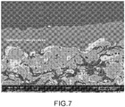
- the figure 7 is a micrograph of a section of this membrane.
- Example 3 describes the manufacture of an ultrafiltration membrane on a ceramic support.
- An aqueous sol of mesoporous silica at 10%, particle size 40 nm is injected into a thermal plasma under the same conditions as Example 1 and with the same means.
- Example 4 describes the manufacture of a phase separation membrane on a ceramic support.
- a porous substrate of alumina / titanium oxide is previously prepared by thermal spraying. Its porosity is 35% and its thickness 0.7 mm.
- An aqueous 5% silica sol with a particle size of 60 nm is mixed with 7.5% by weight of a monodisperse alumina powder having a particle size of 150 nm. This mixture is injected into a thermal plasma under the same conditions as Example 1 and with the same means. A deposit of 30 .mu.m thick and 30 nm porometry is obtained.
- the supported membrane is immersed in water at 80 ° C for 5h, then baked at 110 ° C for 10h. It is then dipped in a fluorinated solvent containing 1% of a fluoroalkoxysilane derivative (CF 3 (CH 2 ) 5 S i (OCH 3 ) 3 for 48 h)
- CF 3 (CH 2 ) 5 S i (OCH 3 ) 3 for 48 h A heat treatment at 130 ° C. for 1 h 30 creates a covalent bond between the silane and the metal oxide forming the membrane
- the membrane is thus hydrophobic
- the contact angle of a drop of water is close to 110 ° C.
- the membrane holds the water up to high pressures (> 10 bar) but remains permeable to gases.
- aqueous sol with 4% mesoporous silica of particle size between 20 and 40 nm is projected onto porous ceramic substrates identical to those of Example 2 and on a wafer wafer for micrographic analysis.
- the size of the mesopores of the initial particles is 2 and 3 nm in diameter. These mesopores adopt a hexagonal structure P6m .
- the figure 9 shows a micrograph obtained by transmission electron microscopy of the mesoporous soil deposit on the silicon wafer.
- the particles remain identifiable and are differentiated from each other, but that when we compare their initial form (see Fig. 4 ), they present dendrites on the periphery. This corresponds to a partial melting on the surface of the material, in this case silica.
- the interior of the particle remains in its original state as evidenced by the micrograph of the figure 9 : the mesoporous structure is preserved.
- a mesoporous particle (A), a network of mesopores (B) and dendrites (C) are identified.
Landscapes
- Chemical & Material Sciences (AREA)
- Engineering & Computer Science (AREA)
- Ceramic Engineering (AREA)
- Materials Engineering (AREA)
- Organic Chemistry (AREA)
- Chemical Kinetics & Catalysis (AREA)
- Structural Engineering (AREA)
- Inorganic Chemistry (AREA)
- Plasma & Fusion (AREA)
- Physics & Mathematics (AREA)
- Mechanical Engineering (AREA)
- Metallurgy (AREA)
- Manufacturing & Machinery (AREA)
- Dispersion Chemistry (AREA)
- Electrochemistry (AREA)
- Physical Or Chemical Processes And Apparatus (AREA)
- Oxygen, Ozone, And Oxides In General (AREA)
- Coating By Spraying Or Casting (AREA)
Claims (30)
- Verfahren zur Herstellung wenigstens einer nanoporösen Schicht aus Nanopartikeln, ausgewählt unter den Metalloxid-Nanopartikeln, den Nanopartikeln von metallischen Oxiden, und den Mischungen von diesen, auf einer Oberfläche eines Substrats, bei dem man wenigstens ein ein Lösungsmittel umfassendes kolloidales Sol, in dem die genannten Nanopartikel verteilt und stabilisiert sind, in einen thermischen Plasmastrahl einspritzt, der die genannten Nanopartikel auf die genannte Oberfläche schleudert ; wobei die genannte nanoporöse Schicht eine Porometrie bzw. Porengröße von 1 bis 500 nm, bevorzugt von 1 bis 100 nm, noch bevorzugter von 1 bis 50 nm aufweist, wobei die Nanopartikel direkt in dem im Laufe ihrer Synthese benutzten Lösungsmittel stabilisiert werden, auf diese Weise das Sol bildend, oder später peptisiert werden, wenn sie durch Fällung synthetisiert werden,
dadurch gekennzeichnet, dass das Sol in eine kalte Zone des Plasmas eingespritzt wird, in der eine Temperatur von 3000 bis 4000 K herrscht, und das Lösungsmittel des genannten Sols ausgewählt wird unter den Alkoholen wie etwa den alipathischen Alkoholen von 1 bis 5C wie das Ethanol oder das Methanol. - Verfahren nach Anspruch 1, bei dem die Nanopartikel eine Größe von 1 bis 500 nm, bevorzugt von 1 bis 100 nm, noch bevorzugter von 1 bis 50 nm haben.
- Verfahren nach einem der vorhergehenden Ansprüche, bei dem die Nanopartikel eine auf eine oder mehrere Spitzenwerte zentrierte Granulometrie haben.
- Verfahren nach einem der vorhergehenden Ansprüche, bei dem das oder die metallischen Oxide ausgewählt werden unter SiO2, ZrO2, TiO2, Ta2O5, HfO2, ThO2, SnO2, VO2, In2O3, Sb2O3, CeO2, ZnO, Nb2O5, V2O5, Al2O3, Sc2O3, Ce2O3, NiO, MgO, Y2O3, WO3, BaTiO3, Fe2O3, Fe3O4, Sr2O3, (PbZr)TiO3, (BaSr)TiO3, Co2O3, Cr2O3, Mn2O3, Mn3O4, Cr3O4, MnO2, und RuO2.
- Verfahren nach Anspruch 1, bei dem das Sol hergestellt wird durch Fällung im wässrigen Milieu oder durch Sol-Gel-Synthese im organischen Milieu, ausgehend von einem Nanopartikel-Präkursor.
- Verfahren nach Anspruch 5, bei dem der Nanopartikel-Präkursor ausgewählt wird in der Gruppe, die ein Metalloidsalz, ein Metallsalz, ein Metallalkoxid, oder eine Mischung von diesen umfasst.
- Verfahren nach Anspruch 6, bei dem das Metall oder Metalloid des Salzes oder des Alkoxids des Nanopartikel-Präkursors ausgewählt wird in der Gruppe, die umfasst: das Silicium, das Titan, das Zirkonium, das Hafnium, das Aluminium, das Tantal, das Niobium, das Cerium, das Nickel, das Eisen, das Zink, das Chrom, das Magnesium, das Kobalt, das Vanadium, das Baryum, das Strontium, das Zinn, das Scandium, das Indium, das Blei, das Yttrium, das Wolfram, das Mangan, das Gold, das Silber, das Platin, das Palladium, das Nickel, das Kupfer, das Kobalt, das Ruthenium, das Rhodium, das Europium und die anderen Seltenen Erden.
- Verfahren nach einem der vorhergehenden Ansprüche, bei dem das Sol ein Sol aus Nanopartikeln aus dem (den) Oxid(en) von Metall(en) wie etwa dem Zirkon, dem Siliciumdioxid, dem Titandioxid, dem Aluminiumoxid, dem Hafniumoxid ist.
- Verfahren nach Anspruch 1, bei dem die Nanopartikel insgesamt oder teilweise intrinsisch porös, makroporös, mikroporös, mesoporös oder mesostrukturiert sind.
- Verfahren nach einem der vorhergehenden Ansprüche, bei dem die Partikel insgesamt oder teilweise dichte Partikel sind und das Sol eventuell ein Texturierungsmittel und/oder ein Porenerzeugungsmittel wie etwa einen Oberflächenaktivstoff enthält.
- Verfahren nach einem der vorhergehenden Ansprüche, bei dem das Sol ein gemischtes Sol ist.
- Verfahren nach Anspruch 1, bei dem das Sol außerdem organische Moleküle umfasst.
- Verfahren nach Anspruch 12, bei dem die organischen Moleküle Moleküle zur Stabilisierung der Nanopartikel in dem Sol sind, und/oder Moleküle, welche die Nanopartikel funktionalisieren, und/oder Texturierungs- und/oder Porenerzeugungsmittel, sind.
- Verfahren nach einem der vorhergehenden Ansprüche, bei dem die nanoporöse Schicht eine Porosität größer oder gleich 20%, vorzugsweise größer oder gleich 50% hat.
- Verfahren nach einem der vorhergehenden Ansprüche, bei dem am Ende seiner Herstellung die genannte(n) nanoporöse(n) Partikelschicht(en) ganz oder teilweise funktionalisiert wird (werden) um ihr (ihnen) zum Beispiel eine Selektivität gegenüber einem Fluid zu verleihen.
- Verfahren nach Anspruch 15, bei dem die genannte(n) nanoporöse(n) Partikelschicht(en) durch kovalentes Pfropfen von Molekülen ganz oder teilweise funktionalisiert wird (werden).
- Verfahren nach Anspruch 16, bei dem die genannten gepfropften Moleküle hydrophobe Moleküle sind, zum Beispiel perfluorierte oder Alkyl-Moleküle.
- Verfahren nach einem der vorhergehenden Ansprüche, bei dem das Substrat ausgewählt wird unter den keramischen, metallischen Substraten und den thermosensiblen Substraten.
- Verfahren nach einem der vorhergehenden Ansprüche, bei dem die genannte Oberfläche des Substrats eine konvexe und/oder eine konkave Oberfläche ist, und/oder eine Oberfläche eines im Innern eines Teils befindlichen, Hohlraum ist.
- Verfahren nach Anspruch 1, bei dem das kolloide Sol tröpfchen- oder strahlförmig in den Plasmastrahl eingespritzt wird.
- Verfahren nach Anspruch 1, bei dem der Plasmastrahl ein Bogenplasmastrahl ist.
- Verfahren nach Anspruch 1, bei dem der Plasmastrahl derart ist, dass er eine partielle Fusion der eingespritzten Nanopartikel bewirkt.
- Verfahren nach Anspruch 1, bei dem das den Strahl bildende Plasma eine Temperatur von 5000 K bis 15000 K hat.
- Verfahren nach Anspruch 1, bei dem das den Strahl bildende Plasma eine Viskosität von 10-4 bis 5x10⁻⁴ kg/m.s aufweist.
- Verfahren nach Anspruch 1, bei dem der Plasmastrahl aus einem plasmagenen Gas, ausgewählt in der Ar, H2, He und N2 umfassenden Gruppe, erzeugt wird.
- Verfahren nach einem der vorhergehenden Ansprüche, bei dem man, simultan oder nicht, mehrere Sole in das Plasma einspritzt, wobei jede dieser Solen sich unterscheiden kann in Bezug auf ihre chemische Zusammensetzung und/oder ihre Granulometrie, und/oder ihre interne Struktur, und/oder ihr Lösungsmittel und/oder die Art der Zusatzstoffe.
- Verfahren nach einem der vorhergehenden Ansprüche, bei dem man außerdem in das Plasma, simultan mit den genannten Solen oder nicht, ein oder mehrere "trockene" nanometrische Pulver einspritzt.
- Verfahren nach einem der vorhergehenden Ansprüche, das auf eine selbe Substratoberfläche mehrere Male angewendet wird mit verschiedenen Solen mit unterschiedlicher Zusammensetzung und/oder Konzentration und/oder Partikelgröße und/oder Partikelstruktur und, eventuell, verschiedenen trockenen nanometrischen Pulvern, um sukzessive Schichten mit unterschiedlichen Zusammensetzungen und/oder unterschiedlichen Porositäten/Porometrien zu realisieren.
- Verfahren nach einem der vorhergehenden Ansprüche, bei dem das Substrat gebildet wird durch einen porösen Träger mit der Porosität ds, auf dem man eine oder mehrere Zwischenschichten 1i, 2i, ni von mittlerer abnehmender Porosität d1i, d2i, ..., dni, dni < d2i < d1i < ds, durch ein ein Sol oder eine Mischung aus Sol(en) und nanometrischem (nanometrischen) Pulver(n) umfassendes Spritzverfahren abscheidet, und man schließlich auf der letzten Zwischenschicht eine nanoporöse Schicht abscheidet, die eine mittlere Porosität dm < dni hat.
- Verfahren nach Anspruch 1, bei dem die nanoporöse Schicht eine Dicke von 0,1 µm bis 5 mm, vorzugsweise 0,1 µm bis 500 µm hat, zum Beispiel von 1 bis 100 µm, besser von 2 bis 50 µm.
Applications Claiming Priority (2)
| Application Number | Priority Date | Filing Date | Title |
|---|---|---|---|
| FR0651477A FR2900351B1 (fr) | 2006-04-26 | 2006-04-26 | Procede de preparation d'une couche nanoporeuse de nanoparticules et couche ainsi obtenue |
| PCT/EP2007/054076 WO2007122256A1 (fr) | 2006-04-26 | 2007-04-25 | Procede de preparation d'une couche nanoporeuse de nanoparticules et couche ainsi obtenue |
Publications (2)
| Publication Number | Publication Date |
|---|---|
| EP2010308A1 EP2010308A1 (de) | 2009-01-07 |
| EP2010308B1 true EP2010308B1 (de) | 2017-04-12 |
Family
ID=37451199
Family Applications (1)
| Application Number | Title | Priority Date | Filing Date |
|---|---|---|---|
| EP07728531.0A Active EP2010308B1 (de) | 2006-04-26 | 2007-04-25 | Verfahren zur herstellung einer nanoporösen nanopartikelschicht |
Country Status (5)
| Country | Link |
|---|---|
| US (1) | US8137442B2 (de) |
| EP (1) | EP2010308B1 (de) |
| JP (1) | JP5542431B2 (de) |
| FR (1) | FR2900351B1 (de) |
| WO (1) | WO2007122256A1 (de) |
Families Citing this family (86)
| Publication number | Priority date | Publication date | Assignee | Title |
|---|---|---|---|---|
| FR2877015B1 (fr) * | 2004-10-21 | 2007-10-26 | Commissariat Energie Atomique | Revetement nanostructure et procede de revetement. |
| US8431509B2 (en) | 2007-10-30 | 2013-04-30 | Cerahelix, Inc. | Structure for molecular separations |
| US20090280262A1 (en) * | 2008-05-08 | 2009-11-12 | Chung Yuan Christian University | Method for forming composite membrane with porous coating layer and apparatus thereof |
| ES2365570B1 (es) * | 2008-11-26 | 2012-09-17 | Comercial De Utiles Y Moldes S.A. | Mecanismo de corredera para moldeo y expulsion de negativos en moldes de inyeccion de plastico |
| JP2012512280A (ja) * | 2008-12-17 | 2012-05-31 | ユニバーシティ オブ サウス オーストラリア | 活性ポリマーフィルム |
| US9072185B2 (en) * | 2009-07-30 | 2015-06-30 | Lockheed Martin Corporation | Copper nanoparticle application processes for low temperature printable, flexible/conformal electronics and antennas |
| US9011570B2 (en) | 2009-07-30 | 2015-04-21 | Lockheed Martin Corporation | Articles containing copper nanoparticles and methods for production and use thereof |
| DE102009037846A1 (de) * | 2009-08-18 | 2011-02-24 | Siemens Aktiengesellschaft | Partikelgefüllte Beschichtungen, Verfahren zur Herstellung und Verwendungen dazu |
| ES2930370T3 (es) | 2009-10-08 | 2022-12-09 | Delos Living Llc | Sistema de iluminación LED |
| KR101132127B1 (ko) * | 2009-12-21 | 2012-04-02 | 한국과학기술원 | 마이크로-나노 복합체를 가지는 친수성과 소수성의 조절이 가능한 소자 및 그 제조방법 |
| JP5845091B2 (ja) * | 2010-01-28 | 2016-01-20 | 株式会社豊田中央研究所 | 捕捉対象物質捕捉材、捕捉対象物質捕捉用フィルタ、液状有機化合物収容容器およびエンジンオイル |
| JP2011218310A (ja) * | 2010-04-12 | 2011-11-04 | Sumitomo Osaka Cement Co Ltd | 排ガス浄化フィルタ、排ガス浄化フィルタの製造方法 |
| US10259723B2 (en) | 2010-05-21 | 2019-04-16 | Znano Llc | Self-assembled surfactant structures |
| JP6031660B2 (ja) * | 2010-05-21 | 2016-11-24 | ゼットナノ エルエルシーzNano LLC | 自己集合界面活性剤構造 |
| US12384699B2 (en) | 2010-05-21 | 2025-08-12 | Crosstek Holding Company Llc | Self-assembled surfactant structures |
| WO2011149744A1 (en) * | 2010-05-25 | 2011-12-01 | Corning Incorporated | Cordierite membrane on a cordierite monolith |
| ITRM20100407A1 (it) * | 2010-07-22 | 2012-01-23 | Fabio Cipri | Membrane e procedimento per la loro realizzazione. |
| KR101040572B1 (ko) * | 2010-10-11 | 2011-06-16 | 대한민국 | 셀룰로오스 나노섬유를 이용한 다공성 분리막 및 그 제조방법 |
| US20120308775A1 (en) * | 2010-12-09 | 2012-12-06 | You Seung M | Hydrophilic surfaces and process for preparing |
| MX388775B (es) | 2011-05-04 | 2025-03-20 | Stewart Benson Averett | Composiciones fotocatalíticas de dióxido de titanio y sus usos. |
| CN103889562B (zh) * | 2011-05-27 | 2017-09-08 | 康奈尔大学 | 纳米粒子官能化的膜及其制备方法和用途 |
| US9365939B2 (en) * | 2011-05-31 | 2016-06-14 | Wisconsin Alumni Research Foundation | Nanoporous materials for reducing the overpotential of creating hydrogen by water electrolysis |
| KR101276240B1 (ko) | 2011-10-10 | 2013-06-20 | 인하대학교 산학협력단 | 오산화바나듐(v2o5)이 코팅된 이산화티타늄(tio2)분말의 제조방법 및 이에 따라 제조되는 오산화바나듐이 코팅된 이산화티타늄 분말 |
| CA2853670C (en) | 2011-10-27 | 2017-06-13 | Garmor, Inc. | Composite graphene structures |
| KR101164650B1 (ko) | 2011-11-30 | 2012-07-27 | 대한민국 | 셀룰로오스 나노섬유를 포함하는 이차전지용 다공성 분리막 및 그 제조방법 |
| US10124300B2 (en) * | 2012-02-28 | 2018-11-13 | Massachusetts Institute Of Technology | Flux-enhanced hierarchical porous membrane for oil-water nanoemulsion separation |
| US10384961B2 (en) * | 2012-02-28 | 2019-08-20 | Massachusetts Institute Of Technology | Hierarchical porous membrane for emulsion separation |
| GB201203430D0 (en) * | 2012-02-28 | 2012-04-11 | Univ Leicester | Chemical reaction |
| JP6194493B2 (ja) * | 2012-03-30 | 2017-09-13 | 株式会社ブイ・テクノロジー | 薄膜パターン形成方法 |
| US10279365B2 (en) * | 2012-04-27 | 2019-05-07 | Progressive Surface, Inc. | Thermal spray method integrating selected removal of particulates |
| US20130284203A1 (en) * | 2012-04-27 | 2013-10-31 | Progressive Surface, Inc. | Plasma spray apparatus integrating water cleaning |
| ES2781873T3 (es) | 2012-08-28 | 2020-09-08 | Delos Living Llc | Sistemas y métodos para mejorar el bienestar asociado con ambientes habitables |
| DE102012217617A1 (de) * | 2012-09-27 | 2014-03-27 | Siemens Aktiengesellschaft | Bauteil mit einer Schicht sowie Verfahren zu dessen Herstellung |
| DE102012021222B4 (de) * | 2012-10-27 | 2015-02-05 | Forschungszentrum Jülich GmbH | Verfahren zur Herstellung einer nanoporösen Schicht auf einem Substrat |
| FR2999457B1 (fr) * | 2012-12-18 | 2015-01-16 | Commissariat Energie Atomique | Procede de revetement d'un substrat par un materiau abradable ceramique, et revetement ainsi obtenu. |
| FR3000408B1 (fr) * | 2013-01-03 | 2015-02-27 | Commissariat Energie Atomique | Procede de realisation d'un filtre destine a la filtration de nanoparticules, filtre obtenu et procede de collecte et d'analyse quantitative de nanoparticules associe. |
| CA2903987C (en) | 2013-03-08 | 2018-05-01 | University Of Central Florida Research Foundation, Inc. | Large scale oxidized graphene production for industrial applications |
| EP2964573A4 (de) | 2013-03-08 | 2016-11-02 | Garmor Inc | Grapheneinschluss in einem wirt |
| CN103172030B (zh) * | 2013-03-22 | 2015-04-15 | 清华大学深圳研究生院 | 氧化物粉体及其制备方法、催化剂、以及催化剂载体 |
| US9085120B2 (en) | 2013-08-26 | 2015-07-21 | International Business Machines Corporation | Solid state nanopore devices for nanopore applications to improve the nanopore sensitivity and methods of manufacture |
| WO2015080780A2 (en) * | 2013-09-10 | 2015-06-04 | Amastan Technologies Llc | Metal oxide nanopowders as alternate precursor source to nitrates |
| CA2940766A1 (en) | 2014-02-28 | 2015-09-03 | Delos Living Llc | Systems, methods and articles for enhancing wellness associated with habitable environments |
| US20150273518A1 (en) * | 2014-03-25 | 2015-10-01 | Liquiglide, Inc. | Spray Processes and Methods for Forming Liquid-Impregnated Surfaces |
| US10730798B2 (en) * | 2014-05-07 | 2020-08-04 | Applied Materials, Inc. | Slurry plasma spray of plasma resistant ceramic coating |
| KR101602561B1 (ko) * | 2014-06-03 | 2016-03-15 | 고려대학교 산학협력단 | 로듐 첨가 wo3를 이용한 가스 센서 및 그 제조 방법 |
| US10068683B1 (en) | 2014-06-06 | 2018-09-04 | Southwire Company, Llc | Rare earth materials as coating compositions for conductors |
| EP3160233A4 (de) | 2014-06-23 | 2018-03-07 | Well Shield LLC | Reduktion von infektionen in der krankenpflege mit fotokatalytischen zusammensetzungen |
| ES2558183B1 (es) * | 2014-07-01 | 2016-11-11 | Consejo Superior De Investigaciones Científicas (Csic) | Capa catalítica y su uso en membranas permeables al oxigeno |
| US9828290B2 (en) | 2014-08-18 | 2017-11-28 | Garmor Inc. | Graphite oxide entrainment in cement and asphalt composite |
| BR112017005827A2 (pt) * | 2014-10-07 | 2018-01-30 | Basf Corp | dispersão coloidal, método de fazer uma dispersão coloidal e catalisador |
| CA2967578C (en) * | 2014-12-04 | 2021-03-16 | Progressive Surface, Inc. | Thermal spray method integrating selected removal of particulates |
| EP3245631A4 (de) | 2015-01-13 | 2018-06-27 | Delos Living, LLC | Systeme, verfahren und artikel zur überwachung und steigerung des menschlichen wohlbefindens |
| JP6484348B2 (ja) | 2015-03-13 | 2019-03-13 | ユニバーシティ オブ セントラル フロリダ リサーチ ファウンデーション,インコーポレイテッド | ホスト中でのグラフェンナノ粒子の均一な分散 |
| WO2016154057A1 (en) | 2015-03-23 | 2016-09-29 | Garmor Inc. | Engineered composite structure using graphene oxide |
| JP6603729B2 (ja) * | 2015-03-27 | 2019-11-06 | ユニバーシティ オブ セントラル フロリダ リサーチ ファウンデーション,インコーポレイテッド | 修復及び保護コーティングの溶射 |
| JP6563029B2 (ja) | 2015-04-13 | 2019-08-21 | ガーマー インク.Garmor, Inc. | コンクリート又はアスファルトなどのホスト中の酸化グラファイト強化繊維 |
| US11482348B2 (en) | 2015-06-09 | 2022-10-25 | Asbury Graphite Of North Carolina, Inc. | Graphite oxide and polyacrylonitrile based composite |
| WO2017053204A1 (en) | 2015-09-21 | 2017-03-30 | Garmor Inc. | Low-cost, high-performance composite bipolar plate |
| US9770688B2 (en) * | 2015-10-22 | 2017-09-26 | King Fahd University Of Petroleum And Minerals | Si—Y nanocomposite membrane and methods of making and use thereof |
| CN105664734A (zh) * | 2016-03-09 | 2016-06-15 | 刘平 | 一种用于市政污水处理的滤膜及其制备方法和应用 |
| EP3228381B8 (de) * | 2016-04-08 | 2023-08-30 | Aqua Free GmbH | Verfahren zur herstellung einer beschichteten polymermembran zur filtration von wasser |
| US10258977B2 (en) * | 2016-04-18 | 2019-04-16 | Muhammad Akhyar Furrukh | Development of nanofiltration system with La/SnO2—TiO2 nanoparticles |
| CN106215711A (zh) * | 2016-08-23 | 2016-12-14 | 南京工业大学 | 一种具有高水热稳定性的透h2膜的制备方法 |
| WO2018039433A1 (en) | 2016-08-24 | 2018-03-01 | Delos Living Llc | Systems, methods and articles for enhancing wellness associated with habitable environments |
| WO2018081413A1 (en) | 2016-10-26 | 2018-05-03 | Garmor Inc. | Additive coated particles for low high performance materials |
| FR3059910B1 (fr) | 2016-12-14 | 2019-02-01 | IFP Energies Nouvelles | Procede pour le traitement d'un liquide aqueux au moyen d'un filtre determine en fonction de la tension interfaciale du liquide |
| US11313040B2 (en) * | 2017-03-24 | 2022-04-26 | Embraco Indústria De Compressores E Soluçôes Em Refrigeraçâo Ltda. | Plasma-assisted process of ceramization of polymer precursor on surface, surface comprising ceramic polymer |
| WO2018221995A1 (ko) * | 2017-06-02 | 2018-12-06 | 서강대학교산학협력단 | 소수성 멤브레인 및 이를 포함하는 장치 |
| WO2019046580A1 (en) | 2017-08-30 | 2019-03-07 | Delos Living Llc | SYSTEMS, METHODS AND ARTICLES FOR EVALUATING AND / OR IMPROVING HEALTH AND WELL-BEING |
| WO2019136272A1 (en) | 2018-01-04 | 2019-07-11 | University Of Washington | Nanoporous selective sol-gel ceramic membranes, selective -membrane structures, and related methods |
| JP6543753B2 (ja) * | 2018-08-07 | 2019-07-10 | アマスタン・テクノロジーズ・エル・エル・シー | プラズマを使用して固体材料および材料の溶液前駆体液滴を高密度化および球状化する方法 |
| US11649977B2 (en) | 2018-09-14 | 2023-05-16 | Delos Living Llc | Systems and methods for air remediation |
| FR3087451B1 (fr) | 2018-10-17 | 2020-11-06 | Commissariat Energie Atomique | Procede de fabrication d'un monocristal par croissance en solution permettant un piegeage de cristaux parasites |
| US11844163B2 (en) | 2019-02-26 | 2023-12-12 | Delos Living Llc | Method and apparatus for lighting in an office environment |
| US11898898B2 (en) | 2019-03-25 | 2024-02-13 | Delos Living Llc | Systems and methods for acoustic monitoring |
| US11791061B2 (en) | 2019-09-12 | 2023-10-17 | Asbury Graphite North Carolina, Inc. | Conductive high strength extrudable ultra high molecular weight polymer graphene oxide composite |
| CN112774457B (zh) * | 2019-11-01 | 2022-08-19 | 中国石油化工股份有限公司 | 一种聚合物微滤膜及其制备方法和用途 |
| CN111517766A (zh) * | 2020-05-11 | 2020-08-11 | 镇江华鑫磨具有限公司 | 多孔陶瓷过滤板制造方法 |
| CN112287296B (zh) * | 2020-10-13 | 2023-05-26 | 北京师范大学 | 一种基于双波段闪烁仪的地表水热通量测算方法 |
| CN113913723B (zh) * | 2021-12-14 | 2022-02-22 | 矿冶科技集团有限公司 | 一种微米级多孔结构热障涂层粉末及其制备方法 |
| KR102755734B1 (ko) * | 2022-02-07 | 2025-01-21 | 주식회사 월덱스 | 플라즈마를 이용한 증착방법 |
| KR102755738B1 (ko) * | 2022-02-07 | 2025-01-21 | 주식회사 월덱스 | 플라즈마를 이용한 증착장치 |
| JP2023128827A (ja) * | 2022-03-04 | 2023-09-14 | 国立大学法人長岡技術科学大学 | 耐火断熱膜およびその製造方法 |
| CN116675529B (zh) * | 2023-05-30 | 2025-07-15 | 安徽工程大学 | 一种钛酸铋钠-钛酸锶高储能无铅陶瓷材料及其制备方法 |
| CN117643802B (zh) * | 2023-08-09 | 2026-04-17 | 南京中医药大学 | 一种陶瓷膜及其制备方法 |
| CN119730038A (zh) * | 2024-12-24 | 2025-03-28 | 安徽大学 | 一种多孔陶瓷基板电化学气体传感器的制备方法与应用 |
Citations (2)
| Publication number | Priority date | Publication date | Assignee | Title |
|---|---|---|---|---|
| WO2006034674A1 (de) * | 2004-09-30 | 2006-04-06 | Forschungszentrum Jülich GmbH | Herstellung einer gasdichten, kristallinen mullit schicht mit hilfe eines thermischen spritzverfahrens |
| WO2006043006A1 (fr) * | 2004-10-21 | 2006-04-27 | Commissariat A L'energie Atomique | Revetement nanostructure et procede de revetement |
Family Cites Families (16)
| Publication number | Priority date | Publication date | Assignee | Title |
|---|---|---|---|---|
| JPS5141017B2 (de) * | 1972-12-26 | 1976-11-08 | ||
| US4982067A (en) | 1988-11-04 | 1991-01-01 | Marantz Daniel Richard | Plasma generating apparatus and method |
| US5032568A (en) | 1989-09-01 | 1991-07-16 | Regents Of The University Of Minnesota | Deposition of superconducting thick films by spray inductively coupled plasma method |
| FR2682486B1 (fr) | 1991-10-15 | 1993-11-12 | Commissariat A Energie Atomique | Miroir dielectrique interferentiel et procede de fabrication d'un tel miroir. |
| US5698266A (en) | 1993-04-05 | 1997-12-16 | Commissariat A L'energie Atomique | Process for the production of thin coatings having optical and abrasion resistance properties |
| FR2703791B1 (fr) | 1993-04-05 | 1995-05-19 | Commissariat Energie Atomique | Procédé de fabrication de couches minces présentant des propriétés optiques et des propriétés de résistance à l'abrasion . |
| FR2707763B1 (fr) | 1993-07-16 | 1995-08-11 | Commissariat Energie Atomique | Matériau composite à indice de réfraction élevé, procédé de fabrication de ce matériau composite et matériau optiquement actif comprenant ce matériau composite. |
| US5413821A (en) | 1994-07-12 | 1995-05-09 | Iowa State University Research Foundation, Inc. | Process for depositing Cr-bearing layer |
| US5609921A (en) | 1994-08-26 | 1997-03-11 | Universite De Sherbrooke | Suspension plasma spray |
| CN1195884C (zh) * | 1995-11-13 | 2005-04-06 | 康涅狄格大学 | 用于热喷涂的纳米结构的进料 |
| US6447848B1 (en) * | 1995-11-13 | 2002-09-10 | The United States Of America As Represented By The Secretary Of The Navy | Nanosize particle coatings made by thermally spraying solution precursor feedstocks |
| JPH10130848A (ja) * | 1996-10-25 | 1998-05-19 | Seiko Epson Corp | 酸化物の成膜方法 |
| EP1134302A1 (de) * | 2000-03-17 | 2001-09-19 | Consorzio Interuniversitario per lo Sviluppo dei Sistemi a Grande Interfase, C.S.G.I | Verfahren zur Herstellung von festen nanostrukturierten Pulvern und Filmen aus Nano-Teilchen durch thermisches Spritzen einer kompartimentierten Lösung |
| JP4103470B2 (ja) * | 2002-06-28 | 2008-06-18 | Toto株式会社 | 多孔質複合構造物の作製方法 |
| US7563503B2 (en) * | 2003-01-10 | 2009-07-21 | The University Of Connecticut | Coatings, materials, articles, and methods of making thereof |
| US20070218564A1 (en) * | 2004-04-27 | 2007-09-20 | Koninklijke Philips Electronic N.V. | Use of a Composite or Composition of Diamond and Other Material for Analysis of Analytes |
-
2006
- 2006-04-26 FR FR0651477A patent/FR2900351B1/fr not_active Expired - Lifetime
-
2007
- 2007-04-25 EP EP07728531.0A patent/EP2010308B1/de active Active
- 2007-04-25 US US12/298,057 patent/US8137442B2/en not_active Expired - Fee Related
- 2007-04-25 JP JP2009507074A patent/JP5542431B2/ja not_active Expired - Fee Related
- 2007-04-25 WO PCT/EP2007/054076 patent/WO2007122256A1/fr not_active Ceased
Patent Citations (2)
| Publication number | Priority date | Publication date | Assignee | Title |
|---|---|---|---|---|
| WO2006034674A1 (de) * | 2004-09-30 | 2006-04-06 | Forschungszentrum Jülich GmbH | Herstellung einer gasdichten, kristallinen mullit schicht mit hilfe eines thermischen spritzverfahrens |
| WO2006043006A1 (fr) * | 2004-10-21 | 2006-04-27 | Commissariat A L'energie Atomique | Revetement nanostructure et procede de revetement |
Also Published As
| Publication number | Publication date |
|---|---|
| FR2900351B1 (fr) | 2008-06-13 |
| US8137442B2 (en) | 2012-03-20 |
| JP5542431B2 (ja) | 2014-07-09 |
| EP2010308A1 (de) | 2009-01-07 |
| US20090241496A1 (en) | 2009-10-01 |
| WO2007122256A1 (fr) | 2007-11-01 |
| JP2009534183A (ja) | 2009-09-24 |
| FR2900351A1 (fr) | 2007-11-02 |
Similar Documents
| Publication | Publication Date | Title |
|---|---|---|
| EP2010308B1 (de) | Verfahren zur herstellung einer nanoporösen nanopartikelschicht | |
| EP1802783B1 (de) | Beschichtungsverfahren | |
| EP2155923B1 (de) | Verfahren und vorrichtung zur herstellung eines mehrschichtigen überzugs auf einem substrat | |
| EP0188950B1 (de) | Verfahren zur Herstellung poröser und permeabler anorganischer Membranen | |
| Brezesinski et al. | Evaporation‐Induced Self‐Assembly (EISA) at Its Limit: Ultrathin, Crystalline Patterns by Templating of Micellar Monolayers | |
| EP2314734A1 (de) | Verfahren zur Herstellung poröser Metalloxidfilmen mittels vorlagenunterstützter elektrostatischer Sprayablagerung | |
| EP2035134A1 (de) | Verfahren zur synthese von beschichteten organischen oder anorganischen teilchen | |
| FR2984305A1 (fr) | Procede de preparation d'un sol-gel d'au moins trois sels de metaux et mise en oeuvre du procede pour preparer une membrane ceramique | |
| KR100823895B1 (ko) | 서로 다른 크기의 무기물 입자를 포함하는 초소수성코팅필름, 코팅조성물 및 코팅층의 형성방법 | |
| EP2935641B1 (de) | Verfahren zur beschichtung eines substrats mit einem abreibbaren keramischen material | |
| WO1995021950A1 (fr) | Materiau electroactive, sa preparation et son utilisation pour l'obtention d'elements cathodiques | |
| Khapli et al. | Supercritical CO2 based processing of amorphous fluoropolymer Teflon-AF: surfactant-free dispersions and superhydrophobic films | |
| Shahravan et al. | Controlled manipulation of wetting characteristics of nanoparticles with dry-based plasma polymerization method | |
| EP2547637A1 (de) | Verfahren zur herstellung poröser nanostrukturierter keramikdoppelschichten, auf diese weise hergestellte keramikdoppelschichten und ihre verwendung | |
| EP3696203B1 (de) | Herstellungsverfahren von hybriden metall-/polymer-nanopartikeln mit geringer grössenverteilung durch polymerisation in mini-emulsionen | |
| Kim et al. | Tuning Hydrophobicity with Honeycomb Surface Structure and Hydrophilicity with CF 4 Plasma Etching for Aerosol‐Deposited Titania Films | |
| Nazarov et al. | Modified polymer substrates for the formation of submicron particle ensembles from colloidal solution | |
| CA3199826A1 (en) | Method for the manufacture of a self-standing graphene oxide or reduced graphene oxide film | |
| EP1644300B1 (de) | Verfahren zur herstellung von schichten von yttriumoxid dotiertes zirkonoxid | |
| Atkinson et al. | Aerosol impaction-driven assembly produces evenly dispersed nanoparticle coating on polymeric water treatment membranes | |
| Shi et al. | Nanostructured ceramic thin films and membranes by wet chemical processing methods |
Legal Events
| Date | Code | Title | Description |
|---|---|---|---|
| PUAI | Public reference made under article 153(3) epc to a published international application that has entered the european phase |
Free format text: ORIGINAL CODE: 0009012 |
|
| 17P | Request for examination filed |
Effective date: 20081028 |
|
| AK | Designated contracting states |
Kind code of ref document: A1 Designated state(s): AT BE BG CH CY CZ DE DK EE ES FI FR GB GR HU IE IS IT LI LT LU LV MC MT NL PL PT RO SE SI SK TR |
|
| AX | Request for extension of the european patent |
Extension state: AL BA HR MK RS |
|
| RIN1 | Information on inventor provided before grant (corrected) |
Inventor name: VALLE, KARINE Inventor name: BELLEVILLE, PHILIPPE Inventor name: TOULC'HOAT, JOEL Inventor name: BOSCHER, CHRISTOPHE Inventor name: PINTAULT, BRUNO Inventor name: GUENADOU, DAVID Inventor name: BIANCHI, LUC |
|
| 17Q | First examination report despatched |
Effective date: 20091203 |
|
| RAP1 | Party data changed (applicant data changed or rights of an application transferred) |
Owner name: COMMISSARIAT A L'ENERGIE ATOMIQUE ET AUX ENERGIES |
|
| DAX | Request for extension of the european patent (deleted) | ||
| REG | Reference to a national code |
Ref country code: DE Ref legal event code: R079 Ref document number: 602007050570 Country of ref document: DE Free format text: PREVIOUS MAIN CLASS: B01D0071020000 Ipc: B01D0067000000 |
|
| GRAP | Despatch of communication of intention to grant a patent |
Free format text: ORIGINAL CODE: EPIDOSNIGR1 |
|
| STAA | Information on the status of an ep patent application or granted ep patent |
Free format text: STATUS: GRANT OF PATENT IS INTENDED |
|
| RIC1 | Information provided on ipc code assigned before grant |
Ipc: B01D 67/00 20060101AFI20161116BHEP Ipc: C04B 41/49 20060101ALI20161116BHEP Ipc: C04B 41/52 20060101ALI20161116BHEP Ipc: C23C 4/134 20160101ALI20161116BHEP Ipc: C23C 4/12 20060101ALI20161116BHEP Ipc: C04B 35/47 20060101ALI20161116BHEP Ipc: C23C 4/11 20160101ALI20161116BHEP Ipc: B01D 61/14 20060101ALN20161116BHEP Ipc: C04B 111/00 20060101ALI20161116BHEP Ipc: C04B 41/89 20060101ALI20161116BHEP Ipc: C04B 41/45 20060101ALI20161116BHEP Ipc: B01D 69/12 20060101ALI20161116BHEP Ipc: B01D 71/02 20060101ALI20161116BHEP Ipc: C04B 35/00 20060101ALI20161116BHEP Ipc: C04B 41/50 20060101ALI20161116BHEP Ipc: C04B 41/00 20060101ALI20161116BHEP Ipc: B01D 61/02 20060101ALN20161116BHEP Ipc: C04B 35/46 20060101ALI20161116BHEP Ipc: C04B 41/87 20060101ALI20161116BHEP Ipc: C04B 41/85 20060101ALI20161116BHEP Ipc: B01D 69/02 20060101ALI20161116BHEP |
|
| INTG | Intention to grant announced |
Effective date: 20161202 |
|
| GRAS | Grant fee paid |
Free format text: ORIGINAL CODE: EPIDOSNIGR3 |
|
| GRAA | (expected) grant |
Free format text: ORIGINAL CODE: 0009210 |
|
| STAA | Information on the status of an ep patent application or granted ep patent |
Free format text: STATUS: THE PATENT HAS BEEN GRANTED |
|
| AK | Designated contracting states |
Kind code of ref document: B1 Designated state(s): AT BE BG CH CY CZ DE DK EE ES FI FR GB GR HU IE IS IT LI LT LU LV MC MT NL PL PT RO SE SI SK TR |
|
| REG | Reference to a national code |
Ref country code: GB Ref legal event code: FG4D Free format text: NOT ENGLISH |
|
| REG | Reference to a national code |
Ref country code: CH Ref legal event code: EP |
|
| REG | Reference to a national code |
Ref country code: IE Ref legal event code: FG4D Free format text: LANGUAGE OF EP DOCUMENT: FRENCH |
|
| REG | Reference to a national code |
Ref country code: AT Ref legal event code: REF Ref document number: 883296 Country of ref document: AT Kind code of ref document: T Effective date: 20170515 |
|
| REG | Reference to a national code |
Ref country code: DE Ref legal event code: R096 Ref document number: 602007050570 Country of ref document: DE |
|
| REG | Reference to a national code |
Ref country code: FR Ref legal event code: PLFP Year of fee payment: 11 |
|
| REG | Reference to a national code |
Ref country code: NL Ref legal event code: MP Effective date: 20170412 |
|
| REG | Reference to a national code |
Ref country code: LT Ref legal event code: MG4D |
|
| REG | Reference to a national code |
Ref country code: AT Ref legal event code: MK05 Ref document number: 883296 Country of ref document: AT Kind code of ref document: T Effective date: 20170412 |
|
| PG25 | Lapsed in a contracting state [announced via postgrant information from national office to epo] |
Ref country code: NL Free format text: LAPSE BECAUSE OF FAILURE TO SUBMIT A TRANSLATION OF THE DESCRIPTION OR TO PAY THE FEE WITHIN THE PRESCRIBED TIME-LIMIT Effective date: 20170412 |
|
| PG25 | Lapsed in a contracting state [announced via postgrant information from national office to epo] |
Ref country code: GR Free format text: LAPSE BECAUSE OF FAILURE TO SUBMIT A TRANSLATION OF THE DESCRIPTION OR TO PAY THE FEE WITHIN THE PRESCRIBED TIME-LIMIT Effective date: 20170713 Ref country code: ES Free format text: LAPSE BECAUSE OF FAILURE TO SUBMIT A TRANSLATION OF THE DESCRIPTION OR TO PAY THE FEE WITHIN THE PRESCRIBED TIME-LIMIT Effective date: 20170412 Ref country code: AT Free format text: LAPSE BECAUSE OF FAILURE TO SUBMIT A TRANSLATION OF THE DESCRIPTION OR TO PAY THE FEE WITHIN THE PRESCRIBED TIME-LIMIT Effective date: 20170412 Ref country code: LT Free format text: LAPSE BECAUSE OF FAILURE TO SUBMIT A TRANSLATION OF THE DESCRIPTION OR TO PAY THE FEE WITHIN THE PRESCRIBED TIME-LIMIT Effective date: 20170412 Ref country code: FI Free format text: LAPSE BECAUSE OF FAILURE TO SUBMIT A TRANSLATION OF THE DESCRIPTION OR TO PAY THE FEE WITHIN THE PRESCRIBED TIME-LIMIT Effective date: 20170412 |
|
| PG25 | Lapsed in a contracting state [announced via postgrant information from national office to epo] |
Ref country code: SE Free format text: LAPSE BECAUSE OF FAILURE TO SUBMIT A TRANSLATION OF THE DESCRIPTION OR TO PAY THE FEE WITHIN THE PRESCRIBED TIME-LIMIT Effective date: 20170412 Ref country code: PL Free format text: LAPSE BECAUSE OF FAILURE TO SUBMIT A TRANSLATION OF THE DESCRIPTION OR TO PAY THE FEE WITHIN THE PRESCRIBED TIME-LIMIT Effective date: 20170412 Ref country code: LV Free format text: LAPSE BECAUSE OF FAILURE TO SUBMIT A TRANSLATION OF THE DESCRIPTION OR TO PAY THE FEE WITHIN THE PRESCRIBED TIME-LIMIT Effective date: 20170412 Ref country code: IS Free format text: LAPSE BECAUSE OF FAILURE TO SUBMIT A TRANSLATION OF THE DESCRIPTION OR TO PAY THE FEE WITHIN THE PRESCRIBED TIME-LIMIT Effective date: 20170812 Ref country code: BG Free format text: LAPSE BECAUSE OF FAILURE TO SUBMIT A TRANSLATION OF THE DESCRIPTION OR TO PAY THE FEE WITHIN THE PRESCRIBED TIME-LIMIT Effective date: 20170712 |
|
| REG | Reference to a national code |
Ref country code: CH Ref legal event code: PL |
|
| REG | Reference to a national code |
Ref country code: DE Ref legal event code: R097 Ref document number: 602007050570 Country of ref document: DE |
|
| REG | Reference to a national code |
Ref country code: IE Ref legal event code: MM4A |
|
| PG25 | Lapsed in a contracting state [announced via postgrant information from national office to epo] |
Ref country code: EE Free format text: LAPSE BECAUSE OF FAILURE TO SUBMIT A TRANSLATION OF THE DESCRIPTION OR TO PAY THE FEE WITHIN THE PRESCRIBED TIME-LIMIT Effective date: 20170412 Ref country code: DK Free format text: LAPSE BECAUSE OF FAILURE TO SUBMIT A TRANSLATION OF THE DESCRIPTION OR TO PAY THE FEE WITHIN THE PRESCRIBED TIME-LIMIT Effective date: 20170412 Ref country code: RO Free format text: LAPSE BECAUSE OF FAILURE TO SUBMIT A TRANSLATION OF THE DESCRIPTION OR TO PAY THE FEE WITHIN THE PRESCRIBED TIME-LIMIT Effective date: 20170412 Ref country code: MC Free format text: LAPSE BECAUSE OF FAILURE TO SUBMIT A TRANSLATION OF THE DESCRIPTION OR TO PAY THE FEE WITHIN THE PRESCRIBED TIME-LIMIT Effective date: 20170412 Ref country code: SK Free format text: LAPSE BECAUSE OF FAILURE TO SUBMIT A TRANSLATION OF THE DESCRIPTION OR TO PAY THE FEE WITHIN THE PRESCRIBED TIME-LIMIT Effective date: 20170412 Ref country code: CZ Free format text: LAPSE BECAUSE OF FAILURE TO SUBMIT A TRANSLATION OF THE DESCRIPTION OR TO PAY THE FEE WITHIN THE PRESCRIBED TIME-LIMIT Effective date: 20170412 |
|
| PLBE | No opposition filed within time limit |
Free format text: ORIGINAL CODE: 0009261 |
|
| STAA | Information on the status of an ep patent application or granted ep patent |
Free format text: STATUS: NO OPPOSITION FILED WITHIN TIME LIMIT |
|
| PG25 | Lapsed in a contracting state [announced via postgrant information from national office to epo] |
Ref country code: LU Free format text: LAPSE BECAUSE OF NON-PAYMENT OF DUE FEES Effective date: 20170425 Ref country code: CH Free format text: LAPSE BECAUSE OF NON-PAYMENT OF DUE FEES Effective date: 20170430 Ref country code: LI Free format text: LAPSE BECAUSE OF NON-PAYMENT OF DUE FEES Effective date: 20170430 |
|
| 26N | No opposition filed |
Effective date: 20180115 |
|
| REG | Reference to a national code |
Ref country code: BE Ref legal event code: MM Effective date: 20170430 |
|
| REG | Reference to a national code |
Ref country code: FR Ref legal event code: PLFP Year of fee payment: 12 |
|
| PG25 | Lapsed in a contracting state [announced via postgrant information from national office to epo] |
Ref country code: IE Free format text: LAPSE BECAUSE OF NON-PAYMENT OF DUE FEES Effective date: 20170425 |
|
| PG25 | Lapsed in a contracting state [announced via postgrant information from national office to epo] |
Ref country code: SI Free format text: LAPSE BECAUSE OF FAILURE TO SUBMIT A TRANSLATION OF THE DESCRIPTION OR TO PAY THE FEE WITHIN THE PRESCRIBED TIME-LIMIT Effective date: 20170412 Ref country code: BE Free format text: LAPSE BECAUSE OF NON-PAYMENT OF DUE FEES Effective date: 20170430 |
|
| PG25 | Lapsed in a contracting state [announced via postgrant information from national office to epo] |
Ref country code: MT Free format text: LAPSE BECAUSE OF FAILURE TO SUBMIT A TRANSLATION OF THE DESCRIPTION OR TO PAY THE FEE WITHIN THE PRESCRIBED TIME-LIMIT Effective date: 20170412 |
|
| PG25 | Lapsed in a contracting state [announced via postgrant information from national office to epo] |
Ref country code: HU Free format text: LAPSE BECAUSE OF FAILURE TO SUBMIT A TRANSLATION OF THE DESCRIPTION OR TO PAY THE FEE WITHIN THE PRESCRIBED TIME-LIMIT; INVALID AB INITIO Effective date: 20070425 |
|
| PGFP | Annual fee paid to national office [announced via postgrant information from national office to epo] |
Ref country code: DE Payment date: 20190415 Year of fee payment: 13 Ref country code: IT Payment date: 20190411 Year of fee payment: 13 |
|
| PG25 | Lapsed in a contracting state [announced via postgrant information from national office to epo] |
Ref country code: CY Free format text: LAPSE BECAUSE OF NON-PAYMENT OF DUE FEES Effective date: 20170412 |
|
| PGFP | Annual fee paid to national office [announced via postgrant information from national office to epo] |
Ref country code: GB Payment date: 20190424 Year of fee payment: 13 |
|
| PG25 | Lapsed in a contracting state [announced via postgrant information from national office to epo] |
Ref country code: TR Free format text: LAPSE BECAUSE OF FAILURE TO SUBMIT A TRANSLATION OF THE DESCRIPTION OR TO PAY THE FEE WITHIN THE PRESCRIBED TIME-LIMIT Effective date: 20170412 |
|
| PG25 | Lapsed in a contracting state [announced via postgrant information from national office to epo] |
Ref country code: PT Free format text: LAPSE BECAUSE OF FAILURE TO SUBMIT A TRANSLATION OF THE DESCRIPTION OR TO PAY THE FEE WITHIN THE PRESCRIBED TIME-LIMIT Effective date: 20170412 |
|
| REG | Reference to a national code |
Ref country code: DE Ref legal event code: R119 Ref document number: 602007050570 Country of ref document: DE |
|
| PG25 | Lapsed in a contracting state [announced via postgrant information from national office to epo] |
Ref country code: DE Free format text: LAPSE BECAUSE OF NON-PAYMENT OF DUE FEES Effective date: 20201103 |
|
| GBPC | Gb: european patent ceased through non-payment of renewal fee |
Effective date: 20200425 |
|
| PG25 | Lapsed in a contracting state [announced via postgrant information from national office to epo] |
Ref country code: GB Free format text: LAPSE BECAUSE OF NON-PAYMENT OF DUE FEES Effective date: 20200425 |
|
| PG25 | Lapsed in a contracting state [announced via postgrant information from national office to epo] |
Ref country code: IT Free format text: LAPSE BECAUSE OF NON-PAYMENT OF DUE FEES Effective date: 20200425 |
|
| PGFP | Annual fee paid to national office [announced via postgrant information from national office to epo] |
Ref country code: FR Payment date: 20250422 Year of fee payment: 19 |