EP2010733B1 - Systeme de connexion pour un fond mobile - Google Patents
Systeme de connexion pour un fond mobile Download PDFInfo
- Publication number
- EP2010733B1 EP2010733B1 EP07726958.7A EP07726958A EP2010733B1 EP 2010733 B1 EP2010733 B1 EP 2010733B1 EP 07726958 A EP07726958 A EP 07726958A EP 2010733 B1 EP2010733 B1 EP 2010733B1
- Authority
- EP
- European Patent Office
- Prior art keywords
- piece
- groove
- connection system
- web
- tongue
- Prior art date
- Legal status (The legal status is an assumption and is not a legal conclusion. Google has not performed a legal analysis and makes no representation as to the accuracy of the status listed.)
- Active
Links
Images


Classifications
-
- E—FIXED CONSTRUCTIONS
- E04—BUILDING
- E04F—FINISHING WORK ON BUILDINGS, e.g. STAIRS, FLOORS
- E04F15/00—Flooring
- E04F15/02—Flooring or floor layers composed of a number of similar elements
-
- E—FIXED CONSTRUCTIONS
- E04—BUILDING
- E04F—FINISHING WORK ON BUILDINGS, e.g. STAIRS, FLOORS
- E04F2201/00—Joining sheets or plates or panels
- E04F2201/01—Joining sheets, plates or panels with edges in abutting relationship
- E04F2201/0107—Joining sheets, plates or panels with edges in abutting relationship by moving the sheets, plates or panels substantially in their own plane, perpendicular to the abutting edges
- E04F2201/0115—Joining sheets, plates or panels with edges in abutting relationship by moving the sheets, plates or panels substantially in their own plane, perpendicular to the abutting edges with snap action of the edge connectors
-
- E—FIXED CONSTRUCTIONS
- E04—BUILDING
- E04F—FINISHING WORK ON BUILDINGS, e.g. STAIRS, FLOORS
- E04F2201/00—Joining sheets or plates or panels
- E04F2201/04—Other details of tongues or grooves
- E04F2201/044—Other details of tongues or grooves with tongues or grooves comprising elements which are not manufactured in one piece with the sheets, plates or panels but which are permanently fixedly connected to the sheets, plates or panels, e.g. at the factory
- E04F2201/046—Other details of tongues or grooves with tongues or grooves comprising elements which are not manufactured in one piece with the sheets, plates or panels but which are permanently fixedly connected to the sheets, plates or panels, e.g. at the factory wherein the elements are made of metal
-
- E—FIXED CONSTRUCTIONS
- E04—BUILDING
- E04F—FINISHING WORK ON BUILDINGS, e.g. STAIRS, FLOORS
- E04F2201/00—Joining sheets or plates or panels
- E04F2201/05—Separate connectors or inserts, e.g. pegs, pins, keys or strips
Definitions
- the invention relates to a connection system for a mobile floor with a plurality of rectangular in plan view plates, which are connectable at their longitudinal edges with adjacent plates, wherein the plates form a common surface and for connecting two longitudinally adjacent plates in each case a Nut scientific and a spring piece in the longitudinal edges of the adjacent plates are arranged and the groove piece and the spring piece made of a dimensionally stable material.
- the WO 01/98604 shows a floor covering with individual plates, which are detachably connected together on their longitudinal sides via a locking system.
- connection system for floors in which two adjacent plates are pivotable into one another along their longitudinal edges, so that they are held in a substantially horizontal position adjacent each other in a form-fitting manner.
- connection systems There are a number of such connection systems and these can both be machined from the material of the plate or formed by metallic elements.
- a disadvantage of the aforementioned systems is that they can be assembled and disassembled only with considerable time and thus also cost.
- Object of the present invention is therefore to provide a connection system for mobile floors, which is easy to install.
- the groove piece has a web surrounded by the plate material, a groove adjoining the latter, the opening of which narrows from its closed side to the open side, and a tongue adjoining the lower edge of the groove and the spring piece surrounded by the plate material Web, an obliquely upward away from the web spring on, and has a rail which protrudes from the rear region of the spring upwards.
- the tongue of the Nut Fus a trough and the spring on its underside a bulge, which engage in a form-fitting manner, so that a joint is formed.
- a special simple and, in cooperation with the obliquely upwardly extending spring, secure locking of the Nut comunics causes the spring piece.
- the web of the Nutcommuns and / or the web of the spring piece are glued in the longitudinal edges of the plates.
- the adhesive along the groove and / or spring bars are preferably one or more grooves in the web of Nutcommuns and / or in the web of the spring piece, which are preferably parallel to the longitudinal edge of the bottom plate.
- the longitudinal edges of the plates are supported in a face-side notching of the plates by a relining of the plate surface material with the groove piece or the spring piece. This prevents the breaking off of a cover layer, in particular of the particularly stressed panel corners.
- the end faces of adjacent plates are connected to each other by a first plate fixed to and protruding from the web, from the protruding piece of a pin protrudes upwards, which engages in a receptacle of the adjacent plate to form a positive end-side connection between to make the plates.
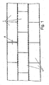
- a bottom is formed by a plurality of adjacently arranged plates 1, each at opposite longitudinal edges and opposite end edges are connected.
- the plates arranged at the edge can either be surrounded by a frame towards the outside or have a corresponding termination, since there no connection to an adjacent plate has to be made.
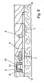
- connection system at the longitudinal edges is in the FIGS. 2 to 4 shown in section.
- a metal, in particular aluminum existing groove piece 2 is arranged, which engages with a web 21 in the plate 1 and is glued there.
- this groove piece engages in the opposite plate 1 made of metal, in particular aluminum, existing spring piece 3, wherein the spring piece 3 engages with a web 31 in the plate 1 and is glued there.
- the plates 1 lie next to one another in a horizontal plane and form a surface.
- the connection system is not visible from the outside and the spring piece 3 engages in the groove piece 2 a.
- the groove piece 2 has, in addition to the web 21, a groove 22 adjoining it, the opening of which narrows from its closed side to the open side. At the bottom of the groove, a tongue 23 connects, which has a rounded trough 24.
- the spring piece has, in addition to the above-mentioned web 31, a spring 32 running obliquely upward away from the web 31, which engages behind the groove 22 narrowing from its closed side toward the open side. At the rear lower side of the spring 32, a bulge 34 is formed, which engages with the trough 24 of the Nut Publisheds 2 form-fitting manner.
- groove 2 and spring piece 3 Due to the geometry of groove 2 and spring piece 3, the groove 2 and spring piece 3 are separable from each other in a very favorable for the construction and dismantling angle range of 5 ° to 25 ° and yet provide in the assembled state a secure cohesion against pulling in horizontal direction. In a special embodiment, these are even in an angular range of 10 ° to 20 ° separable from each other.
- the longitudinal edges of the plates 1 are supported in a face-side notching of the plates by a relining of the plate surface material with the groove piece 2 and the spring piece 3. As a result, in particular the corner regions of the plates are protected against breakage. From the rear region of the spring, a rail 33 protrudes upward, which forms a stable stop together with an end edge of an upper groove leg.
- the webs of tongue and groove are provided with grooves 25, 35 to ensure a uniform distribution of an adhesive along the webs.
- FIG. 5 the connection of two end edges of adjacent plates 1 is shown.
- an existing metal web 4 is fixed, which protrudes beyond the front edge of the plate 1.
- an upward-facing mandrel 5 having a frusto-conical portion 51 is formed in the upper portion thereof.
- the mandrel 5 is arranged in a receptacle 6, which is formed from a hood-shaped plastic part, which is enclosed by means of teeth in the material of the plate.
- the receptacle is covered by a cover layer 61. The formation of a gap between the end edges of adjacent plates is prevented by the positive retention of the dome 5 in the receptacle 6.
- a spring 7 which is inserted in equal shares in a groove on the end edges of the adjacent plates 1 and extends substantially over the entire length of the end edges, prevents rotation of the plates 1 in the region of the end edges.
- the strip-shaped spring 7 is tapered wedge-shaped towards the end, so that it is clamped in the groove can be fixed, which may be at least partially also wedge-shaped.
- the web 4 is positioned on the opposite plate with a centering pin 8 and screwed via schematically illustrated screw 9 with the plate 1. The centering pin 8 is held in a bore in the plate 1.
- FIG. 6 is a slightly modified embodiment of a connection system with a strip-shaped groove piece 2 'and spring piece 3' shown.
- the groove piece 2 ' comprises a lower, longer leg 27 and an upper, shorter leg 26, which has a chamfer 29 at the bottom end.
- a cavity 30 is formed, which simplifies the mounting and dismounting of the connection system.
- the plates 1 are glued on their underside with a layer of foam 10, which may be covered on the bottom side with a nonwoven material.
- a layer of foam 10 which may be covered on the bottom side with a nonwoven material.
- the foam may also be provided a foamed plastic, if a lower elasticity is desired.
- the plates 1 can be laid on a hard surface and still have the necessary for sporting events elasticity.
Landscapes
- Engineering & Computer Science (AREA)
- Architecture (AREA)
- Civil Engineering (AREA)
- Structural Engineering (AREA)
- Floor Finish (AREA)
- Joining Of Building Structures In Genera (AREA)
Claims (10)
- Système de liaison destiné à un plancher mobile comprenant plusieurs plaques (1) de forme rectangulaire en vue de dessus qui peuvent respectivement être reliées sur leurs faces de chant longitudinales avec des plaques (1) voisines, les plaques (1) formant une surface commune, et, pour permettre la liaison de deux plaques (1) voisines en direction longitudinale sont respectivement prévus un élément à rainure (2) et un élément élastique (3) dans les faces de chant longitudinales des plaques (1) voisines, l'élément à rainure (2) et l'élément élastique (3) étant réalisés en un matériau ayant une forme stable, l'élément à rainure (2) comprenant une barrette (21) entourée par le matériau de la plaque, une rainure (22) se raccordant à celle-ci, dont l'ouverture diminue de sa face fermée à sa face ouverte, et une languette (23) se raccordant au bord inférieur de la rainure, et l'élément élastique (3) comprenant une barrette (31) entourée par le matériau de la plaque et un tronçon élastique (32) s'étendant obliquement vers le haut en s'éloignant de la barrette, caractérisé en ce que
la languette (23) de l'élément à rainure (2) comporte une cavité en forme de cuvette (24), tandis que l'élément élastique (3) comporte un bossage (34) sur sa face inférieure, cette cavité et ce bossage venant en prise par une liaison par la forme. - Système de liaison conforme à la revendication 1,
caractérisé en ce que
la barrette (21) de l'élément à rainure (2) et/ou la barrette (31) de l'élément élastique (3) sont collées dans les faces de chant longitudinales des plaques (1). - Système de liaison conforme à la revendication 1 ou 2,
caractérisé en ce que
des stries (25, 35) sont prévues dans la barrette (21) de l'élément à rainure (2) et/ou dans la nervure (31) de l'élément élastique (3). - Système de liaison conforme à l'une des revendications précédentes,
caractérisé en ce que
l'élément à rainure (2) et/ou l'élément élastique (3) est(sont) réalisé(s) en métal. - Système de liaison conforme à l'une des revendications précédentes,
caractérisé en ce que
la face de chant frontale de la branche supérieure (26) de la rainure forme une butée avec la face de chant d'un rail (33) de l'élément élastique (3). - Système de liaison conforme à l'une des revendications précédentes,
caractérisé en ce que
l'élément à rainure (2) et l'élément élastique (3) peuvent être séparés l'un de l'autre sous un angle de 5° à 25°. - Système de liaison conforme à l'une des revendications précédentes,
caractérisé en ce que
l'élément à rainure (2) et l'élément élastique (3) peuvent être séparés l'un de l'autre sous un angle de 10° à 20°. - Système de liaison conforme à l'une des revendications précédentes,
caractérisé en ce que
les faces de chant longitudinales des plaques (1) sont soutenues, lors d'un décrochage frontal des plaques, par soutien du matériau de la surface des plaques avec l'élément à rainure (2) ou l'élément élastique (3). - Système de liaison conforme à l'une des revendications précédentes,
caractérisé en ce que
lorsque l'élément à rainure (2) et l'élément élastique (3) sont assemblés la face supérieure du tronçon élastique (32) s'applique contre la branche supérieure de la rainure (26), et, entre la branche inférieure (27) de la rainure et le tronçon élastique (32) est formé un volume creux (28) qui se ferme vers la cavité (24). - Système de liaison conforme à une des revendications précédentes,
caractérisé en ce que
les faces frontales de plaques voisines peuvent être reliées entre elles par une barrette (4) fixée à la première plaque et dépassant de celle-ci, et sur la partie en saillie de laquelle dépasse vers haut un goujon (5) qui vient en prise dans une cavité (6) de la plaque voisine.
Applications Claiming Priority (2)
| Application Number | Priority Date | Filing Date | Title |
|---|---|---|---|
| DE202006006888U DE202006006888U1 (de) | 2006-04-26 | 2006-04-26 | Verbindungssystem für einen mobilen Boden |
| PCT/EP2007/052471 WO2007124980A1 (fr) | 2006-04-26 | 2007-03-15 | Systeme de connexion pour un fond mobile |
Publications (2)
| Publication Number | Publication Date |
|---|---|
| EP2010733A1 EP2010733A1 (fr) | 2009-01-07 |
| EP2010733B1 true EP2010733B1 (fr) | 2014-09-03 |
Family
ID=36710300
Family Applications (1)
| Application Number | Title | Priority Date | Filing Date |
|---|---|---|---|
| EP07726958.7A Active EP2010733B1 (fr) | 2006-04-26 | 2007-03-15 | Systeme de connexion pour un fond mobile |
Country Status (5)
| Country | Link |
|---|---|
| EP (1) | EP2010733B1 (fr) |
| DE (2) | DE202006006888U1 (fr) |
| ES (1) | ES2525417T3 (fr) |
| PT (1) | PT2010733E (fr) |
| WO (1) | WO2007124980A1 (fr) |
Cited By (1)
| Publication number | Priority date | Publication date | Assignee | Title |
|---|---|---|---|---|
| DE202023107141U1 (de) * | 2023-12-01 | 2025-03-06 | Holz-Speckmann Gmbh & Co. Kg | Mobiler Boden |
Families Citing this family (7)
| Publication number | Priority date | Publication date | Assignee | Title |
|---|---|---|---|---|
| EP2118373B1 (fr) | 2007-03-15 | 2013-05-08 | Holz-Speckmann GmbH | Plaque de sol |
| DE102007013189A1 (de) | 2007-03-15 | 2008-09-18 | Holz-Speckmann Gmbh | Bodenplatte |
| FR2921086B1 (fr) * | 2007-09-18 | 2010-04-09 | Gesport | Panneau pour la fabrication d'un plancher, et plancher ainsi obtenu |
| EP2221431B1 (fr) * | 2009-01-16 | 2014-06-04 | Flooring Technologies Ltd. | Dispositif de raccordement de panneaux de sol |
| DE202009002023U1 (de) | 2009-04-01 | 2009-07-02 | Becker Sport- Und Freizeitanlagen Gmbh | Sportbodensegment |
| WO2016038228A1 (fr) * | 2014-09-10 | 2016-03-17 | Alonso Alonso José Ángel | Panneau pour sols démontables haute résistance |
| PT108736B (pt) | 2015-07-29 | 2022-05-04 | Nuno Miguel Simoes Vicente | Sistema para ligação e método de encaixe entre si de módulos para revestimento de pavimentos |
Family Cites Families (7)
| Publication number | Priority date | Publication date | Assignee | Title |
|---|---|---|---|---|
| SE0002342L (sv) * | 2000-06-22 | 2001-07-16 | Tarkett Sommer Ab | Golvbräda med kopplingsorgan |
| DE3343601C2 (de) * | 1983-12-02 | 1987-02-12 | Bütec Gesellschaft für bühnentechnische Einrichtungen mbH, 4010 Hilden | Entfernbarer Bodenbelag |
| GB9624901D0 (en) * | 1995-12-05 | 1997-01-15 | Sico Inc | Portable floor |
| BE1010487A6 (nl) | 1996-06-11 | 1998-10-06 | Unilin Beheer Bv | Vloerbekleding bestaande uit harde vloerpanelen en werkwijze voor het vervaardigen van dergelijke vloerpanelen. |
| BE1014256A6 (nl) * | 2001-06-21 | 2003-07-01 | Geuens Fran Ois | Zwevende plaatsing van een massieve houten plankenvloer. |
| DE20307074U1 (de) * | 2003-05-06 | 2004-09-16 | Holz-Speckmann Gmbh | Verbindungssystem für einen mobilen Boden |
| DE20318892U1 (de) * | 2003-12-05 | 2004-03-04 | Akzenta Paneele + Profile Gmbh | Verriegelungssystem für Paneele |
-
2006
- 2006-04-26 DE DE202006006888U patent/DE202006006888U1/de not_active Expired - Lifetime
-
2007
- 2007-03-15 DE DE102007013188A patent/DE102007013188A1/de not_active Withdrawn
- 2007-03-15 ES ES07726958.7T patent/ES2525417T3/es active Active
- 2007-03-15 PT PT77269587T patent/PT2010733E/pt unknown
- 2007-03-15 WO PCT/EP2007/052471 patent/WO2007124980A1/fr not_active Ceased
- 2007-03-15 EP EP07726958.7A patent/EP2010733B1/fr active Active
Cited By (1)
| Publication number | Priority date | Publication date | Assignee | Title |
|---|---|---|---|---|
| DE202023107141U1 (de) * | 2023-12-01 | 2025-03-06 | Holz-Speckmann Gmbh & Co. Kg | Mobiler Boden |
Also Published As
| Publication number | Publication date |
|---|---|
| EP2010733A1 (fr) | 2009-01-07 |
| DE202006006888U1 (de) | 2006-07-06 |
| DE102007013188A1 (de) | 2007-11-08 |
| PT2010733E (pt) | 2014-12-02 |
| WO2007124980A1 (fr) | 2007-11-08 |
| ES2525417T3 (es) | 2014-12-22 |
Similar Documents
| Publication | Publication Date | Title |
|---|---|---|
| EP2010733B1 (fr) | Systeme de connexion pour un fond mobile | |
| EP1294995B1 (fr) | Système de plancher comprenant un pluralité de planches de plancher identiques | |
| EP2208835B1 (fr) | Panneau, en particulier panneau de sol | |
| EP1223265A2 (fr) | Panneau de parquet | |
| DE102007017087A1 (de) | Paneel, insbesondere Bodenpaneel | |
| DE102007026342A1 (de) | Set aus tafelförmigen Paneelen mit bewegbarem Verriegelungselement | |
| DE2007129A1 (de) | Estrichplatte mit einem Überzug | |
| EP1961889B1 (fr) | Assemblage de fixation avec un profilé de fixation et un crochet de fixation | |
| DE9320652U1 (de) | Rahmenelement und Einsatzelement für Ställe | |
| DE1811932A1 (de) | Betonbalken,insbesondere fuer Raumgitter und Stuetzmauern | |
| DE102014106068B4 (de) | Vorrichtung zur Verbindung zweier einander gegenüberliegender plattenförmiger Schalungselemente | |
| DE102008053230B4 (de) | Einrichtung zum Verbinden von Bauplatten, insbesondere Bodenpaneelen | |
| DE3888846T2 (de) | Verbindung zwischen zwei Sandwichtafeln und Modulbausystem mit dieser Verbindung. | |
| EP2327846A2 (fr) | Plaque de fond en matière synthétique | |
| WO2009006926A1 (fr) | CONCEPT DE PANNEAU DE PAROI À 45º | |
| DE202024104862U1 (de) | Entwässerungsrinne zum Ableiten von Oberflächenwasser | |
| DE19514165A1 (de) | Bauelement sowie damit hergestellte Wandverkleidung | |
| EP4174249A1 (fr) | Panneau creux composite et ensemble comprenant un certain nombre de panneaux creux composites | |
| DE19640128A1 (de) | Bodenbelag-Element | |
| DE102020118689A1 (de) | Bauelementsystem | |
| EP0365834B1 (fr) | Connection d'angle rigide d'une poutre en bois avec un pilier | |
| DE4412622A1 (de) | Bodenbelag | |
| DE102020123896B4 (de) | Wandverkleidung, Gebäudewand und Behälter | |
| DE102007063837B3 (de) | Set aus tafelförmigen Paneelen mit bewegbarem Verriegelungselement | |
| DE9212668U1 (de) | Lärmschutzwand |
Legal Events
| Date | Code | Title | Description |
|---|---|---|---|
| PUAI | Public reference made under article 153(3) epc to a published international application that has entered the european phase |
Free format text: ORIGINAL CODE: 0009012 |
|
| 17P | Request for examination filed |
Effective date: 20080805 |
|
| AK | Designated contracting states |
Kind code of ref document: A1 Designated state(s): AT BE BG CH CY CZ DE DK EE ES FI FR GB GR HU IE IS IT LI LT LU LV MC MT NL PL PT RO SE SI SK TR |
|
| AX | Request for extension of the european patent |
Extension state: AL BA HR MK RS |
|
| DAX | Request for extension of the european patent (deleted) | ||
| TPAC | Observations filed by third parties |
Free format text: ORIGINAL CODE: EPIDOSNTIPA |
|
| GRAP | Despatch of communication of intention to grant a patent |
Free format text: ORIGINAL CODE: EPIDOSNIGR1 |
|
| INTG | Intention to grant announced |
Effective date: 20140410 |
|
| GRAS | Grant fee paid |
Free format text: ORIGINAL CODE: EPIDOSNIGR3 |
|
| GRAA | (expected) grant |
Free format text: ORIGINAL CODE: 0009210 |
|
| AK | Designated contracting states |
Kind code of ref document: B1 Designated state(s): AT BE BG CH CY CZ DE DK EE ES FI FR GB GR HU IE IS IT LI LT LU LV MC MT NL PL PT RO SE SI SK TR |
|
| REG | Reference to a national code |
Ref country code: GB Ref legal event code: FG4D Free format text: NOT ENGLISH |
|
| REG | Reference to a national code |
Ref country code: AT Ref legal event code: REF Ref document number: 685717 Country of ref document: AT Kind code of ref document: T Effective date: 20140915 Ref country code: CH Ref legal event code: EP |
|
| REG | Reference to a national code |
Ref country code: IE Ref legal event code: FG4D Free format text: LANGUAGE OF EP DOCUMENT: GERMAN |
|
| REG | Reference to a national code |
Ref country code: DE Ref legal event code: R096 Ref document number: 502007013412 Country of ref document: DE Effective date: 20141009 |
|
| REG | Reference to a national code |
Ref country code: CH Ref legal event code: NV Representative=s name: ISLER AND PEDRAZZINI AG, CH |
|
| REG | Reference to a national code |
Ref country code: PT Ref legal event code: SC4A Free format text: AVAILABILITY OF NATIONAL TRANSLATION Effective date: 20141119 |
|
| REG | Reference to a national code |
Ref country code: ES Ref legal event code: FG2A Ref document number: 2525417 Country of ref document: ES Kind code of ref document: T3 Effective date: 20141222 |
|
| PG25 | Lapsed in a contracting state [announced via postgrant information from national office to epo] |
Ref country code: GR Free format text: LAPSE BECAUSE OF FAILURE TO SUBMIT A TRANSLATION OF THE DESCRIPTION OR TO PAY THE FEE WITHIN THE PRESCRIBED TIME-LIMIT Effective date: 20141204 Ref country code: LT Free format text: LAPSE BECAUSE OF FAILURE TO SUBMIT A TRANSLATION OF THE DESCRIPTION OR TO PAY THE FEE WITHIN THE PRESCRIBED TIME-LIMIT Effective date: 20140903 Ref country code: FI Free format text: LAPSE BECAUSE OF FAILURE TO SUBMIT A TRANSLATION OF THE DESCRIPTION OR TO PAY THE FEE WITHIN THE PRESCRIBED TIME-LIMIT Effective date: 20140903 Ref country code: SE Free format text: LAPSE BECAUSE OF FAILURE TO SUBMIT A TRANSLATION OF THE DESCRIPTION OR TO PAY THE FEE WITHIN THE PRESCRIBED TIME-LIMIT Effective date: 20140903 |
|
| REG | Reference to a national code |
Ref country code: NL Ref legal event code: VDEP Effective date: 20140903 |
|
| REG | Reference to a national code |
Ref country code: LT Ref legal event code: MG4D |
|
| PG25 | Lapsed in a contracting state [announced via postgrant information from national office to epo] |
Ref country code: CY Free format text: LAPSE BECAUSE OF FAILURE TO SUBMIT A TRANSLATION OF THE DESCRIPTION OR TO PAY THE FEE WITHIN THE PRESCRIBED TIME-LIMIT Effective date: 20140903 Ref country code: LV Free format text: LAPSE BECAUSE OF FAILURE TO SUBMIT A TRANSLATION OF THE DESCRIPTION OR TO PAY THE FEE WITHIN THE PRESCRIBED TIME-LIMIT Effective date: 20140903 |
|
| PG25 | Lapsed in a contracting state [announced via postgrant information from national office to epo] |
Ref country code: NL Free format text: LAPSE BECAUSE OF FAILURE TO SUBMIT A TRANSLATION OF THE DESCRIPTION OR TO PAY THE FEE WITHIN THE PRESCRIBED TIME-LIMIT Effective date: 20140903 |
|
| PG25 | Lapsed in a contracting state [announced via postgrant information from national office to epo] |
Ref country code: EE Free format text: LAPSE BECAUSE OF FAILURE TO SUBMIT A TRANSLATION OF THE DESCRIPTION OR TO PAY THE FEE WITHIN THE PRESCRIBED TIME-LIMIT Effective date: 20140903 Ref country code: SK Free format text: LAPSE BECAUSE OF FAILURE TO SUBMIT A TRANSLATION OF THE DESCRIPTION OR TO PAY THE FEE WITHIN THE PRESCRIBED TIME-LIMIT Effective date: 20140903 Ref country code: IS Free format text: LAPSE BECAUSE OF FAILURE TO SUBMIT A TRANSLATION OF THE DESCRIPTION OR TO PAY THE FEE WITHIN THE PRESCRIBED TIME-LIMIT Effective date: 20150103 Ref country code: CZ Free format text: LAPSE BECAUSE OF FAILURE TO SUBMIT A TRANSLATION OF THE DESCRIPTION OR TO PAY THE FEE WITHIN THE PRESCRIBED TIME-LIMIT Effective date: 20140903 Ref country code: RO Free format text: LAPSE BECAUSE OF FAILURE TO SUBMIT A TRANSLATION OF THE DESCRIPTION OR TO PAY THE FEE WITHIN THE PRESCRIBED TIME-LIMIT Effective date: 20140903 |
|
| PG25 | Lapsed in a contracting state [announced via postgrant information from national office to epo] |
Ref country code: PL Free format text: LAPSE BECAUSE OF FAILURE TO SUBMIT A TRANSLATION OF THE DESCRIPTION OR TO PAY THE FEE WITHIN THE PRESCRIBED TIME-LIMIT Effective date: 20140903 |
|
| REG | Reference to a national code |
Ref country code: DE Ref legal event code: R097 Ref document number: 502007013412 Country of ref document: DE |
|
| PLBE | No opposition filed within time limit |
Free format text: ORIGINAL CODE: 0009261 |
|
| STAA | Information on the status of an ep patent application or granted ep patent |
Free format text: STATUS: NO OPPOSITION FILED WITHIN TIME LIMIT |
|
| PG25 | Lapsed in a contracting state [announced via postgrant information from national office to epo] |
Ref country code: DK Free format text: LAPSE BECAUSE OF FAILURE TO SUBMIT A TRANSLATION OF THE DESCRIPTION OR TO PAY THE FEE WITHIN THE PRESCRIBED TIME-LIMIT Effective date: 20140903 |
|
| 26N | No opposition filed |
Effective date: 20150604 |
|
| PG25 | Lapsed in a contracting state [announced via postgrant information from national office to epo] |
Ref country code: LU Free format text: LAPSE BECAUSE OF FAILURE TO SUBMIT A TRANSLATION OF THE DESCRIPTION OR TO PAY THE FEE WITHIN THE PRESCRIBED TIME-LIMIT Effective date: 20150315 Ref country code: MC Free format text: LAPSE BECAUSE OF FAILURE TO SUBMIT A TRANSLATION OF THE DESCRIPTION OR TO PAY THE FEE WITHIN THE PRESCRIBED TIME-LIMIT Effective date: 20140903 |
|
| GBPC | Gb: european patent ceased through non-payment of renewal fee |
Effective date: 20150315 |
|
| PG25 | Lapsed in a contracting state [announced via postgrant information from national office to epo] |
Ref country code: SI Free format text: LAPSE BECAUSE OF FAILURE TO SUBMIT A TRANSLATION OF THE DESCRIPTION OR TO PAY THE FEE WITHIN THE PRESCRIBED TIME-LIMIT Effective date: 20140903 |
|
| REG | Reference to a national code |
Ref country code: IE Ref legal event code: MM4A |
|
| PG25 | Lapsed in a contracting state [announced via postgrant information from national office to epo] |
Ref country code: GB Free format text: LAPSE BECAUSE OF NON-PAYMENT OF DUE FEES Effective date: 20150315 Ref country code: IE Free format text: LAPSE BECAUSE OF NON-PAYMENT OF DUE FEES Effective date: 20150315 |
|
| REG | Reference to a national code |
Ref country code: FR Ref legal event code: PLFP Year of fee payment: 10 |
|
| REG | Reference to a national code |
Ref country code: AT Ref legal event code: MM01 Ref document number: 685717 Country of ref document: AT Kind code of ref document: T Effective date: 20150315 |
|
| PG25 | Lapsed in a contracting state [announced via postgrant information from national office to epo] |
Ref country code: AT Free format text: LAPSE BECAUSE OF NON-PAYMENT OF DUE FEES Effective date: 20150315 |
|
| PG25 | Lapsed in a contracting state [announced via postgrant information from national office to epo] |
Ref country code: MT Free format text: LAPSE BECAUSE OF FAILURE TO SUBMIT A TRANSLATION OF THE DESCRIPTION OR TO PAY THE FEE WITHIN THE PRESCRIBED TIME-LIMIT Effective date: 20140903 |
|
| REG | Reference to a national code |
Ref country code: FR Ref legal event code: PLFP Year of fee payment: 11 |
|
| PG25 | Lapsed in a contracting state [announced via postgrant information from national office to epo] |
Ref country code: BG Free format text: LAPSE BECAUSE OF FAILURE TO SUBMIT A TRANSLATION OF THE DESCRIPTION OR TO PAY THE FEE WITHIN THE PRESCRIBED TIME-LIMIT Effective date: 20140903 Ref country code: HU Free format text: LAPSE BECAUSE OF FAILURE TO SUBMIT A TRANSLATION OF THE DESCRIPTION OR TO PAY THE FEE WITHIN THE PRESCRIBED TIME-LIMIT; INVALID AB INITIO Effective date: 20070315 |
|
| PG25 | Lapsed in a contracting state [announced via postgrant information from national office to epo] |
Ref country code: BE Free format text: LAPSE BECAUSE OF NON-PAYMENT OF DUE FEES Effective date: 20150331 |
|
| REG | Reference to a national code |
Ref country code: FR Ref legal event code: PLFP Year of fee payment: 12 |
|
| PGFP | Annual fee paid to national office [announced via postgrant information from national office to epo] |
Ref country code: PT Payment date: 20250313 Year of fee payment: 19 |
|
| PGFP | Annual fee paid to national office [announced via postgrant information from national office to epo] |
Ref country code: FR Payment date: 20250306 Year of fee payment: 19 |
|
| PGFP | Annual fee paid to national office [announced via postgrant information from national office to epo] |
Ref country code: TR Payment date: 20250307 Year of fee payment: 19 |
|
| PGFP | Annual fee paid to national office [announced via postgrant information from national office to epo] |
Ref country code: ES Payment date: 20250416 Year of fee payment: 19 |
|
| PGFP | Annual fee paid to national office [announced via postgrant information from national office to epo] |
Ref country code: IT Payment date: 20250331 Year of fee payment: 19 |
|
| PGFP | Annual fee paid to national office [announced via postgrant information from national office to epo] |
Ref country code: CH Payment date: 20250401 Year of fee payment: 19 |
|
| PGFP | Annual fee paid to national office [announced via postgrant information from national office to epo] |
Ref country code: DE Payment date: 20260116 Year of fee payment: 20 |