EP2010886B1 - Vorrichtung zur entnahme unter druck stehender proben - Google Patents
Vorrichtung zur entnahme unter druck stehender proben Download PDFInfo
- Publication number
- EP2010886B1 EP2010886B1 EP07731291A EP07731291A EP2010886B1 EP 2010886 B1 EP2010886 B1 EP 2010886B1 EP 07731291 A EP07731291 A EP 07731291A EP 07731291 A EP07731291 A EP 07731291A EP 2010886 B1 EP2010886 B1 EP 2010886B1
- Authority
- EP
- European Patent Office
- Prior art keywords
- cylinder
- piston
- enclosure
- sample
- housing
- Prior art date
- Legal status (The legal status is an assumption and is not a legal conclusion. Google has not performed a legal analysis and makes no representation as to the accuracy of the status listed.)
- Active
Links
Images


Classifications
-
- G—PHYSICS
- G01—MEASURING; TESTING
- G01N—INVESTIGATING OR ANALYSING MATERIALS BY DETERMINING THEIR CHEMICAL OR PHYSICAL PROPERTIES
- G01N1/00—Sampling; Preparing specimens for investigation
- G01N1/02—Devices for withdrawing samples
- G01N1/10—Devices for withdrawing samples in the liquid or fluent state
- G01N1/12—Dippers; Dredgers
-
- G—PHYSICS
- G01—MEASURING; TESTING
- G01N—INVESTIGATING OR ANALYSING MATERIALS BY DETERMINING THEIR CHEMICAL OR PHYSICAL PROPERTIES
- G01N1/00—Sampling; Preparing specimens for investigation
- G01N1/02—Devices for withdrawing samples
- G01N1/10—Devices for withdrawing samples in the liquid or fluent state
- G01N2001/1031—Sampling from special places
-
- G—PHYSICS
- G01—MEASURING; TESTING
- G01N—INVESTIGATING OR ANALYSING MATERIALS BY DETERMINING THEIR CHEMICAL OR PHYSICAL PROPERTIES
- G01N1/00—Sampling; Preparing specimens for investigation
- G01N1/02—Devices for withdrawing samples
- G01N1/10—Devices for withdrawing samples in the liquid or fluent state
- G01N1/14—Suction devices, e.g. pumps; Ejector devices
- G01N2001/1445—Overpressure, pressurisation at sampling point
- G01N2001/1454—Positive displacement, piston
-
- G—PHYSICS
- G01—MEASURING; TESTING
- G01N—INVESTIGATING OR ANALYSING MATERIALS BY DETERMINING THEIR CHEMICAL OR PHYSICAL PROPERTIES
- G01N1/00—Sampling; Preparing specimens for investigation
- G01N1/02—Devices for withdrawing samples
- G01N1/10—Devices for withdrawing samples in the liquid or fluent state
- G01N1/20—Devices for withdrawing samples in the liquid or fluent state for flowing or falling materials
- G01N1/2035—Devices for withdrawing samples in the liquid or fluent state for flowing or falling materials by deviating part of a fluid stream, e.g. by drawing-off or tapping
- G01N2001/205—Devices for withdrawing samples in the liquid or fluent state for flowing or falling materials by deviating part of a fluid stream, e.g. by drawing-off or tapping using a valve
- G01N2001/2057—Sample chamber in a valve/piston
Definitions
- the present invention relates to a device for sampling under pressure comprising a sampling chamber, and a system for opening the sampling chamber of such a device for the recovery of samples under pressure.
- the invention relates more particularly to a device for sampling subsea samples under pressure, gases, and / or liquids and / or solids such as gas hydrates.
- the precharge gas being at a pressure lower than the pressure hydrostatic, the opening of a valve of an intake circuit, the fluid to be taken enters the sampling chamber, the piston of the latter pushes the damping fluid in the lower chamber, causing a movement of the piston from this last down.
- Sample aspiration is interrupted when the pressure of the precharge gas reaches the pressure of the sample.
- the preparation of the cell preceding its use, as well as the recovery of the sample from the cell, are long and tedious.
- the configuration is related to the operating pressure.
- the sample is taken by suction via the intake circuit.
- Some types of samples may be altered by rapid aspiration and / or closure of the intake system and interruption of sampling. This is particularly the case for gas hydrates: the suction of gas saturated fluids, methane for example causes, under certain conditions of temperature and pressure the formation of gas hydrates.
- Such sampling devices prove to be unsuitable for taking such samples.
- Other documents, such as DE 3310032 and US 3266323 describe sampling devices of the state of the art.
- the document GB 2278830 describes a system for opening a pressure sampling chamber.
- the object of the present invention is to provide a sampling device overcoming the aforementioned drawbacks, allowing the sampling of samples consisting of gases, liquids and / or solids without imposing any movement on the sample, in particular without suction and without mixture of the initial volume.
- the sampling device comprises a sampling chamber and a separate displacement system to which the elements of the chamber can be assembled, comprising a jack which uses the hydrostatic pressure to bring the chamber into the closed position.
- the device according to the invention allows sample collection under pressure, underwater environment, nuclear or any other hostile environment, without imposing any movement on the sample, in particular without aspiration, and without mixing the initial volume, sample being trapped in the liner, between the two plugs, during the relative movement of the axis relative to the liner.
- the device according to the invention is simple in design, reliable, compact and robust and can be implemented easily, safely.
- the sampling chamber is particularly simple in design, compact and easy to handle after sampling for the recovery of the sample. The device does not require adjustment according to the depth of use.
- the device operates from a minimum depth chosen at the time of design, primarily depending on the diameter of the cylinder. Above this minimum depth, the limit is related to the mechanical strength of the cell and cylinder in particular.
- the separable character of the cylinder and the enclosure makes it possible to use the same cylinder for taking several successive samples in several enclosures. Moreover, the same enclosure can be used with different cylinders, dimensioned for sampling at different minimum depths and / or at different speeds and / or closing forces.
- said communication means comprise a retractable pin, mounted in the cylinder and held by elastic return means, such as a single spring, in a closed position of an intake circuit connecting the inside the cylinder in the middle outside.
- Said pin is movable under the effect of an external pressure exerted on said pin against the biasing means, in an open position of said intake circuit for admission of seawater into the cylinder. Sampling of the sample is carried out simply by placing the cylinder in communication with the outside.
- the actuation of the pin to trigger the closure of the enclosure can be easily performed by a remote underwater vehicle.
- the low effort required to actuate the pin is compatible with automation of the closure, for example by means of a solenoid-type system.
- the enclosure is closed by moving the liner relative to the fixed fixed axis, the piston rod is able to slide in a sealed manner in the second end of the cylinder opposite to the first end of the housing.
- cylinder which carries the means of communication with the external medium), the free end of said rod being adapted to be assembled at a first end of the liner, the axis being adapted to be assembled by a first cap to the cylinder by said connecting means.
- the liner comprises, at a first end, two longitudinal lugs for its assembly to the jack, the axis comprising a first plug provided with an axial thread for its assembly to the jack.
- the displacement system is able to bring the sampling chamber into a closed position in which the second plug is partially engaged in the sleeve, the outer portion having an annular groove for the implementation of an O-ring for the subsequent opening of the enclosure by means of an opening system suitable for the recovery of the sample under pressure.
- said connecting means comprise a hollow connecting rod assembled to the second end of the cylinder, in which the piston rod slides, the axis being assembled by its first plug to the free threaded end of the rod. connection, the liner being assembled by its longitudinal ears at the free end of the piston rod by means of a pin adapted to slide in two longitudinal slots of the hollow rod during the displacement of the piston rod, the closure of the enclosure being then obtained by moving down the liner when moving the piston from an activated high position to a deactivated low position.
- the cylinder and the piston of the jack are each equipped with a discharge valve allowing a passage of fluid from the inside of the cylinder to the outside without displacement of the piston when the pressure in the cylinder is greater than that of the environment, thus allowing safe handling of the cylinder after recovery to the surface.
- the device further comprises a cone, preferably transparent, capable of being removably assembled on the jacket of the sampling chamber for the trapping of hydrocarbon-type fluids and / or lighter gases than the water, the device then allowing to keep under pressure an intact and unmixed sample volume resulting from a collection by said cone vertical upward seeps.
- a cone preferably transparent, capable of being removably assembled on the jacket of the sampling chamber for the trapping of hydrocarbon-type fluids and / or lighter gases than the water, the device then allowing to keep under pressure an intact and unmixed sample volume resulting from a collection by said cone vertical upward seeps.
- the device further comprises a frame integral with the cylinder surrounding the sampling chamber assembled to said jack to protect the latter from shocks, whereby the device is able to rest on the ground.
- the sampling chamber comprises locking means of the enclosure in the open position, said locking means comprising for example a screw adapted to be screwed into a tapping of the jacket and to engage in an annular groove of the first plug of the axle.
- the shoulder of the housing has a first radial groove opening on the recovery channel, sealing means being provided to ensure the seal between the plug placed in the housing and the wall of the lower part of the housing, in order to reduce the efforts taken by the opening system and to minimize the volume placed in communication with the interior of the enclosure and consequently the expansion of the sample.
- said cap comprises a first O-ring ensuring the seal between the liner and the cap and a second O-ring sealing between the cap and the lower part of the housing, the latter being preferably arranged at the bottom of the housing. outside the jacket in the closed position of the enclosure.
- the block is equipped with a pressure sensor opening on a second radial groove for measuring the pressure of the sample after opening the chamber and before opening the recovery circuit.
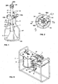
- the sampling device according to the invention illustrated in Figures 1 to 5 intended in particular for submarine sample collection, such as gas hydrates, comprises a sampling chamber 1 removably assembled to a jack 2 which uses the hydrostatic pressure to close the sampling chamber and trap the sample.
- the enclosure 1 consists of a jacket 11, formed of a cylindrical tube, and an axis 12 formed of an axial rod 121 provided at its ends with two cylinders forming a first tape or plug, said upper plug 122 , and a second tape or plug, said lower plug.
- the plugs are able to slide tightly in the jacket, to form a sealed sampling chamber 13 between the tubular wall of the jacket and the two plugs in the closed position of the chamber illustrated in FIGS. figures 3 and 5 .
- Each plug has an annular groove in which is mounted an O-ring 124, 125 to seal between the plugs and the sleeve in the closed position of the enclosure.
- the axis is advantageously monobloc.
- the upper plug 122 has an axial thread 126 for its assembly to the threaded end of a hollow connecting rod mounted fixed relative to the cylinder of the cylinder, as described below.
- the liner comprises at a first end, said upper 111, two diametrically opposed longitudinal lugs 112, each provided with a bore for its assembly to the piston rod of the jack.
- the upper cap further comprises an annular groove 127 for receiving the end of a screw 14 screwed into a transverse tapping of the jacket to lock the enclosure in the closed position. In this closed position, the plug 123 is partially engaged in the liner, so as to maintain apparent an outer portion equipped with an O-ring 128 which will be used for the recovery of the sample as described below.
- a cone 3 is mounted on the second end of the liner, said lower 113, for trapping gases.
- An O-ring 114 mounted in an annular groove of the liner, seals between the liner and the cone.
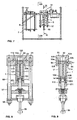
- the jack 2 comprises a cylinder 21 in which is slidably mounted a piston 22 equipped with a rod 23.
- the cylinder is formed of a hollow tube provided with an upper flange 211 and a lower flange 212.
- the cylinder is closed in a sealed manner by an upper plug 24 fixed to its upper flange by means of nuts and screws, and by a lower ring 25 with flange, fitted into the cylinder and assembled by its flange 251 to the lower flange 212 of the cylinder, the piston rod being able to slide sealingly through said ring.
- the ring 25 is equipped with an O-ring 252 to seal between the cylinder and said ring.
- a hollow connecting rod 26 is axially connected to the lower end of the cylinder.
- the hollow rod has an upper flange 261 fixed to the lower flange 212 of the cylinder, by means of screws and nuts, by interposing between the two flange 251 of the ring.
- the connecting rod has a threaded free end 262 for its assembly to the top cap 122 of the enclosure.
- the free end 231 of the piston rod is arranged axially in the hollow connecting rod and is provided with a transverse piercing opening enabling it to be connected to the lugs 112 of the liner by means of a pin 27 passing through diametrically opposite longitudinal openings of the hollow rod, as illustrated in FIGS. figures 2 and 3 .
- the upper plug 24 of the jack comprises an intake circuit 28 connecting the external medium to the inside of the cylinder.
- the intake circuit is formed of a vertical channel 281 opening into the cylinder and equipped at the outlet of a nozzle, said vertical channel extending through a horizontal channel 282 opening on a vertical cylindrical housing 283.
- the vertical housing has a shoulder its upper part of smaller section opens on the upper surface of the plug, and its lower part of larger section is connected by a secondary channel 284 to the outside. Closing and opening of the circuit are provided by a movable pin 285 housed in the bore and operable from the outside.
- the pin has a shoulder and is equipped with two O-rings 286, 287.
- the pin is resiliently biased by a spring 286 mounted between the bottom of the bore and the pin, in a closed position in which the pin is in abutment. by its shoulder against the shoulder of the housing.
- the horizontal channel opens between the two O-rings. A simple pressure on the outside of the pin, against the spring, moves the pin down into an open position of the circuit, wherein the latter is in communication with the outside.
- the plug is formed of two parts assembled to each other to allow the mounting of the pin.
- the upper cap is further equipped with a relief valve 289, connecting the outside to the vertical channel, at its connection to the horizontal channel, to allow fluid passage outwardly when the pressure within the cylinder is greater than that of the outside environment.
- the piston also includes a relief valve 221 allowing a passage of fluid from the lower portion of the cylinder to the upper portion when the pressure of the fluid below the piston exceeds that of the fluid above the piston.
- the piston 22 is slidable from an activated high position illustrated in FIG. figure 4 to a disabled down position shown in figures 3 and 5 .
- the piston In the activated position, the piston is disposed near the upper plug 24 of the cylinder, possibly against the latter.
- the cylinder is a low pressure chamber, substantially filled with air at atmospheric pressure.
- the free end 231 of the piston rod is disposed in the connecting rod 26, beyond the flange 261 thereof and can be assembled to the ears of the jacket by a pin passing through the longitudinal slots 263.
- the shirt covers the hollow rod, and the upper plug 122 of the shaft assembled to the hollow rod is then engaged in the jacket, its lower edge 122a substantially at the lower end 113 of the jacket, the lower edge 31 of the cone being at the lower plug 123.
- the piston In the low position deactivated, the piston is close to the sealing ring, resting on the stop ring 29 interposed between the piston and the ring 25.
- the free end 231 of the piston rod is close to the threaded end 262 of the hollow rod.
- the jacket connected to the rod covers the two plugs of the shaft, the enclosure is in the closed position.
- the device further comprises an armature 4, integral with the cylinder 21, extending downwardly around the enclosure to protect the latter, and beyond the enclosure so that the device can be placed substantially vertically on the background.
- the frame comprises four uprights 41 mounted on the cylinder of the cylinder by means of two half-flanges 42a, 42b assembled to one another around the cylinder by means of screws and nuts, for example at the junction between the cylinder and the hollow connecting rod, the flange 251 ensuring the locking in translation of the armature on the cylinder.
- the four uprights have an intermediate portion bent outwards and are connected at their end to a ring 43 disposed beyond the free edge 31 of the cone when the enclosure is connected to the cylinder in the closed position.
- a handle 44 is carried by one of the half-flanges to allow gripping of the sampling device by the arm of a robotic underwater vehicle.
- the enclosure being in the closed position, the axis in the liner, the axis is screwed onto the threaded end 262 of the hollow connecting rod.
- the piston is brought into its inactive position by exerting pressure on the retractable pin and manually pulling on the rod of piston.
- the jacket 11 of the enclosure is assembled at the free end 213 of the piston rod via a pin 27.
- the piston is brought into its active position illustrated in FIG. figure 4 where the dashed lines between the two plugs schematically outline the volume of a sample (E) - exerting pressure on the retractable pin to open the intake circuit and allow the evacuation of the fluid present above the piston.
- the cylinder is filled with air at atmospheric pressure.
- the enclosure is in the open position, the axis and its lower cap being apparent.
- the sampling device can then be immersed to take a sample.
- the device can be lowered to the sampling site by means of an underwater vehicle equipped with a gripper able to grip the handle and an actuating means, for example of the jack type, capable of moving the pin.
- the transparent cone makes it possible to trap, under visual control via a camera system of the robot, a fluid lighter than water, such as a hydrocarbon or a gas.
- the sampling is triggered by exerting pressure on the pin to open the intake circuit, via said actuating means arranged vis-à-vis the pin when the gripper of the robot holds the handle.
- the pin is released and returned to its closed position, and the sampling device can be brought to the surface.
- the valve 221 of the upper plug 24 and the valve 289 of the piston can reduce the pressure in the cylinder to a residual value related to the adjustment of the springs of said valves.
- the enclosure and the cylinder are sized according to a range of hydrostatic pressures of use.
- the piston section of the cylinder, as well as the intake circuit with its nozzle, are in particular defined according to the hydrostatic pressures of use to perform the sampling at defined speeds and forces.
- the enclosure and the cylinder are sized to operate at a minimum depth of 200 meters, and up to a maximum depth of 3000 meters, ie from 20 to 308 bar, the piston stroke from its activated position in its deactivated position taking place in 1 to 10 seconds, this time varying little with the pressure.
- the sampling chamber Upon recovery of the device at the surface, the sampling chamber is locked in the closed position by the introduction of a screw 14, to prevent any accidental relative displacement in translation of the axis relative to the liner when disassembling the liner. enclosure of the cylinder and its subsequent handling until its opening. Disassembly of the jack enclosure is effected by removing the pin 27 to disassemble the jack and the cylinder rod, and by unscrewing the upper plug 122 of the hollow rod of 26.
- the cylinder can be used for another sampling after having brought his piston to the active position, by simply pressing on the pin and pushing on the axis while holding the shirt, to drive water from the cylinder.
- the laboratory bench comprises an opening system or box 5 mounted on a frame 7.
- the box comprises a block 51 provided with a cylindrical receiving housing 52 having a shoulder 53.
- This shoulder defines a first housing portion, said lower 52a, whose diameter is adjusted to that of the plugs of the enclosure, and a second part, said upper 52b, whose diameter is adjusted to the outer diameter of the jacket.
- the block comprises a radial recovery channel 54, opening on the cylindrical wall of the upper part of the housing, in which is mounted a valve (not shown) for connection to a sample recovery circuit.
- the shoulder has a first radial groove 53a which extends over the entire width of the shoulder and which opens on this radial recovery channel.
- the shoulder has a second radial groove 53b, diametrically opposite the first groove, opening on a housing in which is mounted a pressure sensor 55.
- the box further comprises a thrust screw 56 comprising an end 561 adapted to be screwed into the tapping 126 of the top cap of the enclosure.
- the opinion of thrust is mounted on a support 57 comprising a cross member 571 adapted to abut against the upper end 111 of the liner, said support being attachable by means of the mounting rod 58 on the block, so that the screw thrust is arranged in the axis of the housing.
- the chamber is fitted in the housing 52, after removal of its cone 3, the sleeve abutted by its lower end 113 against the shoulder 53 of the housing, and its lower plug 123 partially fitted in the lower part 52a housing.
- the second seal 128 of the lower plug seals between the lower plug and the lower portion 52a of the housing, the O-ring 114 of the liner seals between the upper portion 51b of the housing and the liner.
- the crossmember 571 of the support is mounted against the upper end 111 of the liner, and the support is firmly fixed to the block by clamping the bolts 59 of the mounting rods 58, so as to clamp the liner between the shoulder and the cross member. .
- the thrust screw 56 is screwed onto the plug.
- the thrust screw 56 is screwed further to push the axis of the enclosure, compressing the air contained between the cap and the bottom of the housing in the lower part of the housing to bring the first O-ring 124 of the lower plug beyond the grooves 53a and 53b, and thereby put the latter in communication with the interior of the enclosure.
- the wall of the liner has at its lower end a reduction 115 of its outer diameter allowing the communication of the sensor pressure with the inside of the enclosure.
- the recovery circuit previously put under primary vacuum to ensure cleanliness, is opened by opening the aforementioned valve mounted in the conduit.
- the laboratory bench may comprise an expansion chamber 6, known per se, mounted on the frame 7 and connected to the recovery circuit for effecting a relaxation of the sample when the pressure of the sample previously measured by the pressure sensor, is incompatible with the permissible pressure of the measuring devices.
- the piston rod is connected to the axis of the enclosure and the liner is connected to the cylinder, the closure of the enclosure being then obtained by an upward movement of the piston of the cylinder, by placing in communication of the interior of the cylinder by a pin disposed in the lower part of the cylinder.
- the device according to the invention can be used for sampling any type of sample under pressure, in particular sediments and / or rocks, for example placed on the bottom cap of an appropriate enclosure in an open position, or animals .
Landscapes
- Life Sciences & Earth Sciences (AREA)
- Hydrology & Water Resources (AREA)
- Physics & Mathematics (AREA)
- Health & Medical Sciences (AREA)
- Chemical & Material Sciences (AREA)
- Analytical Chemistry (AREA)
- Biochemistry (AREA)
- General Health & Medical Sciences (AREA)
- General Physics & Mathematics (AREA)
- Immunology (AREA)
- Pathology (AREA)
- Sampling And Sample Adjustment (AREA)
Claims (10)
- Vorrichtung zur Entnahme unter Druck stehender Proben, insbesondere in Unterwasser-Umgebung, dadurch gekennzeichnet, dass sie aufweist:- einen Entnahmebehälter (1), der aus einer rohrförmigen Buchse (11) und einer Achse (121) gebildet ist, die an ihren Enden mit zylindrischen Stopfen (122, 123) versehen und in der Buchse axial gleitbeweglich ist, so dass sie in Schließstellung des Entnahmebehälters eine dichte Entnahmekammer (13) zwischen der rohrförmigen Wand der Buchse und den beiden Stopfen bildet, und- eine Verstelleinrichtung, die eine relative Verschiebung der Achse des Behälters bezüglich der Buchse ausführen kann, um den Behälter in Schließstellung zu bringen, wobei die Verstelleinrichtung einen Kraftzylinder (2) aufweist, der einen Zylinder (21) enthält, der an einem ersten Ende mit Kommunikationsmitteln (28, 285) zum Kommunizieren des Zylinderinnenraums mit der Außenumgebung versehen ist, um den Kolben (22) des Kraftzylinders von einer aktivierten Stellung, in welcher der Kolben auf der Seite des ersten Endes angeordnet ist und der Zylinder mit einem komprimierbaren Niederdruckmedium gefüllt ist, in eine deaktivierte Stellung zu verstellen, in welcher der Kolben auf der Seite des zweiten Endes des Zylinders angeordnet ist, wobei der Zylinder zumindest teilweise mit Außenmedium unter hydrostatischem Druck gefüllt ist,- wobei eines der Teile des Entnahmebehälters, nämlich die Buchse (11) bzw. die Achse (121), über Verbindungsmittel (26) mit dem Zylinder des Kraftzylinders zusammengefügt werden kann, wobei das andere Teil mit dem freien Ende (231) der Kolbenstange (23) des Kolbens zusammengefügt werden kann, so dass in der aktivierten Stellung des Kolbens zumindest einer der Stopfen der Achse nicht in die Buchse eingreift, und dass in der deaktivierten Stellung des Kolbens der Entnahmebehälter in Schließstellung ist.
- Vorrichtung nach Anspruch 1, dadurch gekennzeichnet, dass die Kommunikationsmittel einen einfahrbaren Zapfen (285) aufweisen, der am Zylinder (21) gelagert ist und über Federrückstellmittel (288) in eine Schließstellung eines Zulaufkreises (28) beaufschlagt wird, welcher den Innenraum des Zylinders mit der Außenumgebung verbindet, wobei der Zapfen unter der Wirkung eines auf den Zapfen ausgeübten Außendrucks entgegen der Rückstellmittel in eine Öffnungsstellung zum Öffnen des Zulaufkreises verstellbar ist.
- Vorrichtung nach Anspruch 1 oder 2, dadurch gekennzeichnet, dass die Kolbenstange (23) des Kolbens (22) in dichter Weise im zweiten Ende des Zylinders gleiten kann, das dem ersten Ende des Zylinders entgegengesetzt ist, welches die Kommunikationsmittel (28, 285) trägt, wobei das freie Ende (231) der Kolbenstange mit einem ersten Ende (111) der Buchse zusammengefügt werden kann, wobei die Achse (121) über einen ersten Stopfen (122) mit dem Zylinder über die Verbindungsmittel (26) zusammengefügt werden kann.
- Vorrichtung nach einem der Ansprüche 1 bis 3, dadurch gekennzeichnet, dass die Buchse (11) an einem ersten Ende (111) zwei Längslaschen (112) aufweist, um sie mit dem Kraftzylinder zusammenzufügen, wobei die Achse (121) einen ersten Stopfen (122) aufweist, der mit einem axial verlaufenden Innengewinde (126) versehen ist, um diesen mit dem Kraftzylinder zusammenzufügen.
- Vorrichtung nach Anspruch 3 und 4, dadurch gekennzeichnet, dass die Verbindungsmittel einen hohl ausgeführten Verbindungsschaft (26) aufweisen, der mit dem zweiten Ende des Zylinders zusammengefügt ist, in welchem die Kolbenstange (23) des Kolbens (22) gleitet, wobei die Achse (121) mit ihrem ersten Stopfen (122) an das mit einem Außengewinde versehende freie Ende (262) des Verbindungsschaftes angefügt ist, wobei die Buchse (11) mit ihren Längslaschen (112) mit dem freien Ende (213) der Kolbenstange mittels eines Stiftes (27) zusammengefügt ist, der bei der Verlagerung der Kolbenstange in zwei Längsschlitzen (263) des hohl ausgeführten Schaftes gleitbeweglich ist.
- Vorrichtung nach einem der Ansprüche 1 bis 5, dadurch gekennzeichnet, dass der Zylinder (21) und der Kolben (22) des Kraftzylinders jeweils mit einem Ablassventil (289, 221) versehen sind, die ein Strömen des Mediums von innerhalb des Zylinders nach außerhalb dann gestatten, wenn der Druck in dem Zylinder höher als derjenige der Außenumgebung ist.
- Vorrichtung nach einem der Ansprüche 1 bis 6, dadurch gekennzeichnet, dass sie einen Konus (3) aufweist, der lösbar mit der Buchse (11) des Entnahmebehälters zusammengefügt werden kann.
- Vorrichtung nach einem der Ansprüche 1 bis 7, dadurch gekennzeichnet, dass der Entnahmebehälter (1) Verriegelungsmittel (14, 127) zum Verriegeln des Behälters in Schließstellung aufweist, wobei die Verriegelungsmittel beispielsweise eine Schraube aufweisen, die in ein Innengewinde der Buchse eingeschraubt werden kann und in eine Ringnut des ersten Stopfens der Achse eingreifen kann.
- Einrichtung zum Öffnen des Entnahmebehälters einer Entnahmevorrichtung nach einem der Ansprüche 1 bis 8 zur Entnahme einer unter Druck stehender Probe, die in diesem Behälter enthalten ist, dadurch gekennzeichnet, dass sie aufweist:- einen Block (51), der mit einer zylindrischen Aufnahmeausnehmung (52) versehen ist, die eine Schulter (53) aufweist, sowie mit einem Entnahmekanal (54), der in die Ausnehmung mündet,- einen Halter (57), der fest oberhalb der Ausnehmung angebracht werden kann, so dass er den Entnahmebehälter in der Ausnehmung sichert, wobei die Buchse (11) mit ihren Enden (111, 113) in Anschlag zwischen der Schulter (53) der Ausnehmung und dem Halter liegt, wobei der Halter eine Schubschraube (56) trägt, die mit der Achse (121) zusammenwirken kann, um sie in den unteren Abschnitt (52a) der Ausnehmung zu verlagern, der zwischen dem Grund der Ausnehmung und ihrer Schulter definiert ist, um den Behälter zu öffnen und die Probe über den Entnahmekanal herauszunehmen.
- Öffnungseinrichtung nach Anspruch 9, dadurch gekennzeichnet, dass die Schulter (53) der Aufnahmeausnehmung eine erste radial verlaufende Rille (53a) aufweist, die in den Entnahmekanal (54) mündet, wobei Dichtmittel (128) vorgesehen sind, um die Dichtheit zwischen dem in die Ausnehmung (52) eingeführten Stopfen (123) und der Wand des unteren Abschnitts (52a) der Aufnahmeausnehmung zu gewährleisten.
Applications Claiming Priority (2)
| Application Number | Priority Date | Filing Date | Title |
|---|---|---|---|
| FR0603739A FR2900472B1 (fr) | 2006-04-26 | 2006-04-26 | Dispositif de prelevement d'echantillons sous pression. |
| PCT/FR2007/000624 WO2007128891A1 (fr) | 2006-04-26 | 2007-04-13 | Dispositif de prelevement d'echantillons sous pression |
Publications (2)
| Publication Number | Publication Date |
|---|---|
| EP2010886A1 EP2010886A1 (de) | 2009-01-07 |
| EP2010886B1 true EP2010886B1 (de) | 2011-09-28 |
Family
ID=37114561
Family Applications (1)
| Application Number | Title | Priority Date | Filing Date |
|---|---|---|---|
| EP07731291A Active EP2010886B1 (de) | 2006-04-26 | 2007-04-13 | Vorrichtung zur entnahme unter druck stehender proben |
Country Status (4)
| Country | Link |
|---|---|
| EP (1) | EP2010886B1 (de) |
| AT (1) | ATE526568T1 (de) |
| FR (1) | FR2900472B1 (de) |
| WO (1) | WO2007128891A1 (de) |
Cited By (1)
| Publication number | Priority date | Publication date | Assignee | Title |
|---|---|---|---|---|
| CN102607885A (zh) * | 2011-12-19 | 2012-07-25 | 中国科学院广州能源研究所 | 一种气体水合物取样分析方法及装置 |
Families Citing this family (6)
| Publication number | Priority date | Publication date | Assignee | Title |
|---|---|---|---|---|
| CN108931406A (zh) * | 2017-05-24 | 2018-12-04 | 中国石油化工股份有限公司 | 一种天然气水合物样品的生成方法 |
| FR3098141B1 (fr) * | 2019-07-03 | 2022-01-28 | Orano Ds Demantelement Et Services | Outil de récupération d’un élément solide, notamment un matériau radioactif, comprenant une tête de capture et un godet |
| CN113373882A (zh) * | 2021-05-31 | 2021-09-10 | 海南大学 | 一种适用于溪流浮游生物的收集装置 |
| CN119656977B (zh) * | 2024-11-22 | 2025-11-04 | 浙江大学 | 不同地层深度水合物沉积物试样超重力制备装置及方法、试样保稳转移方法 |
| CN119534890A (zh) * | 2025-01-21 | 2025-02-28 | 江苏同创环境技术有限公司 | 一种环境监测用气体收集装置及收集方法 |
| CN120293614B (zh) * | 2025-06-13 | 2025-08-19 | 华能左权煤电有限责任公司 | 一种水质检测用分层取水装置 |
Family Cites Families (4)
| Publication number | Priority date | Publication date | Assignee | Title |
|---|---|---|---|---|
| US3266323A (en) * | 1963-12-27 | 1966-08-16 | Chester L Buchanan | Deep ocean environmental sampler |
| US3892130A (en) * | 1974-02-11 | 1975-07-01 | Us Navy | Deep sea microbiological sampling and culturing apparatus and method |
| DE3310032C2 (de) * | 1983-03-19 | 1985-06-13 | Dr. H. Tiefenbach Gmbh & Co, 4300 Essen | Tauchheber für die Entnahme von Flüssigkeitsproben, insbesondere von Wasserproben aus Gewässern großer Tiefe |
| FR2706612B1 (fr) * | 1993-06-11 | 1995-09-01 | Inst Francais Du Petrole | Système pour transférer des échantillons sous pression. |
-
2006
- 2006-04-26 FR FR0603739A patent/FR2900472B1/fr not_active Expired - Fee Related
-
2007
- 2007-04-13 WO PCT/FR2007/000624 patent/WO2007128891A1/fr not_active Ceased
- 2007-04-13 EP EP07731291A patent/EP2010886B1/de active Active
- 2007-04-13 AT AT07731291T patent/ATE526568T1/de not_active IP Right Cessation
Cited By (1)
| Publication number | Priority date | Publication date | Assignee | Title |
|---|---|---|---|---|
| CN102607885A (zh) * | 2011-12-19 | 2012-07-25 | 中国科学院广州能源研究所 | 一种气体水合物取样分析方法及装置 |
Also Published As
| Publication number | Publication date |
|---|---|
| FR2900472A1 (fr) | 2007-11-02 |
| EP2010886A1 (de) | 2009-01-07 |
| WO2007128891A1 (fr) | 2007-11-15 |
| FR2900472B1 (fr) | 2008-06-13 |
| ATE526568T1 (de) | 2011-10-15 |
Similar Documents
| Publication | Publication Date | Title |
|---|---|---|
| EP2010886B1 (de) | Vorrichtung zur entnahme unter druck stehender proben | |
| EP0148696B1 (de) | Vorrichtung und Verfahren zur Entnahme einer repräsentativen Probe der Flüssigkeit in einem Bohrloch | |
| EP3265716B1 (de) | Ventil, behälter und verfahren zum füllen, extrahieren und abführen | |
| FR2867396A1 (fr) | Performeur perforant a connexion sterile | |
| FR2861655A1 (fr) | Dispositif d'obturation d'une tubulure de remplissage d'un reservoir a liquide, reservoir equipe d'un tel dispositif et vehicule automobile comprenant un tel reservoir | |
| EP2851506A1 (de) | Fluid-Probennahmegerät unter Druck zur Überwachung des Abbaus einer geologischen Stätte | |
| EP0496652A1 (de) | Verfahren und Vorrichtung zur Entnahme und Konditionierung von Proben unterirdischen Wassers, insbesondere zur Bestimmung von gelösten Gasen, sowie ihre Verwendung bei einer bakteriellen Analyse | |
| EP3708899B1 (de) | Hahn, unter druck stehender fluid-behälter und verfahren zum füllen und entnehmen | |
| EP0456581B1 (de) | In Tiefbohrlöchern verwendbare Flasche zur Entnahme einer Flüssigkeit | |
| WO2016083092A1 (fr) | Dispositif de prelevement d'un fluide sous pression equipe de moyens pour augmenter le volume de la chambre d'echantillonnage | |
| EP4034803B1 (de) | Verpackungsvorrichtung, anordnung mit einer solchen vorrichtung und einem behälter, deren verwendung und verfahren zum füllen oder entnehmen | |
| EP0345112B1 (de) | Verankerungsvorrichtung für ein Bohrlochgerät mit ausstellbaren Gelenkarmen | |
| EP3708900B1 (de) | Unter druck stehender fluid-anschluss, hahn und behälter, der einen solchen anschluss umfasst, und anschlussverfahren | |
| EP4463618B1 (de) | Vorrichtung zur montage auf einem ölreservoir einer flugzeugturbomaschine, zugehörige ölversorgungsanordnung und zugehöriges verfahren zur verwendung | |
| FR2687222A1 (fr) | Procede pour prelever un echantillon d'eau a une profondeur determinee, dispositif pour obturer un recipient de prelevement d'eau et recipient de prelevement d'eau utilises pour la mise en óoeuvre du procede. | |
| CA1291026C (fr) | Vanne de securite pour puits petrolier et outil de montage de ladite vanne | |
| FR2655145A1 (en) | Bottle for transporting a fluid sample, in particular of hydrocarbon | |
| FR2667116A1 (fr) | Dispositif de pompage d'un fluide polyphasique. | |
| FR2466643A1 (fr) | Ensemble a obturateur de l'orifice d'aspiration d'une pompe et mecanisme de commande de cet obturateur | |
| WO2004111508A1 (fr) | Clapet de remplissage et de vidage et outillage de nettoyage d'une bouteille de fluide pressurise | |
| WO2024099960A1 (fr) | Dispositif d'insertion d'un rotor porte-échantillon dans une sonde rmn | |
| FR2996627A1 (fr) | Dispositif d'emplissage de bouteille de gaz muni de moyens d'aspiration de gaz residuel | |
| FR2618901A1 (fr) | Procede et dispositif permettant d'effectuer l'epreuve hydraulique de corps tubulaires metalliques | |
| FR2741665A1 (fr) | Dispositif echantillonneur pour prelever un echantillon de fluide dans un puits | |
| FR3027671A1 (fr) | Dispositif pour prelever des micro-echantillons d'un fluide a l'etat liquide contenu dans un containeur |
Legal Events
| Date | Code | Title | Description |
|---|---|---|---|
| PUAI | Public reference made under article 153(3) epc to a published international application that has entered the european phase |
Free format text: ORIGINAL CODE: 0009012 |
|
| 17P | Request for examination filed |
Effective date: 20081016 |
|
| AK | Designated contracting states |
Kind code of ref document: A1 Designated state(s): AT BE BG CH CY CZ DE DK EE ES FI FR GB GR HU IE IS IT LI LT LU LV MC MT NL PL PT RO SE SI SK TR |
|
| AX | Request for extension of the european patent |
Extension state: AL BA HR MK RS |
|
| GRAP | Despatch of communication of intention to grant a patent |
Free format text: ORIGINAL CODE: EPIDOSNIGR1 |
|
| DAX | Request for extension of the european patent (deleted) | ||
| GRAS | Grant fee paid |
Free format text: ORIGINAL CODE: EPIDOSNIGR3 |
|
| GRAA | (expected) grant |
Free format text: ORIGINAL CODE: 0009210 |
|
| AK | Designated contracting states |
Kind code of ref document: B1 Designated state(s): AT BE BG CH CY CZ DE DK EE ES FI FR GB GR HU IE IS IT LI LT LU LV MC MT NL PL PT RO SE SI SK TR |
|
| REG | Reference to a national code |
Ref country code: GB Ref legal event code: FG4D Free format text: NOT ENGLISH |
|
| REG | Reference to a national code |
Ref country code: CH Ref legal event code: EP |
|
| REG | Reference to a national code |
Ref country code: IE Ref legal event code: FG4D |
|
| REG | Reference to a national code |
Ref country code: DE Ref legal event code: R082 Ref document number: 602007017517 Country of ref document: DE Representative=s name: BOETERS & LIECK, DE |
|
| REG | Reference to a national code |
Ref country code: NL Ref legal event code: T3 |
|
| REG | Reference to a national code |
Ref country code: DE Ref legal event code: R096 Ref document number: 602007017517 Country of ref document: DE Effective date: 20111201 |
|
| PG25 | Lapsed in a contracting state [announced via postgrant information from national office to epo] |
Ref country code: LT Free format text: LAPSE BECAUSE OF FAILURE TO SUBMIT A TRANSLATION OF THE DESCRIPTION OR TO PAY THE FEE WITHIN THE PRESCRIBED TIME-LIMIT Effective date: 20110928 Ref country code: FI Free format text: LAPSE BECAUSE OF FAILURE TO SUBMIT A TRANSLATION OF THE DESCRIPTION OR TO PAY THE FEE WITHIN THE PRESCRIBED TIME-LIMIT Effective date: 20110928 Ref country code: SE Free format text: LAPSE BECAUSE OF FAILURE TO SUBMIT A TRANSLATION OF THE DESCRIPTION OR TO PAY THE FEE WITHIN THE PRESCRIBED TIME-LIMIT Effective date: 20110928 |
|
| LTIE | Lt: invalidation of european patent or patent extension |
Effective date: 20110928 |
|
| PG25 | Lapsed in a contracting state [announced via postgrant information from national office to epo] |
Ref country code: LV Free format text: LAPSE BECAUSE OF FAILURE TO SUBMIT A TRANSLATION OF THE DESCRIPTION OR TO PAY THE FEE WITHIN THE PRESCRIBED TIME-LIMIT Effective date: 20110928 Ref country code: GR Free format text: LAPSE BECAUSE OF FAILURE TO SUBMIT A TRANSLATION OF THE DESCRIPTION OR TO PAY THE FEE WITHIN THE PRESCRIBED TIME-LIMIT Effective date: 20111229 Ref country code: CY Free format text: LAPSE BECAUSE OF FAILURE TO SUBMIT A TRANSLATION OF THE DESCRIPTION OR TO PAY THE FEE WITHIN THE PRESCRIBED TIME-LIMIT Effective date: 20110928 Ref country code: SI Free format text: LAPSE BECAUSE OF FAILURE TO SUBMIT A TRANSLATION OF THE DESCRIPTION OR TO PAY THE FEE WITHIN THE PRESCRIBED TIME-LIMIT Effective date: 20110928 Ref country code: AT Free format text: LAPSE BECAUSE OF FAILURE TO SUBMIT A TRANSLATION OF THE DESCRIPTION OR TO PAY THE FEE WITHIN THE PRESCRIBED TIME-LIMIT Effective date: 20110928 |
|
| REG | Reference to a national code |
Ref country code: AT Ref legal event code: MK05 Ref document number: 526568 Country of ref document: AT Kind code of ref document: T Effective date: 20110928 |
|
| REG | Reference to a national code |
Ref country code: IE Ref legal event code: FD4D |
|
| PG25 | Lapsed in a contracting state [announced via postgrant information from national office to epo] |
Ref country code: IS Free format text: LAPSE BECAUSE OF FAILURE TO SUBMIT A TRANSLATION OF THE DESCRIPTION OR TO PAY THE FEE WITHIN THE PRESCRIBED TIME-LIMIT Effective date: 20120128 Ref country code: SK Free format text: LAPSE BECAUSE OF FAILURE TO SUBMIT A TRANSLATION OF THE DESCRIPTION OR TO PAY THE FEE WITHIN THE PRESCRIBED TIME-LIMIT Effective date: 20110928 Ref country code: CZ Free format text: LAPSE BECAUSE OF FAILURE TO SUBMIT A TRANSLATION OF THE DESCRIPTION OR TO PAY THE FEE WITHIN THE PRESCRIBED TIME-LIMIT Effective date: 20110928 |
|
| PG25 | Lapsed in a contracting state [announced via postgrant information from national office to epo] |
Ref country code: RO Free format text: LAPSE BECAUSE OF FAILURE TO SUBMIT A TRANSLATION OF THE DESCRIPTION OR TO PAY THE FEE WITHIN THE PRESCRIBED TIME-LIMIT Effective date: 20110928 Ref country code: EE Free format text: LAPSE BECAUSE OF FAILURE TO SUBMIT A TRANSLATION OF THE DESCRIPTION OR TO PAY THE FEE WITHIN THE PRESCRIBED TIME-LIMIT Effective date: 20110928 Ref country code: PT Free format text: LAPSE BECAUSE OF FAILURE TO SUBMIT A TRANSLATION OF THE DESCRIPTION OR TO PAY THE FEE WITHIN THE PRESCRIBED TIME-LIMIT Effective date: 20120130 |
|
| PG25 | Lapsed in a contracting state [announced via postgrant information from national office to epo] |
Ref country code: DK Free format text: LAPSE BECAUSE OF FAILURE TO SUBMIT A TRANSLATION OF THE DESCRIPTION OR TO PAY THE FEE WITHIN THE PRESCRIBED TIME-LIMIT Effective date: 20110928 Ref country code: IE Free format text: LAPSE BECAUSE OF FAILURE TO SUBMIT A TRANSLATION OF THE DESCRIPTION OR TO PAY THE FEE WITHIN THE PRESCRIBED TIME-LIMIT Effective date: 20110928 |
|
| PLBE | No opposition filed within time limit |
Free format text: ORIGINAL CODE: 0009261 |
|
| STAA | Information on the status of an ep patent application or granted ep patent |
Free format text: STATUS: NO OPPOSITION FILED WITHIN TIME LIMIT |
|
| PG25 | Lapsed in a contracting state [announced via postgrant information from national office to epo] |
Ref country code: PL Free format text: LAPSE BECAUSE OF FAILURE TO SUBMIT A TRANSLATION OF THE DESCRIPTION OR TO PAY THE FEE WITHIN THE PRESCRIBED TIME-LIMIT Effective date: 20110928 |
|
| 26N | No opposition filed |
Effective date: 20120629 |
|
| REG | Reference to a national code |
Ref country code: DE Ref legal event code: R097 Ref document number: 602007017517 Country of ref document: DE Effective date: 20120629 |
|
| BERE | Be: lapsed |
Owner name: INSTITUT FRANCAIS DE RECHERCHE POUR L'EXPLOITATIO Effective date: 20120430 |
|
| PG25 | Lapsed in a contracting state [announced via postgrant information from national office to epo] |
Ref country code: MC Free format text: LAPSE BECAUSE OF NON-PAYMENT OF DUE FEES Effective date: 20120430 |
|
| REG | Reference to a national code |
Ref country code: CH Ref legal event code: PL |
|
| PG25 | Lapsed in a contracting state [announced via postgrant information from national office to epo] |
Ref country code: LI Free format text: LAPSE BECAUSE OF NON-PAYMENT OF DUE FEES Effective date: 20120430 Ref country code: CH Free format text: LAPSE BECAUSE OF NON-PAYMENT OF DUE FEES Effective date: 20120430 Ref country code: BE Free format text: LAPSE BECAUSE OF NON-PAYMENT OF DUE FEES Effective date: 20120430 |
|
| PG25 | Lapsed in a contracting state [announced via postgrant information from national office to epo] |
Ref country code: ES Free format text: LAPSE BECAUSE OF FAILURE TO SUBMIT A TRANSLATION OF THE DESCRIPTION OR TO PAY THE FEE WITHIN THE PRESCRIBED TIME-LIMIT Effective date: 20120108 |
|
| PG25 | Lapsed in a contracting state [announced via postgrant information from national office to epo] |
Ref country code: BG Free format text: LAPSE BECAUSE OF FAILURE TO SUBMIT A TRANSLATION OF THE DESCRIPTION OR TO PAY THE FEE WITHIN THE PRESCRIBED TIME-LIMIT Effective date: 20111228 |
|
| PG25 | Lapsed in a contracting state [announced via postgrant information from national office to epo] |
Ref country code: MT Free format text: LAPSE BECAUSE OF FAILURE TO SUBMIT A TRANSLATION OF THE DESCRIPTION OR TO PAY THE FEE WITHIN THE PRESCRIBED TIME-LIMIT Effective date: 20110928 |
|
| PG25 | Lapsed in a contracting state [announced via postgrant information from national office to epo] |
Ref country code: TR Free format text: LAPSE BECAUSE OF FAILURE TO SUBMIT A TRANSLATION OF THE DESCRIPTION OR TO PAY THE FEE WITHIN THE PRESCRIBED TIME-LIMIT Effective date: 20110928 |
|
| PG25 | Lapsed in a contracting state [announced via postgrant information from national office to epo] |
Ref country code: LU Free format text: LAPSE BECAUSE OF NON-PAYMENT OF DUE FEES Effective date: 20120413 |
|
| PG25 | Lapsed in a contracting state [announced via postgrant information from national office to epo] |
Ref country code: HU Free format text: LAPSE BECAUSE OF FAILURE TO SUBMIT A TRANSLATION OF THE DESCRIPTION OR TO PAY THE FEE WITHIN THE PRESCRIBED TIME-LIMIT Effective date: 20070413 |
|
| REG | Reference to a national code |
Ref country code: FR Ref legal event code: PLFP Year of fee payment: 10 |
|
| REG | Reference to a national code |
Ref country code: FR Ref legal event code: PLFP Year of fee payment: 11 |
|
| REG | Reference to a national code |
Ref country code: FR Ref legal event code: PLFP Year of fee payment: 12 |
|
| PGFP | Annual fee paid to national office [announced via postgrant information from national office to epo] |
Ref country code: NL Payment date: 20220422 Year of fee payment: 16 |
|
| PGFP | Annual fee paid to national office [announced via postgrant information from national office to epo] |
Ref country code: IT Payment date: 20220429 Year of fee payment: 16 |
|
| REG | Reference to a national code |
Ref country code: NL Ref legal event code: MM Effective date: 20230501 |
|
| PG25 | Lapsed in a contracting state [announced via postgrant information from national office to epo] |
Ref country code: NL Free format text: LAPSE BECAUSE OF NON-PAYMENT OF DUE FEES Effective date: 20230501 |
|
| PG25 | Lapsed in a contracting state [announced via postgrant information from national office to epo] |
Ref country code: IT Free format text: LAPSE BECAUSE OF NON-PAYMENT OF DUE FEES Effective date: 20230413 |
|
| PGFP | Annual fee paid to national office [announced via postgrant information from national office to epo] |
Ref country code: DE Payment date: 20250422 Year of fee payment: 19 |
|
| PGFP | Annual fee paid to national office [announced via postgrant information from national office to epo] |
Ref country code: GB Payment date: 20250418 Year of fee payment: 19 |
|
| PGFP | Annual fee paid to national office [announced via postgrant information from national office to epo] |
Ref country code: FR Payment date: 20250424 Year of fee payment: 19 |