EP2011131B2 - Dispositif destiné à enrouler un noyau de bobine - Google Patents
Dispositif destiné à enrouler un noyau de bobine Download PDFInfo
- Publication number
- EP2011131B2 EP2011131B2 EP07718405.9A EP07718405A EP2011131B2 EP 2011131 B2 EP2011131 B2 EP 2011131B2 EP 07718405 A EP07718405 A EP 07718405A EP 2011131 B2 EP2011131 B2 EP 2011131B2
- Authority
- EP
- European Patent Office
- Prior art keywords
- coil core
- retention arm
- coil
- bearing
- retention
- Prior art date
- Legal status (The legal status is an assumption and is not a legal conclusion. Google has not performed a legal analysis and makes no representation as to the accuracy of the status listed.)
- Active
Links
Images


Classifications
-
- B—PERFORMING OPERATIONS; TRANSPORTING
- B65—CONVEYING; PACKING; STORING; HANDLING THIN OR FILAMENTARY MATERIAL
- B65H—HANDLING THIN OR FILAMENTARY MATERIAL, e.g. SHEETS, WEBS, CABLES
- B65H54/00—Winding, coiling, or depositing filamentary material
- B65H54/02—Winding and traversing material on to reels, bobbins, tubes, or like package cores or formers
- B65H54/40—Arrangements for rotating packages
- B65H54/54—Arrangements for supporting cores or formers at winding stations; Securing cores or formers to driving members
- B65H54/553—Both-ends supporting arrangements
-
- H—ELECTRICITY
- H01—ELECTRIC ELEMENTS
- H01F—MAGNETS; INDUCTANCES; TRANSFORMERS; SELECTION OF MATERIALS FOR THEIR MAGNETIC PROPERTIES
- H01F41/00—Apparatus or processes specially adapted for manufacturing or assembling magnets, inductances or transformers; Apparatus or processes specially adapted for manufacturing materials characterised by their magnetic properties
- H01F41/02—Apparatus or processes specially adapted for manufacturing or assembling magnets, inductances or transformers; Apparatus or processes specially adapted for manufacturing materials characterised by their magnetic properties for manufacturing cores, coils, or magnets
- H01F41/04—Apparatus or processes specially adapted for manufacturing or assembling magnets, inductances or transformers; Apparatus or processes specially adapted for manufacturing materials characterised by their magnetic properties for manufacturing cores, coils, or magnets for manufacturing coils
- H01F41/06—Coil winding
- H01F41/064—Winding non-flat conductive wires, e.g. rods, cables or cords
-
- H—ELECTRICITY
- H01—ELECTRIC ELEMENTS
- H01F—MAGNETS; INDUCTANCES; TRANSFORMERS; SELECTION OF MATERIALS FOR THEIR MAGNETIC PROPERTIES
- H01F41/00—Apparatus or processes specially adapted for manufacturing or assembling magnets, inductances or transformers; Apparatus or processes specially adapted for manufacturing materials characterised by their magnetic properties
- H01F41/02—Apparatus or processes specially adapted for manufacturing or assembling magnets, inductances or transformers; Apparatus or processes specially adapted for manufacturing materials characterised by their magnetic properties for manufacturing cores, coils, or magnets
- H01F41/04—Apparatus or processes specially adapted for manufacturing or assembling magnets, inductances or transformers; Apparatus or processes specially adapted for manufacturing materials characterised by their magnetic properties for manufacturing cores, coils, or magnets for manufacturing coils
- H01F41/06—Coil winding
- H01F41/09—Winding machines having two or more work holders or formers
- H01F41/092—Turrets; Turntables
Definitions
- the invention relates to a device for winding a coil core with a wire for the production of electrical coils according to claim 1.
- winding devices are known in which the coil cores are mounted with the aid of a spindle arranged centrally on the rotation table.
- the spindle extends through a central passage opening in the coil core and is accommodated in a separable bearing in its upper end region protruding from the coil core.
- a slide is provided on the spindle, which is pushed between the through-opening in the coil core and the spindle, so that the coil core is braced in the upper end area with the spindle.
- the upper spindle bearing In order to be able to remove the coil core from the winding device, the upper spindle bearing must first be divided and pivoted to the side; then the spreader fastener must be removed so that the coil core can be pulled upwards from the spindle.
- the particular disadvantage here is that when lifting coils stored in this way, the coil core has to be pulled off via the spindle, so that the coil core has to be lifted relatively high in order to be able to be removed from the winding device. Due to the considerable lifting height of the heavy coil, there is an increased risk of injury for the operator of the device or for other people in the vicinity of the device, in particular if the carrying cable or the like breaks.
- removing the finished coil from such winding devices with a spindle for supporting the coil core requires special coil lifting devices. Such winding devices are therefore structurally complex and also expensive.
- the aim of the present invention is therefore to create a device of the type mentioned in the introduction, in which the coil core is reliably supported during winding, but removal from the winding device is comparatively simple compared to known devices;
- the aim here is to reduce the risk of injury to an operator of the device or other people in the vicinity of the device, particularly when removing the finished coil with a lifting device.
- this is achieved in that the holding arm of the holding device can be pivoted between a winding position and a rest or changing position.
- the bearing element Due to the spindle-free mounting with the help of a bearing element arranged on a holding arm, which, as a counter bearing to the rotary table, accommodates the coil core at the end of the coil core facing away from the rotary table, with the holding arm being pivotable, the bearing element can easily be moved to a rest position after a coil has been completed. or change position are pivoted, so that the finished wound coil can be easily lifted from the rotary table.
- no lifting above the height of a spool spindle extending beyond the total height of the spool is necessary. As a result, the risk of injury to the operator of the device or to other people in the vicinity of the device as a result of the finished coil can be reduced.
- conventional lifting devices can also be used and coil cores with different dimensions can be stored in a simple manner using the same bearing element, so that the overall production costs are reduced.
- a new coil core can be easily placed on the rotary plate from above with the aid of a lifting device.
- the holding arm can be pivoted about an axis arranged parallel to the axis of the coil core.
- the holding arm is arranged in a height-adjustable manner according to the invention.
- the holding arm is, according to the invention, optionally rotatable or non-rotatable with the aid of a locking device.
- the arm can be mounted in a height-adjustable or pivotable manner in a simple manner if the holding arm is arranged on a substantially vertical post.
- the upright according to the invention has an inner base part over which a sleeve part carrying the holding arm is placed.
- the holding arm is mounted on the sleeve part in a height-adjustable and non-rotatable manner according to the invention.
- the sleeve part can be adjusted in height relative to the base part by means of a screw device.
- sleeve part is arranged in a rotationally fixed manner in its lowermost screwed-in position, preferably via an expanding attachment, a rotationally fixed arrangement of the sleeve part and thus also of the holding arm arranged in a rotationally fixed manner on the sleeve part can be achieved in a simple manner.
- the bearing element has a housing which is arranged in a rotationally fixed manner on the holding arm and in which an intermediate part which can be vertically displaced against a spring force is arranged in a rotationally fixed manner.
- a bearing in particular a ball bearing, is accommodated in the intermediate part, on which a fastening part is rotatably mounted.
- a flange is provided on the fastening part for receiving a connecting part having the conical projection, different connecting parts can be fastened to the fastening part in a simple manner, so that a respective adaptation to the coil core, in particular to the dimension of the central recess or Through hole of the coil core can be achieved.
- the rotary disk has a quill in the center, which is accommodated in a central recess of the coil core when the coil core is in the fitted position.
- a winding device 1 in which two rotation or coil plates 2 are provided, on each of which a coil core 3 is accommodated, wherein in 1 the coil core 3 arranged on the left in the view is being wound with a wire.
- a holding device 4 with a holding arm 5 is provided in each case as an abutment to the rotary plate 2, at the freely projecting end of which a bearing element 6 is arranged in each case.
- the holding arm 5 can be connected to the bearing element 6 via a post 8, to which the holding arm 5 is attached, between the in 1 shown winding position and in 2 rest or changing position shown are pivoted.
- a coil core 3 that is still empty can thus be placed on the rotary plate 2 in a simple manner, or a completed coil can be removed with a conventional lifting device after the coil core 3 has been wound with the wire 4 .
- the post 8 is pivotably mounted in a base 9 of the device, with the post 8 being able to be arranged in the base 9 in a rotationally fixed manner via a locking device 10 .
- the upright 8 carrying the holding arm 5 is shown in detail.
- the upright 8 has an inner base part 11 over which a sleeve part 12 is slipped, on which the holding arm 5 can be fastened with the aid of a fastening sleeve 13 and screws 13'.
- a linear guide 14 is provided here, so that the holding arm 5 is arranged on the sleeve part 12 in a height-adjustable but non-rotatable manner.
- the sleeve part 12 is in the in Figure 3a shown lowermost position in its lower end area 15 spread with an engagement part 9 'of the base 9 (cf. 4 ), so that the sleeve part 12 is arranged in a rotationally fixed manner relative to the inner base part 11 .
- the sleeve part 12 is released from its non-rotatably arranged, spread position with the aid of the locking device 10, which has a lever arm 16.
- a threaded part 16' screwed into a receptacle 11' of the inner base part 11 is connected to the lever arm 16, via which the sleeve part 12 can be lifted out of its lower position with the aid of a nut 17 and transferred into the upper position released from the splayed position can (cf. Figure 3b ).
- the transfer to the raised position is facilitated by means of a spring 18 which is arranged between the inner base part 11 and the sleeve part 12.
- the coil core 3 is shown in its winding position, whereby it can be seen that the coil core 3 is rotatably mounted on the rotary plate 2 and the bearing element 6 arranged on the holding arm 5 as a counter bearing to the rotary plate 2 .
- a quill 19 is provided centrally on the rotation plate 2 and is accommodated in a central recess 3 ′ of the coil core 3 .
- the quill 19 extends - unlike known spindles - over a very small section of the overall height of the coil core 3, in any case less than half the height of the coil core 3.
- the bearing element 6 also has a conically tapering connecting part 20, which is in the central recess 3' of the coil core 3 in the in 4 shown winding position is included.
- the sleeve part 12 of the post 8 is first fixed by turning the lever arm 16 of the locking device 10 in the direction of the arrow 21, then the screws 13' of the sleeve 13 of the holding arm 5 are loosened so that the holding arm 5 can be pushed down in the direction of the arrow 22, until the conical connecting part 20 engages in the central recess 3' of the coil core 3.
- the sleeve part 13 is released by rotating the lever arm 16 of the locking device 10 in the direction of the arrow 21'.
- the holding arm 5 is then pushed down again in the direction of the arrow 22 and the screws 13' of the fastening sleeve 13 are then tightened. Finally, the holding arm 5 is moved again in the direction of the arrow 21 for the non-rotatable fixing of the sleeve part 12 and for bracing the coil core 3 between the rotary plate 2 and the bearing element 6 provided as a counter bearing (cf. Figure 5c ) twisted.
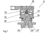
- the bearing element 6 is shown in detail, it being evident that a housing 23 is fastened to the holding arm 5 via a screw connection.
- a vertically displaceable intermediate part 24 is received in the housing 23 in a rotationally fixed manner and can be displaced counter to the force of cup springs 25 which are arranged between the intermediate part 24 and the base part 23 .
- a ball bearing 26 is accommodated in the intermediate part 23, via which a fastening part 27 with an end flange 27' is rotatably mounted.
- the fastening part 27 here has a central recess for receiving a centering bolt 20' of the connecting part 20, which has a conical projection 20'' which engages in the central recess 3' of the coil core 3 in the winding position. From a comparison of 6 and 7 It can be seen that the connecting part 20 can be exchanged, so that an adaptation to different coil cores 3, in particular to coil cores 3 with central recesses 3' of different sizes, can be achieved in a simple manner.
- a bearing element 6 provided as a counter bearing for the rotary plate 2 means that no spindle guided through the central recess 3 ′ of the coil core has to be provided, so that the insertion and in particular the removal of the coil core 3 in or out of the device 1 is significantly simplified and thus the risk of injury for the operator of the device or for other people in the vicinity of the device is reduced.
Landscapes
- Engineering & Computer Science (AREA)
- Power Engineering (AREA)
- Manufacturing & Machinery (AREA)
- Storage Of Web-Like Or Filamentary Materials (AREA)
- Coil Winding Methods And Apparatuses (AREA)
Claims (11)
- Dispositif (1) destiné à enrouler un fil métallique (4) sur un noyau de bobine (3) pour la fabrication de bobines électriques avec au moins une assiette de rotation (2), qui est prévue pour recevoir le noyau de bobine (3), un dispositif de retenue (5') étant prévu à proximité du noyau de bobine (3) pour la fixation réglable d'un élément palier (6), qui est fixé au niveau d'un bras de retenue (5) disposé de manière essentiellement perpendiculaire par rapport à l'axe du noyau de bobine (3) si bien que pour le logement sans broche du noyau de bobine (3) pendant le bobinage, le noyau de bobine (3) est logé de manière à pouvoir tourner côté extrémités au moyen de l'assiette de rotation (2) et de l'élément palier (6), caractérisé en ce que le bras de retenue (5) peut pivoter entre une position de bobinage et une position de repos et/ou de changement, le bras de retenue (5) est disposé au choix de manière pivotante ou solidaire en rotation à l'aide d'un dispositif d'immobilisation (10), le montant (8) présente un élément de base intérieur (11) recouvert par un élément de douille (12) portant le bras de retenue (5) et le bras de retenue (5) est logé de manière réglable en hauteur et solidaire en rotation sur l'élément de douille (12).
- Dispositif (1) selon la revendication 1, caractérisé en ce que le bras de retenue (5) peut pivoter autour d'un axe disposé de manière parallèle par rapport à l'axe du noyau de bobine (3).
- Dispositif selon la revendication 1 ou 2, caractérisé en ce que le bras de retenue (5) est disposé de manière réglable en hauteur.
- Dispositif selon l'une quelconque des revendications 1 à 3, caractérisé en ce que le bras de retenue (5) est disposé au niveau d'un montant (8) essentiellement vertical.
- Dispositif selon la revendication 4, caractérisé en ce que l'élément de douille (12) est réglable en hauteur par rapport à l'élément de base (11) par le biais d'un dispositif de vissage (11', 16').
- Dispositif selon la revendication 5, caractérisé en ce que l'élément de douille (12) est disposé de manière solidaire en rotation dans sa position vissée la plus basse, de préférence par le biais d'une fixation à expansion.
- Dispositif selon l'une quelconque des revendications 1 à 6, caractérisé en ce qu'une saillie conique (20") de l'élément palier (6) est reçue pendant le bobinage du noyau de bobine (3) dans un évidement médian (3') du noyau de bobine (3).
- Dispositif selon l'une quelconque des revendications 1 à 7, caractérisé en ce que l'élément palier (6) présente un boîtier (23) disposé de manière solidaire en rotation sur le bras de retenue (5), dans lequel un élément intermédiaire (24) verticalement mobile contre une force de ressort est disposé de manière solidaire en rotation.
- Dispositif selon la revendication 8, caractérisé en ce qu'un roulement (26), en particulier un roulement à billes, au niveau duquel un élément de fixation (27) est logé de manière rotative, est reçu dans l'élément intermédiaire (24).
- Dispositif selon la revendication 9, caractérisé en ce qu'une bride (27') est prévue au niveau de l'élément de fixation (27) pour recevoir un élément de liaison (20) présentant la saillie conique (20").
- Dispositif selon l'une quelconque des revendications 1 à 10, caractérisé en ce que l'assiette de rotation (2) présente en son milieu un axe (19), qui est reçu dans un évidement médian (3') du noyau de bobine (3) lorsque le noyau de bobine (3) est en position rapportée.
Applications Claiming Priority (2)
| Application Number | Priority Date | Filing Date | Title |
|---|---|---|---|
| AT0033206U AT9546U1 (de) | 2006-04-24 | 2006-04-24 | Vorrichtung zum bewickeln eines spulenkerns |
| PCT/AT2007/000189 WO2007121502A1 (fr) | 2006-04-24 | 2007-04-24 | Dispositif destiné à enrouler un noyau de bobine |
Publications (3)
| Publication Number | Publication Date |
|---|---|
| EP2011131A1 EP2011131A1 (fr) | 2009-01-07 |
| EP2011131B1 EP2011131B1 (fr) | 2009-10-14 |
| EP2011131B2 true EP2011131B2 (fr) | 2022-05-11 |
Family
ID=38456745
Family Applications (1)
| Application Number | Title | Priority Date | Filing Date |
|---|---|---|---|
| EP07718405.9A Active EP2011131B2 (fr) | 2006-04-24 | 2007-04-24 | Dispositif destiné à enrouler un noyau de bobine |
Country Status (5)
| Country | Link |
|---|---|
| EP (1) | EP2011131B2 (fr) |
| AT (2) | AT9546U1 (fr) |
| DE (1) | DE502007001736D1 (fr) |
| ES (1) | ES2333627T3 (fr) |
| WO (1) | WO2007121502A1 (fr) |
Families Citing this family (2)
| Publication number | Priority date | Publication date | Assignee | Title |
|---|---|---|---|---|
| CN112919244A (zh) * | 2021-03-15 | 2021-06-08 | 浙江理工大学 | 一种弯管热塑用绕线装置 |
| CN114772385B (zh) * | 2022-04-22 | 2024-05-10 | 佛山达东机械有限公司 | 一种可绕线均匀的卷绕机 |
Family Cites Families (3)
| Publication number | Priority date | Publication date | Assignee | Title |
|---|---|---|---|---|
| US2514970A (en) | 1944-11-23 | 1950-07-11 | Western Electric Co | Chuck for winding apparatus |
| US3332633A (en) | 1965-04-01 | 1967-07-25 | Gen Electric | Coil winding apparatus |
| AT7486U1 (de) | 2004-03-26 | 2005-04-25 | Kaizen Consulting Gmbh | Vorrichtung zum bewickeln eines spulenkerns |
-
2006
- 2006-04-24 AT AT0033206U patent/AT9546U1/de not_active IP Right Cessation
-
2007
- 2007-04-24 AT AT07718405T patent/ATE445905T1/de active
- 2007-04-24 EP EP07718405.9A patent/EP2011131B2/fr active Active
- 2007-04-24 ES ES07718405T patent/ES2333627T3/es active Active
- 2007-04-24 DE DE502007001736T patent/DE502007001736D1/de active Active
- 2007-04-24 WO PCT/AT2007/000189 patent/WO2007121502A1/fr not_active Ceased
Also Published As
| Publication number | Publication date |
|---|---|
| AT9546U1 (de) | 2007-11-15 |
| EP2011131A1 (fr) | 2009-01-07 |
| DE502007001736D1 (de) | 2009-11-26 |
| ATE445905T1 (de) | 2009-10-15 |
| EP2011131B1 (fr) | 2009-10-14 |
| WO2007121502A1 (fr) | 2007-11-01 |
| ES2333627T3 (es) | 2010-02-24 |
Similar Documents
| Publication | Publication Date | Title |
|---|---|---|
| DE2264353C2 (de) | Vorrichtung zur Halterung eines Ersatzrades eines Kraftfahrzeuges | |
| DE202019103662U1 (de) | Wickelvorrichtung für einen Feuerwehrschlauch | |
| DE7821666U1 (de) | Speicher- und abgabevorrichtung fuer gestapelte gegenstaende | |
| CH687641A5 (de) | Sphorische Aufhaengung fuer ein technisches Instrument. | |
| EP0222375A2 (fr) | Dispositif de relèvement applicable à des lits d'hôpital | |
| EP2011131B2 (fr) | Dispositif destiné à enrouler un noyau de bobine | |
| DE69406934T2 (de) | Kabeltrommelgestell | |
| EP2387542A2 (fr) | Tête de bouchage pour machine à boucher des récipients et machine à boucher des récipients correspondante | |
| DE19528901B4 (de) | Höhenverstellbarer Fuß für Küchengeräte oder Möbel | |
| EP1607364A2 (fr) | Systeme de contrepoids d'une grue | |
| DE2758357A1 (de) | Speicher- und ausgabevorrichtung fuer gestapelte gegenstaende | |
| DE3438179C2 (fr) | ||
| EP0096836B1 (fr) | Dispositif pour produire des bobines de rotor ou de stator pour machines électriques | |
| CH315275A (de) | Zwischen dem Sitz und dem diesen tragenden Ständer eines Drehstuhls angeordnete Sperrvorrichtung zum zeitweiligen Sperren des Sitzes gegen Verdrehung | |
| DE29702673U1 (de) | Federspanner zum Spannen von Schraubenfedern mit zwei Druckplatten | |
| DE3937462C2 (de) | Ablaufhaspel für Wickel, insbesondere Drahtwickel | |
| DE2507200C2 (de) | Messerscheibe für Rasenmäher | |
| DE68921747T2 (de) | Spulenaufhänger. | |
| EP0131094A1 (fr) | Dispositif de fixation de bobines | |
| DE19725059C2 (de) | Koppeleinrichtung für ein Möbelverbundsystem | |
| AT10691U1 (de) | Ladekran mit in transportstellung bringbarem lastaufnahmemittel | |
| DE19931758C2 (de) | Trageeinrichtung zum Heben und Senken von Lasten | |
| EP0963933A1 (fr) | Distributeur de rouleaux de bandes adhésives | |
| DE3705181A1 (de) | Kernreaktorbrennelement | |
| DE102005043774B4 (de) | Auszahlvorrichtung für mindestens eine Münztube eines Münzgerätes |
Legal Events
| Date | Code | Title | Description |
|---|---|---|---|
| PUAI | Public reference made under article 153(3) epc to a published international application that has entered the european phase |
Free format text: ORIGINAL CODE: 0009012 |
|
| 17P | Request for examination filed |
Effective date: 20080908 |
|
| AK | Designated contracting states |
Kind code of ref document: A1 Designated state(s): AT BE BG CH CY CZ DE DK EE ES FI FR GB GR HU IE IS IT LI LT LU LV MC MT NL PL PT RO SE SI SK TR |
|
| AX | Request for extension of the european patent |
Extension state: AL BA HR MK RS |
|
| GRAP | Despatch of communication of intention to grant a patent |
Free format text: ORIGINAL CODE: EPIDOSNIGR1 |
|
| DAX | Request for extension of the european patent (deleted) | ||
| GRAS | Grant fee paid |
Free format text: ORIGINAL CODE: EPIDOSNIGR3 |
|
| GRAA | (expected) grant |
Free format text: ORIGINAL CODE: 0009210 |
|
| AK | Designated contracting states |
Kind code of ref document: B1 Designated state(s): AT BE BG CH CY CZ DE DK EE ES FI FR GB GR HU IE IS IT LI LT LU LV MC MT NL PL PT RO SE SI SK TR |
|
| REG | Reference to a national code |
Ref country code: GB Ref legal event code: FG4D Free format text: NOT ENGLISH |
|
| REG | Reference to a national code |
Ref country code: CH Ref legal event code: EP |
|
| REG | Reference to a national code |
Ref country code: IE Ref legal event code: FG4D |
|
| REF | Corresponds to: |
Ref document number: 502007001736 Country of ref document: DE Date of ref document: 20091126 Kind code of ref document: P |
|
| REG | Reference to a national code |
Ref country code: ES Ref legal event code: FG2A Ref document number: 2333627 Country of ref document: ES Kind code of ref document: T3 |
|
| LTIE | Lt: invalidation of european patent or patent extension |
Effective date: 20091014 |
|
| NLV1 | Nl: lapsed or annulled due to failure to fulfill the requirements of art. 29p and 29m of the patents act | ||
| PG25 | Lapsed in a contracting state [announced via postgrant information from national office to epo] |
Ref country code: PT Free format text: LAPSE BECAUSE OF FAILURE TO SUBMIT A TRANSLATION OF THE DESCRIPTION OR TO PAY THE FEE WITHIN THE PRESCRIBED TIME-LIMIT Effective date: 20100215 Ref country code: IS Free format text: LAPSE BECAUSE OF FAILURE TO SUBMIT A TRANSLATION OF THE DESCRIPTION OR TO PAY THE FEE WITHIN THE PRESCRIBED TIME-LIMIT Effective date: 20100214 Ref country code: LT Free format text: LAPSE BECAUSE OF FAILURE TO SUBMIT A TRANSLATION OF THE DESCRIPTION OR TO PAY THE FEE WITHIN THE PRESCRIBED TIME-LIMIT Effective date: 20091014 Ref country code: FI Free format text: LAPSE BECAUSE OF FAILURE TO SUBMIT A TRANSLATION OF THE DESCRIPTION OR TO PAY THE FEE WITHIN THE PRESCRIBED TIME-LIMIT Effective date: 20091014 Ref country code: SE Free format text: LAPSE BECAUSE OF FAILURE TO SUBMIT A TRANSLATION OF THE DESCRIPTION OR TO PAY THE FEE WITHIN THE PRESCRIBED TIME-LIMIT Effective date: 20091014 |
|
| REG | Reference to a national code |
Ref country code: IE Ref legal event code: FD4D |
|
| PG25 | Lapsed in a contracting state [announced via postgrant information from national office to epo] |
Ref country code: SI Free format text: LAPSE BECAUSE OF FAILURE TO SUBMIT A TRANSLATION OF THE DESCRIPTION OR TO PAY THE FEE WITHIN THE PRESCRIBED TIME-LIMIT Effective date: 20091014 Ref country code: LV Free format text: LAPSE BECAUSE OF FAILURE TO SUBMIT A TRANSLATION OF THE DESCRIPTION OR TO PAY THE FEE WITHIN THE PRESCRIBED TIME-LIMIT Effective date: 20091014 Ref country code: PL Free format text: LAPSE BECAUSE OF FAILURE TO SUBMIT A TRANSLATION OF THE DESCRIPTION OR TO PAY THE FEE WITHIN THE PRESCRIBED TIME-LIMIT Effective date: 20091014 |
|
| PLBI | Opposition filed |
Free format text: ORIGINAL CODE: 0009260 |
|
| PG25 | Lapsed in a contracting state [announced via postgrant information from national office to epo] |
Ref country code: RO Free format text: LAPSE BECAUSE OF FAILURE TO SUBMIT A TRANSLATION OF THE DESCRIPTION OR TO PAY THE FEE WITHIN THE PRESCRIBED TIME-LIMIT Effective date: 20091014 Ref country code: IE Free format text: LAPSE BECAUSE OF FAILURE TO SUBMIT A TRANSLATION OF THE DESCRIPTION OR TO PAY THE FEE WITHIN THE PRESCRIBED TIME-LIMIT Effective date: 20091014 Ref country code: DK Free format text: LAPSE BECAUSE OF FAILURE TO SUBMIT A TRANSLATION OF THE DESCRIPTION OR TO PAY THE FEE WITHIN THE PRESCRIBED TIME-LIMIT Effective date: 20091014 Ref country code: EE Free format text: LAPSE BECAUSE OF FAILURE TO SUBMIT A TRANSLATION OF THE DESCRIPTION OR TO PAY THE FEE WITHIN THE PRESCRIBED TIME-LIMIT Effective date: 20091014 Ref country code: BG Free format text: LAPSE BECAUSE OF FAILURE TO SUBMIT A TRANSLATION OF THE DESCRIPTION OR TO PAY THE FEE WITHIN THE PRESCRIBED TIME-LIMIT Effective date: 20100114 |
|
| PLAX | Notice of opposition and request to file observation + time limit sent |
Free format text: ORIGINAL CODE: EPIDOSNOBS2 |
|
| 26 | Opposition filed |
Opponent name: AUMANN GMBH Effective date: 20100714 |
|
| PG25 | Lapsed in a contracting state [announced via postgrant information from national office to epo] |
Ref country code: SK Free format text: LAPSE BECAUSE OF FAILURE TO SUBMIT A TRANSLATION OF THE DESCRIPTION OR TO PAY THE FEE WITHIN THE PRESCRIBED TIME-LIMIT Effective date: 20091014 Ref country code: CZ Free format text: LAPSE BECAUSE OF FAILURE TO SUBMIT A TRANSLATION OF THE DESCRIPTION OR TO PAY THE FEE WITHIN THE PRESCRIBED TIME-LIMIT Effective date: 20091014 |
|
| PG25 | Lapsed in a contracting state [announced via postgrant information from national office to epo] |
Ref country code: GR Free format text: LAPSE BECAUSE OF FAILURE TO SUBMIT A TRANSLATION OF THE DESCRIPTION OR TO PAY THE FEE WITHIN THE PRESCRIBED TIME-LIMIT Effective date: 20100115 |
|
| BERE | Be: lapsed |
Owner name: NHKM CONSULTING GMBH Effective date: 20100430 |
|
| PG25 | Lapsed in a contracting state [announced via postgrant information from national office to epo] |
Ref country code: MC Free format text: LAPSE BECAUSE OF NON-PAYMENT OF DUE FEES Effective date: 20100430 |
|
| PLBB | Reply of patent proprietor to notice(s) of opposition received |
Free format text: ORIGINAL CODE: EPIDOSNOBS3 |
|
| PG25 | Lapsed in a contracting state [announced via postgrant information from national office to epo] |
Ref country code: BE Free format text: LAPSE BECAUSE OF NON-PAYMENT OF DUE FEES Effective date: 20100430 Ref country code: IT Free format text: LAPSE BECAUSE OF NON-PAYMENT OF DUE FEES Effective date: 20100424 |
|
| PG25 | Lapsed in a contracting state [announced via postgrant information from national office to epo] |
Ref country code: MT Free format text: LAPSE BECAUSE OF FAILURE TO SUBMIT A TRANSLATION OF THE DESCRIPTION OR TO PAY THE FEE WITHIN THE PRESCRIBED TIME-LIMIT Effective date: 20091014 |
|
| PLAY | Examination report in opposition despatched + time limit |
Free format text: ORIGINAL CODE: EPIDOSNORE2 |
|
| PLBC | Reply to examination report in opposition received |
Free format text: ORIGINAL CODE: EPIDOSNORE3 |
|
| REG | Reference to a national code |
Ref country code: CH Ref legal event code: PL |
|
| GBPC | Gb: european patent ceased through non-payment of renewal fee |
Effective date: 20110424 |
|
| PG25 | Lapsed in a contracting state [announced via postgrant information from national office to epo] |
Ref country code: LI Free format text: LAPSE BECAUSE OF NON-PAYMENT OF DUE FEES Effective date: 20110430 Ref country code: CH Free format text: LAPSE BECAUSE OF NON-PAYMENT OF DUE FEES Effective date: 20110430 |
|
| PG25 | Lapsed in a contracting state [announced via postgrant information from national office to epo] |
Ref country code: GB Free format text: LAPSE BECAUSE OF NON-PAYMENT OF DUE FEES Effective date: 20110424 |
|
| PG25 | Lapsed in a contracting state [announced via postgrant information from national office to epo] |
Ref country code: CY Free format text: LAPSE BECAUSE OF FAILURE TO SUBMIT A TRANSLATION OF THE DESCRIPTION OR TO PAY THE FEE WITHIN THE PRESCRIBED TIME-LIMIT Effective date: 20091014 |
|
| PG25 | Lapsed in a contracting state [announced via postgrant information from national office to epo] |
Ref country code: NL Free format text: LAPSE BECAUSE OF FAILURE TO SUBMIT A TRANSLATION OF THE DESCRIPTION OR TO PAY THE FEE WITHIN THE PRESCRIBED TIME-LIMIT Effective date: 20091014 Ref country code: HU Free format text: LAPSE BECAUSE OF FAILURE TO SUBMIT A TRANSLATION OF THE DESCRIPTION OR TO PAY THE FEE WITHIN THE PRESCRIBED TIME-LIMIT Effective date: 20100415 Ref country code: LU Free format text: LAPSE BECAUSE OF NON-PAYMENT OF DUE FEES Effective date: 20100424 |
|
| PG25 | Lapsed in a contracting state [announced via postgrant information from national office to epo] |
Ref country code: TR Free format text: LAPSE BECAUSE OF FAILURE TO SUBMIT A TRANSLATION OF THE DESCRIPTION OR TO PAY THE FEE WITHIN THE PRESCRIBED TIME-LIMIT Effective date: 20091014 |
|
| REG | Reference to a national code |
Ref country code: CH Ref legal event code: PK Free format text: DAS PRIORITAETSAKTENZEICHEN WURDE BERICHTIGT: AT 33206 U / 24.04.2006 |
|
| PLCK | Communication despatched that opposition was rejected |
Free format text: ORIGINAL CODE: EPIDOSNREJ1 |
|
| APBM | Appeal reference recorded |
Free format text: ORIGINAL CODE: EPIDOSNREFNO |
|
| APBP | Date of receipt of notice of appeal recorded |
Free format text: ORIGINAL CODE: EPIDOSNNOA2O |
|
| APAH | Appeal reference modified |
Free format text: ORIGINAL CODE: EPIDOSCREFNO |
|
| APBQ | Date of receipt of statement of grounds of appeal recorded |
Free format text: ORIGINAL CODE: EPIDOSNNOA3O |
|
| REG | Reference to a national code |
Ref country code: FR Ref legal event code: PLFP Year of fee payment: 9 |
|
| PGFP | Annual fee paid to national office [announced via postgrant information from national office to epo] |
Ref country code: FR Payment date: 20150430 Year of fee payment: 9 |
|
| REG | Reference to a national code |
Ref country code: FR Ref legal event code: ST Effective date: 20161230 |
|
| PG25 | Lapsed in a contracting state [announced via postgrant information from national office to epo] |
Ref country code: FR Free format text: LAPSE BECAUSE OF NON-PAYMENT OF DUE FEES Effective date: 20160502 |
|
| PGFP | Annual fee paid to national office [announced via postgrant information from national office to epo] |
Ref country code: AT Payment date: 20181025 Year of fee payment: 12 |
|
| PGFP | Annual fee paid to national office [announced via postgrant information from national office to epo] |
Ref country code: IT Payment date: 20181018 Year of fee payment: 12 Ref country code: ES Payment date: 20181030 Year of fee payment: 12 |
|
| REG | Reference to a national code |
Ref country code: AT Ref legal event code: MM01 Ref document number: 445905 Country of ref document: AT Kind code of ref document: T Effective date: 20190424 |
|
| PG25 | Lapsed in a contracting state [announced via postgrant information from national office to epo] |
Ref country code: AT Free format text: LAPSE BECAUSE OF NON-PAYMENT OF DUE FEES Effective date: 20190424 |
|
| PG25 | Lapsed in a contracting state [announced via postgrant information from national office to epo] |
Ref country code: IT Free format text: LAPSE BECAUSE OF NON-PAYMENT OF DUE FEES Effective date: 20190424 |
|
| REG | Reference to a national code |
Ref country code: ES Ref legal event code: FD2A Effective date: 20200901 |
|
| PLAB | Opposition data, opponent's data or that of the opponent's representative modified |
Free format text: ORIGINAL CODE: 0009299OPPO |
|
| PLAB | Opposition data, opponent's data or that of the opponent's representative modified |
Free format text: ORIGINAL CODE: 0009299OPPO |
|
| R26 | Opposition filed (corrected) |
Opponent name: AUMANN GMBH Effective date: 20100714 |
|
| R26 | Opposition filed (corrected) |
Opponent name: AUMANN GMBH Effective date: 20100715 |
|
| PG25 | Lapsed in a contracting state [announced via postgrant information from national office to epo] |
Ref country code: ES Free format text: LAPSE BECAUSE OF NON-PAYMENT OF DUE FEES Effective date: 20190425 |
|
| APBU | Appeal procedure closed |
Free format text: ORIGINAL CODE: EPIDOSNNOA9O |
|
| PLAP | Information related to despatch of examination report in opposition + time limit deleted |
Free format text: ORIGINAL CODE: EPIDOSDORE2 |
|
| PLAT | Information related to reply to examination report in opposition deleted |
Free format text: ORIGINAL CODE: EPIDOSDORE3 |
|
| PLAY | Examination report in opposition despatched + time limit |
Free format text: ORIGINAL CODE: EPIDOSNORE2 |
|
| PLBC | Reply to examination report in opposition received |
Free format text: ORIGINAL CODE: EPIDOSNORE3 |
|
| RIC2 | Information provided on ipc code assigned after grant |
Ipc: H01F 41/092 20160101ALI20210917BHEP Ipc: H01F 41/064 20160101ALI20210917BHEP Ipc: B65H 54/553 20060101ALI20210917BHEP Ipc: H01F 41/06 20160101AFI20210917BHEP |
|
| PUAH | Patent maintained in amended form |
Free format text: ORIGINAL CODE: 0009272 |
|
| STAA | Information on the status of an ep patent application or granted ep patent |
Free format text: STATUS: PATENT MAINTAINED AS AMENDED |
|
| 27A | Patent maintained in amended form |
Effective date: 20220511 |
|
| AK | Designated contracting states |
Kind code of ref document: B2 Designated state(s): AT BE BG CH CY CZ DE DK EE ES FI FR GB GR HU IE IS IT LI LT LU LV MC MT NL PL PT RO SE SI SK TR |
|
| REG | Reference to a national code |
Ref country code: DE Ref legal event code: R102 Ref document number: 502007001736 Country of ref document: DE |
|
| P01 | Opt-out of the competence of the unified patent court (upc) registered |
Effective date: 20230519 |
|
| PGFP | Annual fee paid to national office [announced via postgrant information from national office to epo] |
Ref country code: DE Payment date: 20250423 Year of fee payment: 19 |