EP2011644A2 - Unité fonctionnelle pour une presse rotative et presse rotative dotée d'une telle unité fonctionnelle - Google Patents
Unité fonctionnelle pour une presse rotative et presse rotative dotée d'une telle unité fonctionnelle Download PDFInfo
- Publication number
- EP2011644A2 EP2011644A2 EP08011303A EP08011303A EP2011644A2 EP 2011644 A2 EP2011644 A2 EP 2011644A2 EP 08011303 A EP08011303 A EP 08011303A EP 08011303 A EP08011303 A EP 08011303A EP 2011644 A2 EP2011644 A2 EP 2011644A2
- Authority
- EP
- European Patent Office
- Prior art keywords
- mounting
- functional unit
- component
- opening
- unit according
- Prior art date
- Legal status (The legal status is an assumption and is not a legal conclusion. Google has not performed a legal analysis and makes no representation as to the accuracy of the status listed.)
- Withdrawn
Links
- 238000004458 analytical method Methods 0.000 description 22
- 238000004519 manufacturing process Methods 0.000 description 11
- 238000011161 development Methods 0.000 description 7
- 230000018109 developmental process Effects 0.000 description 7
- 239000003921 oil Substances 0.000 description 7
- 238000012800 visualization Methods 0.000 description 7
- 230000002349 favourable effect Effects 0.000 description 6
- 229920000459 Nitrile rubber Polymers 0.000 description 4
- 238000005516 engineering process Methods 0.000 description 4
- 239000003795 chemical substances by application Substances 0.000 description 3
- 230000000694 effects Effects 0.000 description 3
- 239000000463 material Substances 0.000 description 3
- 230000002028 premature Effects 0.000 description 3
- 230000001419 dependent effect Effects 0.000 description 2
- 238000005266 casting Methods 0.000 description 1
- 239000003086 colorant Substances 0.000 description 1
- 238000010276 construction Methods 0.000 description 1
- 229920001971 elastomer Polymers 0.000 description 1
- 238000009434 installation Methods 0.000 description 1
- 239000010687 lubricating oil Substances 0.000 description 1
- 238000003801 milling Methods 0.000 description 1
- 230000036316 preload Effects 0.000 description 1
- 230000000630 rising effect Effects 0.000 description 1
- 239000000565 sealant Substances 0.000 description 1
Images



Classifications
-
- B—PERFORMING OPERATIONS; TRANSPORTING
- B41—PRINTING; LINING MACHINES; TYPEWRITERS; STAMPS
- B41F—PRINTING MACHINES OR PRESSES
- B41F13/00—Common details of rotary presses or machines
- B41F13/0024—Frames
Definitions
- the invention relates to a rotary printing press, and more particularly to a functional unit for a rotary printing press and a rotary printing machine equipped with such a functional unit, wherein improved operating conditions and thus an increased service life of the functional unit are achieved by constant and defined mounting conditions in the functional unit.
- Examples of such a staggered arrangement of the functional units of the rotary printing press are the printing presses "REGIOMAN” and “GEOMAN” manufactured by MAN Roland Druckmaschinen AG.
- these printing machines two 8-cylinder printing units or H printing units (rubber-rubber) are stacked to form a printing tower, whereby, for example, a so-called 4/4-color printing (the application of four colors on each side of a paper web to be printed ) can be realized with short railways.
- the invention has for its object to provide a functional unit for a rotary printing press and a rotary printing press with such a functional unit, wherein in the functional unit in a cost-effective manner by weight load induced bias voltages are reduced to storage elements for their components or avoided.
- a functional unit for a rotary printing press has a mounting unit for receiving at least one component of the functional unit.
- the mounting unit has at least one mounting portion having a predetermined thickness, at least one mounting hole formed in the mounting portion and accommodating the at least one component via a bearing member, and a support portion on which a weight load can be supported.
- a first component-free opening which is at least as large as a cross-sectional dimension of the mounting opening in a cross-sectional dimension.
- FE analysis computer-aided finite element analysis
- the inventive design of the mounting unit to introduce the mounting holes already in the production of the individual functional unit.
- component-free opening is to be understood in the context of the invention that for such an opening with respect to the functional assembly of the functional unit, such as the storage of components, the passage of cables, hoses or shafts or axes, etc., no need exists, but such an opening in addition to the functionally necessary openings, such as the mounting holes, is provided for shielding the mounting holes against deformation forces or to redirect the deformation forces.
- the mounting opening is formed as through the thickness of the mounting portion extending through opening.
- the first component-free opening is formed as through the thickness of the mounting portion extending through opening.
- the derivative of the deformation induced by weight load deformation forces is further improved, especially if the mounting hole is formed as a through hole.
- the component-free opening is arranged in a main direction of action of the weight load with respect to the mounting opening in front of the mounting opening.
- the weight forces induced by the weight load are derived even better from the mounting opening to adjacent sections of the mounting unit, since the component-free opening or the relief section is arranged in an optimal position in front of the mounting opening.
- the first component-free opening is formed as a slot having a predetermined width and a predetermined length.
- the length of the slot is selected so that it is, for example, as large as or larger than a width or a diameter of the mounting hole. In this way, in the direction of action of the weight load or the deformation forces, the entire area of the mounting opening is reliably shielded from the deformation forces.
- the width of the slot can vary depending on the applied weight load, manufacturing capabilities and / or design of the mounting unit or be selected depending on it.
- the component-free opening of course, as a circular opening, such as a hole can be formed.
- one Cross-sectional dimension (in this case the diameter) of the device-free opening is at least as large as a cross-sectional dimension (such as in the case of a bore diameter) of the mounting hole.
- the device-free opening completely covers a portion of the mounting opening defined by its cross-sectional dimension, so that the mounting opening is shielded against the effect of the weight load.
- the first component-free opening designed as a slot extends at least in sections in a straight line along its length.
- the slot may be constituted, for example, by a single rectilinear portion, a plurality of rectilinear sections optionally arranged at an angle, or a combination of e.g. be formed arcuate and rectilinear sections.
- the first component-free opening designed as a slot extends along its length at least in a section transverse to the main direction of action of the weight load.
- the slot may extend completely along its length transverse to the main direction of action or may extend in only a portion of its length transverse to the main direction of action and the remainder of its length in a different direction.
- a second component-free opening is provided which is at least as large as a cross-sectional dimension of the mounting opening in a cross-sectional dimension.
- a component-free opening or a relief cut can be provided, wherein the exact location of the two relief cuts is dependent on the design of the mounting unit.
- the second component-free opening is formed as through the thickness of the mounting portion extending through opening.
- the derivative of the deformation induced by weight load deformation forces or reaction forces is further improved, especially if the mounting hole is formed as a through hole.
- the second component-free opening is formed as a slot having a predetermined width and a predetermined length.
- the length of the slot is selected so that it is, for example, as large as or larger than a width or a diameter of the mounting hole. In this way, in the direction of action of the deformation forces or reaction forces, the entire area of the mounting opening is reliably shielded from the deformation forces.
- the width of the slot can, depending on the applied weight load, manufacturing technology Possibilities and / or design of the mounting unit vary or be chosen depending on it.
- the second device-free aperture is of course also referred to as a circular aperture, e.g. a bore can be formed. It is important in this context only that a cross-sectional dimension (in this case, the diameter) of the device-free aperture be at least as large as a cross-sectional dimension (such as in the case of a bore diameter) of the mounting aperture. In other words, the second component-free opening completely covers a region of the mounting opening defined by its cross-sectional dimension, so that the mounting opening is shielded against the effect of the weight load or the reaction forces.
- the slot formed as a second component-free opening along its length extends at least partially rectilinear.
- the slot may be constituted, for example, by a single rectilinear portion, a plurality of rectilinear sections optionally arranged at an angle, or a combination of e.g. be formed arcuate and rectilinear sections.
- the slot formed as a second component-free opening extends along its length at least in a section transverse to the main direction of action of the weight load.
- the slot may extend completely along its length transverse to the main direction of action, or may only extend with it extend part of its length transverse to the main direction of action and with the remainder of its length in a different direction.
- the second component-free opening is formed twice mirror-inverted to the first component-free opening.
- the second component-free opening is embodied in a mirrored manner to the first component-free opening via two mirror axes arranged perpendicular to one another.
- the at least one mounting opening is formed as a circular opening of predetermined diameter.
- the mounting aperture may be formed, for example, as a bore or as a preformed circular aperture (e.g., a cast aperture in a casting), the cross-sectional dimension of the aperture being formed by its diameter.
- a cross-sectional dimension of the first and possibly the second component-free opening is at least as large as the diameter of the assembly opening, i. equal to or greater than this.
- the mounting unit has at least two mounting unit elements.
- At least one mounting opening is formed in each of the mounting unit elements.
- the functional unit is a printing unit.
- the functional unit is not limited to a printing unit such as an H printing unit is, but for example, a folder, a paster or a dryer can be.
- the mounting unit elements are formed as side walls of the printing unit.
- the mounting unit members form the side wall of the operating side of the printing unit and the side wall of the driving side of the printing unit.
- the at least one component is a cylinder of the printing unit, which is rotatably mounted via respective bearing elements (for example roller bearings and / or ball bearings) in two opposite mounting openings of the two side walls of the printing unit.
- respective bearing elements for example roller bearings and / or ball bearings
- the cylinder may be, for example, a plate cylinder, a blanket cylinder and / or an impression cylinder of the printing unit.
- the assembly openings of all cylinders or parts of the printing unit rotatably mounted in the side walls can preferably be provided with component-free openings or relief cuts.
- the device-free openings or relief cuts are formed as through-holes, these openings are preferably made with a flexible and oil-resistant sealant, such as e.g. Nitrile rubber, are closed or filled, so that neither dirt enter the functional unit nor any medium, such. Lubricating oil from the functional unit can escape.
- a flexible and oil-resistant sealant such as e.g. Nitrile rubber
- an assembly unit 100 of a functional unit (not fully illustrated and not designated) for a rotary printing press is shown.
- the functional unit is a so-called H-printing unit (hereinafter simply printing unit) for a web-fed rotary printing press.
- the mounting unit 100 is according to this case, the base frame 100 of the printing unit to which the components of the printing unit, such as plate cylinder, blanket cylinder, inking, dampening, drives, control technology, etc., are to be included or mounted.
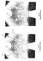
- the mounting unit or the base frame 100 at least two mounting unit elements, namely according to this case, the two side walls 101 (operating side SI) and 102 (drive side SII) of the printing unit, which side walls 101, 102 in which in Figures 1A to 1D are formed according to an initial state based on the FE analysis.
- the two side walls 101 (operating side SI) and 102 (drive side SII) of the printing unit which side walls 101, 102 in which in Figures 1A to 1D are formed according to an initial state based on the FE analysis.
- the base 100 has at least one mounting portion 110 having a predetermined thickness.
- each side wall 101, 102 of the base 100 of the printing unit has one Mounting portion 110 in which a plurality of mounting holes are formed.
- a storage element such as a ball bearing or a roller bearing to mount, via which the components are received or stored on the side walls 101, 102 in the mounting holes.
- the mounting holes are formed as circular through holes 130 of predetermined diameter passing through the thickness of the mounting portion 110 and serve to receive the cylinder bearings of the printing unit.
- the base frame 100 of the printing unit further comprises a support portion 120, on which a weight load can be supported.
- the side walls 101, 102 of the base frame 100 have on their respective upper side a machined surface on which a second printing unit (as in the previously described "REGIOMAN” or “GEOMAN” printing press from MAN Roland Druckmaschinen AG) can be set up ,
- the load bearing section 120 was subjected to a weight load of 25 t by way of example. Further, the sidewall 101 and 102, respectively, for FE analysis was considered a smooth sidewall without ribbing.
- the through-holes 130 with an applied weight load of 25 tons experience a deformation of approximately 0.00633 mm to approximately 0.019 mm. That is, at higher weight load, as is common in the described printing units and which will increase even more by the current trend towards compact printing units with more pressure points, a relatively large deformation of the through holes 130 (here the bearing bores for the cylinders of the printing unit) given. This can generate radial biases in the cylinder bearings accommodated in the through bores 130, which can lead to premature failure of the cylinder bearings.
- the weight load with respect to the mounting holes or through-holes 130 unfolds a main direction of action in which the largest deformation of the through-holes 130 takes place.
- the main direction of action HR of the weight load can, of course, be different than in the illustrated case.
- the through holes 130 are deformed by the weight load induced deformation forces in cross section from originally a circle to an ellipse.
- FIGS. 2A to 2D a first embodiment of the invention described.
- the in the FIGS. 2A to 2D illustrated assembly unit 200 of a functional unit substantially corresponds to those in the FIGS. 1A to 1B is shown.
- the functional unit is a so-called H-printing unit (hereinafter simply printing unit) for a web-fed rotary printing press
- the mounting unit is the base frame 200 of the printing unit, wherein the base frame 200 has at least two mounting unit elements, according to this embodiment of Invention, the two side walls 201 (operating side SI) and 202 (drive side SII) of the printing unit are.
- the two side walls 201 (operating side SI) and 202 (drive side SII) of the printing unit are.
- FIGS. 2A to 2D only the side wall 201 or 202 of the printing unit shown.
- the base frame 200 has at least one mounting portion 210 having a predetermined thickness.
- each side wall 201, 202 of the base frame 200 of the printing unit has a mounting portion 210 in which a plurality of mounting holes are formed.
- a storage element is to be mounted in the mounting holes, via which the components are received or stored on the side walls 201, 202.
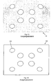
- the mounting holes are formed as circular through holes 230 of predetermined diameter passing through the thickness of the mounting portion 210, and serve to receive the cylinder bearings of the printing unit.
- a first component-free opening 240 which is at least as large as the diameter of the respective through-hole 230 in a cross-sectional dimension.
- a second component-free opening 250 is provided, which in a cross-sectional dimension at least as large as the diameter of the respective through hole 230 is.
- the first and second component-free openings are respectively formed as slits 240 and 250 extending through the thickness of the mounting portion 210 and having a cross-section of a predetermined width and a predetermined length.
- the length of a through hole 230 associated slots 240, 250 is at least as large as the diameter of the respective through hole 230. As in the FIGS. 2A to 2D 2, according to this first embodiment of the invention, the length of the slots 240, 250 is greater than the diameter of the respective through-hole 230.
- the width of the slots is 10 mm according to this embodiment of the invention.
- relief cuts or slits 240, 250 are introduced into the side walls 201, 202 of the printing unit above and below the cylinder bores or through bores 230.
- the slots 240, 250 extend along their length in a straight line and horizontally. Further, the slots 240, 250 are filled with an elastic and oil-resistant mass, such as nitrile rubber, to prevent ingress of dirt and leakage, e.g. To avoid oil.
- an elastic and oil-resistant mass such as nitrile rubber
- the base frame 200 of the printing unit further comprises a support portion 220 on which a weight load can be supported.
- the side walls 201, 202 of the base frame 200 have on their respective upper side a machined surface on which a second printing unit (as in the previously described "REGIOMAN” or “GEOMAN” printing press from MAN Roland Druckmaschinen AG) can be set up ,
- FIGS. 2A to 2D underlying FE analysis was the support section 220 in the same manner as in the Figures 1A to 1D subjected to a weight load of 25 t. Further, the side wall 201 or 202 for the FE analysis was again adopted as a smooth sidewall without ribbing.
- the weight load leads to deformations of the side wall 201 and 202, wherein the deformations correspond approximately to those with respect to the Figures 1A to 1D have been described.
- a slot 240 is provided, whose length is at least as large as the diameter of the the through holes 230 are shielded against the deformation forces induced by the weight load or the deformation forces are derived to adjacent portions of the side wall 201 and 202, so that the through holes 230 are not or only minimally deformed and maintain their original circular shape.
- a slot 250 (second component-free openings) whose length is at least as large as the diameter of the respective through-hole 230 is additionally provided on the opposite side of the respective through-holes 230 to the slots 240 (first component-free openings), the through-holes 230 become also reliably shielded against from the other side or down to these acting deformation forces or reaction forces.
- the weight load with respect to the through-holes 230 unfolds a main direction of action in which the greatest deformation forces would act on the through-holes 230.
- the main direction of action HR of the weight load can, of course, be different than in the illustrated case.
- the slots 240 are arranged in the main direction of action HR of the weight load with respect to the respective through-holes 230 in front of the through-holes 230, whereby the through-holes 230 are particularly well shielded against the deformation forces.
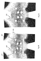
- FIGS. 3A to 3D a second embodiment of the invention is shown, which with the exception of the design of the device-free openings with the first embodiment of the invention is identical. In the following, therefore, only the device-free openings are described in detail, wherein the same reference numerals are used for the identical elements as in the first embodiment.
- FIGS. 3A to 3D underlying FE analysis was the support section 220 again in the same manner as in the Figures 1A to 1D and 2A to 2D subjected to a weight load of 25 t. Further, the side wall 201 or 202 for the FE analysis was again adopted as a smooth sidewall without ribbing.
- a slot 260a arranged between two through-holes 230 takes over the function of both the first component-free opening (for the respective lower through-hole 230) and the second component-free opening (for the respective upper through-hole 230).
- the width of the slots is 11 mm according to this embodiment of the invention.
- the weight load leads to deformations of the side wall 201 and 202, wherein the deformations correspond approximately to those with respect to the Figures 1A to 1D have been described.
- a slot 240a and 260a is provided, whose length is at least as large as the diameter of the respective through-hole 230, the through-holes 230 are shielded against the weight load induced deformation forces or For example, the deformation forces are dissipated to adjacent portions of the side walls 201 and 202, respectively, so that the through-holes 230 are not or only minimally deformed and retain their original circular shape.
- the through-holes 230 are also reliably shielded against deformation forces or reaction forces acting on the other side or on the bottom.
- the weight load with respect to the through-holes 230 also unfolds a main direction of action in which the greatest deformation forces would act on the through-holes 230.
- the main direction of action HR of the weight load can, of course, be different than in the illustrated case.
- the slots 240a and 260a in the main direction of action HR of the weight load with respect to the respective through-holes 230 are disposed in front of the through-holes 230, whereby the through-holes 230 are particularly well shielded against the deformation forces.
- the slots 240a, 250a and 260a are again filled with an elastic and oil-resistant mass, e.g. Nitrile rubber, filled to prevent ingress of dirt and leakage of e.g. To avoid oil.
- an elastic and oil-resistant mass e.g. Nitrile rubber
- the second embodiment of the invention is from a manufacturing point of view and from a cost point of view, a particularly favorable design, since less production costs incurred for the slots.
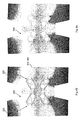
- FIGS. 4A to 4D a third embodiment of the invention is shown, which is identical to the first and the second embodiment of the invention, with the exception of the design of the device-free openings. In the following, therefore, only the device-free openings are described in detail, wherein the same reference numerals are used for the identical elements as in the first embodiment.
- FIGS. 4A to 4D underlying FE analysis was the support section 220 again in the same manner as in the Figures 1A to 1D . 2A to 2D and 3A to 3D subjected to a weight load of 25 t. Further, the side wall 201 or 202 for the FE analysis was again adopted as a smooth sidewall without ribbing.
- the weight load with respect to the through-holes 230 unfolds a main direction of action in which the greatest deformation forces would act on the through-holes 230.
- the main direction of action HR of the weight load can, of course, be different than in the illustrated case.
- the weight load leads to deformations of the side wall 201 and 202, wherein the deformations correspond approximately to those with respect to the Figures 1A to 1D have been described.
- a slot 240b is provided between the support portion 220 and each through-hole 230, the length of which is at least as large as the diameter of the respective through-hole 230, the through-holes 230 are shielded against the deformation forces induced by the weight load or the deformation forces derived to adjacent portions of the side wall 201 or 202, so that the through holes 230 are not or only minimally deformed and maintain their original circular shape.
- a slot 250b (second component-free openings), the length of which is at least as large as the diameter of the respective through-hole 230, is provided on the opposite side of the respective through-holes 230 to the slots 240b (first component-free openings), the through-holes 230 become also provided reliably shielded against from the other side or down to these acting deformation forces or reaction forces.
- the slots 240b in the main direction of action HR of the weight load with respect to the respective through-holes 230 are arranged in front of the through-holes 230, whereby the through-holes 230 are particularly well shielded against the deformation forces.
- the slots 240b and 250b do not extend horizontally but obliquely between the horizontal direction and the vertical direction. Furthermore, two through-holes 230 are always associated with a single slot 240b and a single slot 250b. That is, the pair of through holes 230 divides the two slots 240b and 250b. To For this purpose, the slots 240b, 250b have a length greater than the sum of the two diameters of the pair of through-holes 230 and their distance from each other.
- the width of the slots is 9 mm according to this embodiment of the invention.
- the upper slot 240b of the pair of through-holes 230 has a first portion 241b and an angularly disposed second portion 242b.
- the lower slot 250b of the pair of through-holes 230 has a first portion 251b and an angularly-arranged second portion 252b.
- the slots 240b and 250b extend along their length at least in a portion transverse to the main direction of action HR of the weight load. That is, according to the third embodiment of the invention, the first portions 241 b and 251 b of the slots 240b and 250b extend transversely to the main direction of action HR. The second portions 242b and 252b of the slots 240b and 250b extend at an obtuse angle to the respectively associated first portion 241 b, 251 b.
- the lower slot 250b of a pair of through holes 230 is formed double mirrored to the upper slot 240b of the respective pair of through holes 230.
- the lower slot 250b is mirrored over a mirror axis passing between the two through-holes 230 and mirrored about a mirror axis passing through the centers of the two through-holes 230.
- the slots 240b and 250b according to the third embodiment are, of course, designed with such a length that sufficient material thickness remains between the ends of the slots 240b and 250b in order to ensure a functionally stable and stable mounting of the cylinders of the printing unit Through holes 230 to ensure.
- the slots 240b and 250b are again provided with a resilient and oil-resistant mass, such as e.g. Nitrile rubber, filled to prevent ingress of dirt and leakage of e.g. To avoid oil.
Landscapes
- Engineering & Computer Science (AREA)
- Mechanical Engineering (AREA)
- Rolls And Other Rotary Bodies (AREA)
Applications Claiming Priority (1)
| Application Number | Priority Date | Filing Date | Title |
|---|---|---|---|
| DE102007031012A DE102007031012A1 (de) | 2007-07-04 | 2007-07-04 | Funktionseinheit für eine Rotationsdruckmaschine und Rotationsdruckmaschine mit einer solchen Funktionseinheit |
Publications (2)
| Publication Number | Publication Date |
|---|---|
| EP2011644A2 true EP2011644A2 (fr) | 2009-01-07 |
| EP2011644A3 EP2011644A3 (fr) | 2011-08-03 |
Family
ID=39870480
Family Applications (1)
| Application Number | Title | Priority Date | Filing Date |
|---|---|---|---|
| EP08011303A Withdrawn EP2011644A3 (fr) | 2007-07-04 | 2008-06-21 | Unité fonctionnelle pour une presse rotative et presse rotative dotée d'une telle unité fonctionnelle |
Country Status (3)
| Country | Link |
|---|---|
| US (1) | US20090007806A1 (fr) |
| EP (1) | EP2011644A3 (fr) |
| DE (1) | DE102007031012A1 (fr) |
Families Citing this family (1)
| Publication number | Priority date | Publication date | Assignee | Title |
|---|---|---|---|---|
| DE102011089197A1 (de) * | 2011-12-20 | 2013-06-20 | Koenig & Bauer Aktiengesellschaft | Seitengestell einer Druckmaschine |
Family Cites Families (10)
| Publication number | Priority date | Publication date | Assignee | Title |
|---|---|---|---|---|
| US640923A (en) * | 1897-08-21 | 1900-01-09 | Isidor Lam | Printing-machine. |
| US1637713A (en) * | 1926-04-15 | 1927-08-02 | Schunemann Carl | Three-color intaglio rotary printing press |
| US1744729A (en) * | 1928-11-08 | 1930-01-28 | Cottrell C B & Sons Co | Rotary web-printing press |
| US2351612A (en) * | 1941-05-16 | 1944-06-20 | John F Hawley | Printing press |
| DE19544477C2 (de) * | 1995-11-29 | 2001-03-29 | Heidelberger Druckmasch Ag | Seitenwand eines Druckwerks in einer Bogenrotationsdruckmaschine |
| DE19919530A1 (de) * | 1999-04-29 | 2000-11-02 | Roland Man Druckmasch | Gestelle zur Bahnführung in Druckmaschinen |
| DE10008216A1 (de) * | 2000-02-23 | 2001-08-30 | Roland Man Druckmasch | Druckwerk mit Bebilderungsvorrichtung für eine Rotationsdruckmaschine |
| DK1500500T3 (da) * | 2003-07-03 | 2005-12-27 | Fischer & Krecke Gmbh & Co | Trykmaskine |
| NL1026736C2 (nl) * | 2004-07-28 | 2006-01-31 | Stork Prints Bv | Drukcilinderondersteuningseenheid, positioneerelement, drukcilinder voorzien van positioneerelement, drukmachine voorzien van drukcilinderondersteuningseenheid, en gebruik hiervan. |
| DE102005024286B4 (de) * | 2005-05-27 | 2008-04-10 | Koenig & Bauer Aktiengesellschaft | Druckeinheit |
-
2007
- 2007-07-04 DE DE102007031012A patent/DE102007031012A1/de not_active Withdrawn
-
2008
- 2008-06-21 EP EP08011303A patent/EP2011644A3/fr not_active Withdrawn
- 2008-07-03 US US12/167,887 patent/US20090007806A1/en not_active Abandoned
Also Published As
| Publication number | Publication date |
|---|---|
| DE102007031012A1 (de) | 2009-01-08 |
| EP2011644A3 (fr) | 2011-08-03 |
| US20090007806A1 (en) | 2009-01-08 |
Similar Documents
| Publication | Publication Date | Title |
|---|---|---|
| DE2718856A1 (de) | Rollenrotations-offsetdruckmaschine fuer schoen- und widerdruck | |
| EP1425516A1 (fr) | Systeme de palier pour cylindres, rouleaux ou tambours | |
| DE102007032546B4 (de) | Kettenglied für eine umlaufende Transportkette einer Werkzeugmaschine, sowie Doppelendprofiler mit aus solchen Kettengliedern gebildeten Führungsketten | |
| DE10016409B4 (de) | Druckeinheit einer Rotationsdruckmaschine | |
| DE3802741C2 (de) | Verfahren zur Verspannung von Schaufeln | |
| DE10331079B4 (de) | Vorrichtung zum Lagern einer Kurbelwelle | |
| EP1322474B1 (fr) | Element d'appui pour cylindres ou tambours dans des machines d'impression | |
| DE102007031012A1 (de) | Funktionseinheit für eine Rotationsdruckmaschine und Rotationsdruckmaschine mit einer solchen Funktionseinheit | |
| DE10006329C1 (de) | Gelenklager, insbesondere Stabilisatorlager für ein Fahrzeug | |
| WO2003086774A2 (fr) | Habillage place sur un cylindre, agencements dudit cylindre par rapport a un second cylindre et groupes d'impression d'une machine a imprimer comportant ledit cylindre | |
| DE60015232T2 (de) | Vorrichtung zur Befestigung und Führung eines Lagers in einem Maschinenrahmen | |
| DE4406572B4 (de) | Rotationsdruckmaschine | |
| DE10035001B4 (de) | Leitwalze | |
| DE4209385A1 (de) | Pressmaschine fuer elektronische komponenten des chip-types | |
| DE102010037865B4 (de) | Drucktucheinheit | |
| DE102016223861A1 (de) | Lagerbock zur Festlegung eines Starrachsen-Längslenkers mit Betriebslastfall beeinflussendem Anlagebauteil | |
| DE10319772B4 (de) | Druckmaschine mit wenigstens einem einen Druckspalt begrenzenden Zylinderpaar | |
| EP1497125B1 (fr) | Dispositiv constitue par un cylindre d'une machine d'impression rotative | |
| DE102010061542B4 (de) | Walze | |
| DE102017127527B4 (de) | Führungsschiene für ein Linearlager | |
| DD261765A1 (de) | Vorrichtung zum befestigen einer biegsamen druckplatte | |
| DE3528846A1 (de) | Anordnung von zylindern und trommeln in druckmaschinen | |
| DE102004008770B4 (de) | Rollenrotationsdruckmaschine | |
| EP4520531A1 (fr) | Groupe d'impression avec cylindres d'impression mobiles | |
| DE2919479B1 (de) | Vorrichtung zum Durchbiegen einer Druckwalze in Rotationsdruckmaschinen |
Legal Events
| Date | Code | Title | Description |
|---|---|---|---|
| PUAI | Public reference made under article 153(3) epc to a published international application that has entered the european phase |
Free format text: ORIGINAL CODE: 0009012 |
|
| AK | Designated contracting states |
Kind code of ref document: A2 Designated state(s): AT BE BG CH CY CZ DE DK EE ES FI FR GB GR HR HU IE IS IT LI LT LU LV MC MT NL NO PL PT RO SE SI SK TR |
|
| AX | Request for extension of the european patent |
Extension state: AL BA MK RS |
|
| PUAL | Search report despatched |
Free format text: ORIGINAL CODE: 0009013 |
|
| AK | Designated contracting states |
Kind code of ref document: A3 Designated state(s): AT BE BG CH CY CZ DE DK EE ES FI FR GB GR HR HU IE IS IT LI LT LU LV MC MT NL NO PL PT RO SE SI SK TR |
|
| AX | Request for extension of the european patent |
Extension state: AL BA MK RS |
|
| RIC1 | Information provided on ipc code assigned before grant |
Ipc: B41F 13/00 20060101AFI20110630BHEP |
|
| 19U | Interruption of proceedings before grant |
Effective date: 20120201 |
|
| 19W | Proceedings resumed before grant after interruption of proceedings |
Effective date: 20140203 |
|
| STAA | Information on the status of an ep patent application or granted ep patent |
Free format text: STATUS: THE APPLICATION HAS BEEN WITHDRAWN |
|
| 18W | Application withdrawn |
Effective date: 20140311 |