EP2011676A2 - Climatiseur - Google Patents
Climatiseur Download PDFInfo
- Publication number
- EP2011676A2 EP2011676A2 EP08011671A EP08011671A EP2011676A2 EP 2011676 A2 EP2011676 A2 EP 2011676A2 EP 08011671 A EP08011671 A EP 08011671A EP 08011671 A EP08011671 A EP 08011671A EP 2011676 A2 EP2011676 A2 EP 2011676A2
- Authority
- EP
- European Patent Office
- Prior art keywords
- air
- flow
- partial
- conditioning system
- partial air
- Prior art date
- Legal status (The legal status is an assumption and is not a legal conclusion. Google has not performed a legal analysis and makes no representation as to the accuracy of the status listed.)
- Granted
Links
Images



Classifications
-
- B—PERFORMING OPERATIONS; TRANSPORTING
- B60—VEHICLES IN GENERAL
- B60H—ARRANGEMENTS OF HEATING, COOLING, VENTILATING OR OTHER AIR-TREATING DEVICES SPECIALLY ADAPTED FOR PASSENGER OR GOODS SPACES OF VEHICLES
- B60H1/00—Heating, cooling or ventilating devices
- B60H1/00007—Combined heating, ventilating, or cooling devices
- B60H1/00021—Air flow details of HVAC devices
- B60H1/00064—Air flow details of HVAC devices for sending air streams of different temperatures into the passenger compartment
-
- B—PERFORMING OPERATIONS; TRANSPORTING
- B60—VEHICLES IN GENERAL
- B60H—ARRANGEMENTS OF HEATING, COOLING, VENTILATING OR OTHER AIR-TREATING DEVICES SPECIALLY ADAPTED FOR PASSENGER OR GOODS SPACES OF VEHICLES
- B60H1/00—Heating, cooling or ventilating devices
- B60H1/00007—Combined heating, ventilating, or cooling devices
- B60H1/00021—Air flow details of HVAC devices
- B60H2001/00114—Heating or cooling details
- B60H2001/00135—Deviding walls for separate air flows
-
- B—PERFORMING OPERATIONS; TRANSPORTING
- B60—VEHICLES IN GENERAL
- B60H—ARRANGEMENTS OF HEATING, COOLING, VENTILATING OR OTHER AIR-TREATING DEVICES SPECIALLY ADAPTED FOR PASSENGER OR GOODS SPACES OF VEHICLES
- B60H1/00—Heating, cooling or ventilating devices
- B60H1/00007—Combined heating, ventilating, or cooling devices
- B60H1/00021—Air flow details of HVAC devices
- B60H2001/00185—Distribution of conditionned air
Definitions
- the present invention relates to a vehicle air conditioner according to the preamble of claim 1.
- Air conditioning systems such as those used in vehicles, usually have an evaporator and a heater, which are arranged in an air guide housing, wherein all the air coming from a fan flows through the evaporator and - depending on the operating condition - through the heater or via a bypass on Heater is passed over, with a distribution of the air flow is provided for a mixed temperature.
- multi-zone air conditioning systems are known in which partitions are provided in the air duct housing. The partitions usually begin behind the evaporator and in front of the heater, whereby, depending on the zone number and division, the most different courses are known. In general, a center partition for a division of the driver and passenger side is provided for both the front and the rear area.
- This partition usually runs vertically and along the central longitudinal plane of the vehicle. Furthermore, a dividing wall is usually provided for dividing the front and the rear area. This partition usually runs approximately horizontally in the installed state of the air conditioner. To the air, which flows through the heater with the heater To mix over a bypass cold air in the case of a mixed temperature and distribute the tempered air to the individual openings in the air duct housing, from which the tempered air is supplied to the vehicle interior at different points of the individual zones, a mixing chamber is provided for each zone. Furthermore, bypasses are known in order to achieve a temperature stratification, in particular in the front area, ie the temperature in the footwell is higher than the temperature in the head area.
- the air conditioner can be converted from a multi-zone air conditioning into a less-zoned air conditioning system through interconnectable elements.
- the division into individual climates is carried out by means of partitions in the air duct housing, which are part of the insert. Partitions arranged vertically in the air duct housing separate the driver and front passenger sides. Horizontally arranged partitions separate the front from the rear area.
- the hot air or tempered air of the individual, the corresponding climatic zones I to IV associated areas of the air duct housing is then to a mixing room, controlled by individual flaps on the corresponding air ducts, such as the rear ventilation air duct and rear footwell air duct passenger side, or the air ducts to the driver side front ventilation ( Center and side nozzles), the footwell and the defrost channel leading to the corresponding climatic zone.
- a temperature stratification of the air cold air can be added.
- a multi-zone automotive air conditioning system with at least one heater and at least one evaporator is known, which are arranged in an air guide housing, wherein in the interior of the air guide housing at least one partition wall is provided which divides the air duct housing into at least two areas and thereby separates the air flow to be supplied to the vehicle interior into partial air streams which are conditioned in the air duct housing and subsequently supplied to climatic zones.
- an air duct branches off, which supplies a conditioned partial air flow to a different climate zone of the vehicle interior than the one or the other air ducts which branch off from said region of the air guidance housing.
- the invention relates to a vehicle air conditioner with an air duct housing, at least one arranged in the air duct housing evaporator and at least one arranged in the air duct housing heater, wherein an air flow, which is passed through the air conditioning is divided by walls in at least two partial air streams, and the partial air streams via at least one of the walls in the air flow direction behind the evaporator and heater, ie in the so-called mixing area or space, at least one flap is arranged, which closes an opening in the wall or releases, via which a cross-flow of the tempered partial air flows is possible, so that the overflowing, tempered partial air flow mixed with the adjacent, tempered partial air flow.
- the temperature at the corresponding air outlets from the air duct housing can be fed to the air ducts through which the air is supplied to the individual outflows is to be determined more accurately than in the previously provided, relatively large mixing spaces, which is usually provided per zone according to the prior art, only one mixing space.
- the partial air flow which is to be supplied to the opening to the Defrost air duct, is preferably in the air duct housing parallel to the opening of the air duct to the center and side nozzle to be supplied partial airflow extending arranged.
- planes with a substantially constant thickness are provided for each of the partial air streams, the planes being arranged directly adjacent to one another in a stack. In this case, however - in particular for a subdivision of the driver and front passenger side - two planes may be arranged adjacent to each other.
- the air guide housing is preferably formed substantially mirror-inverted to a median plane, with a central partition wall for driver and passenger side is provided.
- the central partition wall particularly preferably coincides with the central longitudinal plane of the vehicle.
- At least four, in particular five, parallel to each other extending partial air flows on the driver and passenger side are preferably provided in the air duct housing, wherein particularly preferably three of the partial air flows are assigned to the front area (defrost, ventilation, footwell) and two of the partial air flows are assigned to the rear area (ventilation, footwell) , Particularly preferably, the individual partial air flows run in directly superimposed planes.
- certain deflections for example. Due to a non-parallel arrangement of evaporator and heater, possible.
- Particularly preferred are in each case five mutually parallel partial air flows for the front and rear driver side and for the front and rear passenger side intended. In this case, however, the rear partial air flows can be folded together or their flaps can be regulated.
- two temperature flaps are preferably provided for each partial air flow, with which the air distribution to the heater and the bypass around the heater around is regulated.
- Particularly preferred are in mirror image embodiment of the air conditioning ten partial air flows and thus twenty temperature flaps provided.
- a plurality of flaps is provided in this case, however, results in a simple control of the temperature of the individual zones, even in the case of air-side controlled air conditioning.
- the temperature and butterfly valves of the rear driver and passenger side can be coupled together, which simplifies the scheme.
- the free flow cross section for the partial air flow guided to the opening to the defrost air duct is preferably greater in the warm path than the corresponding free flow cross section in the cold path.
- the free flow cross-section for the opening to the ventilation air duct, in particular for the front area, guided partial air flow in the warm path is smaller than the corresponding free flow cross section formed in the cold path.
- closures which can be closed by flaps can also be provided in the walls between the partial air streams of the zone assigned to the front region, the flaps being opened in defrost mode, so that the entire air flow to be supplied to the front region reaches the defrost air duct and thus the windshield (and possibly the side windows) is supplied. This increases the available air mass flow, so that a very fast defrosting or removal of a disc fitting is possible.
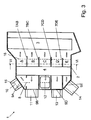
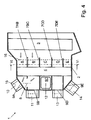
- a present four-zone automotive air conditioning system 1 has a multi-part air guide housing 2 made of plastic, in which an evaporator 3 and a heater 4 are arranged for temperature control of the vehicle interior to be supplied air.
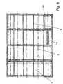
- a two-part by the middle partition centrally arranged Warmweg 5, in Fig. 5 framed with a dash-dot line, and to the right and left of each of which a cold path 6, in Fig. 5 each framed with a dashed line provided.
- the air coming from a fan (not shown) is passed through the evaporator 3 and then via the Warmweg 5 by the heater 4 or via one of the cold passages 6 past the heater 4.
- the air flow is in this case behind the evaporator 3 on each side of the means Partition wall divided into five partial air flows A, B, C, D, E, ie in a total of ten partial air flows, for which in the flow direction, in this case horizontally arranged and parallel walls 7AB, 7BC, 7CD and 7DE are arranged in the air guide housing 1, which something start spaced behind the evaporator 3, run through the heater 4 and laterally past the same, are continued behind the heater 4 and end at Beer.sgepitende.
- the design of the air guide housing 1 is as out Fig. 1 can be seen, essentially mirror-image for the driver and passenger side, so that in the following only one side reference is made.
- the partial air flow A is passed over a flap-controlled opening 9A obliquely upwards into the defrost air duct 10.
- the partial air flow B is guided via a flap-controlled opening 9B in an approximately horizontal direction in a ventilation air duct 11, which leads to the center and side nozzle.
- the partial air flow C is guided via a flap-controlled opening 9C in approximately horizontal direction laterally out of the air guide housing 1 out into a ventilation air duct 12, which leads to the front footwell.
- the partial air flow D is passed via a flap-controlled opening 9D in an approximately horizontal direction in a ventilation air duct 13, which leads to the rear ventilation.
- the partial air flow E is guided via a flap-controlled opening 9E obliquely down into a ventilation air duct 14, which leads to the rear footwell.
- the regulation takes place by means of shut-off valves 15 arranged in the region of the openings 9A, 9B, 9C, 9D and 9E.
- Fig. 6 Bottom right is a flap position indicated, which shows a guide of the entire passenger side, the rear footwell to be supplied partial air flow E through the heater 4, ie the rear passenger side footwell supplied air is "100% warm".
- the temperature flaps can be designed such that two flap surfaces arranged at right angles are rigidly connected to one another.
- a temperature flap for each partial air flow or two in their movement coupled (mechanically or otherwise) temperature flaps can be provided.
- a mixed mode front and rear area
- all the temperature flaps 16 are half open.
- the air of all partial air streams A, B, C, D, E is evenly distributed to the heater 4 and the bypass to the heater, wherein the hot and cold air of each air stream then mixed in the corresponding mixing chamber 17 before passing through the respective opening in the corresponding air duct passes.
- the flap 8 in the wall 7AB is presently closed, as in the present case, the butterfly valve 15 to defrost air duct 10.
- the flap 8 is open in this operating state, so that the partial air flow A is not blocked, but the partial air flow B. is admixed and is supplied via the center and side nozzles to the vehicle interior.
- each separate partial air flows A / B and C and E and D are provided within individual zones (ie front driver side, front passenger side, rear driver side and rear passenger side) can be very easily a temperature stratification of the air by appropriate control of the temperature flap positions to reach.
- the temperature of the partial air flow B (and A), which serves for ventilation of the front area set lower than the temperature of the partial air flow C, which is guided to the front foot space, and for the rear area is set by adjusting the temperature flaps 16, the temperature of the partial air flow E, which serves to ventilate the rear area, lower than the temperature of the partial air flow D, which is guided to the rear footwell.
- the walls (corresponding to the wall 7AB of the first embodiment) and the outer dimensions of the air duct housing in the corresponding area are modified accordingly in that the cold path is optimized for defrost operation, ie the wall in Kaltweg down and the wall in Warmweg is offset upwards, and side / top of the air duct housing the partial air flow A in Kaltweg a larger area and the partial air flow B in Warmweg a smaller area than in the first embodiment is available.
- the free cross sections of a corresponding partial air channel through the heater and the cross sections in the bypass are of different sizes.
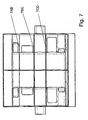
- the in Fig. 7 eliminates the wall 7DE for the partial air flows D and E, which are fed to the rear area (ventilation and footwell), so that in the rear area no temperature stratification is possible.
- the same function can also be produced by coupling the temperature flaps of the two partial air streams D and E with one another in accordance with the embodiment described above are, ie that automatically the same temperature flap position and thus the same temperature of the air serving the ventilation and the footwell to be supplied air is provided.
- the coupling can be done in the simplest embodiment by a rigidly connected, one-piece design of the temperature flaps, wherein the flap surfaces are arranged at a predetermined angle to each other, in particular at an angle of about 90 °.
- the individual walls 7AB (with or without flap 8), 7BC, 7CD and 7DE can - depending on the variant of the air conditioner - be modularly assembled, according to the simplest embodiment of the entire vehicle only one climate zone is provided (ie it is missing the component completely) , And according to the embodiment described in the embodiment described above (ie, the partition between the driver and passenger side with all walls 7AB-7DE are present) four climate zones in the vehicle are present, with an additional for each climate zone independent temperature stratification, including the possibility of cross-flow Partial air flows A and B is provided to improve the Defrost s and the acceleration of the cooling in the front area.
Landscapes
- Physics & Mathematics (AREA)
- Thermal Sciences (AREA)
- Engineering & Computer Science (AREA)
- Mechanical Engineering (AREA)
- Air-Conditioning For Vehicles (AREA)
- Duct Arrangements (AREA)
Applications Claiming Priority (1)
| Application Number | Priority Date | Filing Date | Title |
|---|---|---|---|
| DE102007031251A DE102007031251A1 (de) | 2007-07-04 | 2007-07-04 | Klimaanlage |
Publications (3)
| Publication Number | Publication Date |
|---|---|
| EP2011676A2 true EP2011676A2 (fr) | 2009-01-07 |
| EP2011676A3 EP2011676A3 (fr) | 2009-05-20 |
| EP2011676B1 EP2011676B1 (fr) | 2012-02-01 |
Family
ID=39683551
Family Applications (1)
| Application Number | Title | Priority Date | Filing Date |
|---|---|---|---|
| EP20080011671 Ceased EP2011676B1 (fr) | 2007-07-04 | 2008-06-27 | Climatiseur |
Country Status (2)
| Country | Link |
|---|---|
| EP (1) | EP2011676B1 (fr) |
| DE (1) | DE102007031251A1 (fr) |
Cited By (1)
| Publication number | Priority date | Publication date | Assignee | Title |
|---|---|---|---|---|
| CN116265271A (zh) * | 2021-12-17 | 2023-06-20 | 翰昂汽车零部件有限公司 | 机动车辆空气调节系统和用于操作机动车辆空气调节系统的方法 |
Families Citing this family (1)
| Publication number | Priority date | Publication date | Assignee | Title |
|---|---|---|---|---|
| DE102011080214A1 (de) * | 2011-08-01 | 2013-02-07 | Behr Gmbh & Co. Kg | Heiz- oder Klimaanlage, insbesondere für ein Kraftfahrzeug |
Citations (1)
| Publication number | Priority date | Publication date | Assignee | Title |
|---|---|---|---|---|
| DE102005029773A1 (de) | 2004-06-24 | 2006-01-12 | Behr Gmbh & Co. Kg | Klimaanlage, insbesondere Kraftfahrzeug-Klimaanlage |
Family Cites Families (10)
| Publication number | Priority date | Publication date | Assignee | Title |
|---|---|---|---|---|
| JPS587486B2 (ja) * | 1978-10-06 | 1983-02-10 | 三菱自動車工業株式会社 | 車両用空気調和装置 |
| JPS5863510A (ja) * | 1981-10-09 | 1983-04-15 | Nippon Denso Co Ltd | 自動車用空調装置 |
| JPS63312223A (ja) * | 1987-06-15 | 1988-12-20 | Nissan Motor Co Ltd | 車両用空調装置のヒ−タユニット構造 |
| DE19724644B4 (de) * | 1996-06-13 | 2006-07-20 | Denso Corp., Kariya | Klimaanlage für ein Fahrzeug |
| JP4134479B2 (ja) * | 1999-04-28 | 2008-08-20 | 株式会社デンソー | 車両用空調装置 |
| DE19955616C1 (de) * | 1999-11-19 | 2000-11-02 | Daimler Chrysler Ag | Klimaanlage für Fahrzeuge |
| KR100601835B1 (ko) * | 1999-12-30 | 2006-07-19 | 한라공조주식회사 | 자동차용 공기조화장치 |
| DE10016433B4 (de) * | 2000-04-01 | 2010-12-09 | Behr Gmbh & Co. Kg | Klimaanlage für ein Kraftfahrzeug |
| DE10225469C1 (de) * | 2002-06-08 | 2003-07-10 | Daimler Chrysler Ag | Heizungs- und/oder Klimaanlage |
| EP2015948B1 (fr) * | 2006-04-28 | 2016-08-10 | MAHLE Behr GmbH & Co. KG | Installation de climatisation pour vehicule automobile |
-
2007
- 2007-07-04 DE DE102007031251A patent/DE102007031251A1/de not_active Withdrawn
-
2008
- 2008-06-27 EP EP20080011671 patent/EP2011676B1/fr not_active Ceased
Patent Citations (1)
| Publication number | Priority date | Publication date | Assignee | Title |
|---|---|---|---|---|
| DE102005029773A1 (de) | 2004-06-24 | 2006-01-12 | Behr Gmbh & Co. Kg | Klimaanlage, insbesondere Kraftfahrzeug-Klimaanlage |
Cited By (1)
| Publication number | Priority date | Publication date | Assignee | Title |
|---|---|---|---|---|
| CN116265271A (zh) * | 2021-12-17 | 2023-06-20 | 翰昂汽车零部件有限公司 | 机动车辆空气调节系统和用于操作机动车辆空气调节系统的方法 |
Also Published As
| Publication number | Publication date |
|---|---|
| EP2011676A3 (fr) | 2009-05-20 |
| DE102007031251A1 (de) | 2009-01-08 |
| EP2011676B1 (fr) | 2012-02-01 |
Similar Documents
| Publication | Publication Date | Title |
|---|---|---|
| EP1902876B1 (fr) | Boîtier de distribution d'air, en particulier pour une climatisation de véhicule, le boîtier comprenant une vanne de distribution et un procédé de contrôle d'une telle vanne de distribution | |
| DE102015110559B4 (de) | Luftverteilungssystem für die dritte und/oder vierte Zone eines Drei- oder Vierzonen-Kraftfahrzeugklimagerätes | |
| EP2011675B1 (fr) | Climatiseur | |
| EP2015948B1 (fr) | Installation de climatisation pour vehicule automobile | |
| EP2048010B1 (fr) | Agencement de climatisation de véhicule automobile | |
| EP2011676B1 (fr) | Climatiseur | |
| EP1531068B1 (fr) | Installation de climatisation pour véhicule | |
| EP2048009B1 (fr) | Agencement de climatisation de véhicule automobile | |
| DE102004056813B4 (de) | Mehrzonen-Klimaanlage | |
| DE102018113175B4 (de) | Heck-Klimagerät für ein Fahrzeug | |
| EP1761405B1 (fr) | Climatiseur, en particulier climatiseur de vehicule automobile | |
| EP2088011B1 (fr) | Agencement de boîtier pour un système de climatisation de véhicule | |
| DE19756166B4 (de) | Luftkanal für eine Heizungs- oder Klimaanlage eines Kraftfahrzeuges sowie damit ausgerüstete Heizungs- oder Klimaanlage | |
| EP1972473B1 (fr) | Climatisation pour un véhicule automobile | |
| EP1792761B1 (fr) | Installation des volets | |
| DE102006012400B4 (de) | Heiz- und Lüftungsanlage für ein Fahrzeug mit einem der Mischklappe nachgeschaltetenKaltluftbypass | |
| EP1741581B1 (fr) | Appareil de ventilation, chauffage et climatisation pour l'arrière | |
| EP1738941A1 (fr) | Dispositif de climatisation pour véhicule | |
| DE102018121512B4 (de) | Klimagerät für ein Kraftfahrzeug | |
| EP1407903A1 (fr) | Dispositif de distribution d'air pour un appareil de chauffage et/ou climatisation de véhicule automobile | |
| EP2100759B1 (fr) | Cloison pour des systemes de climatisation de véhicules automobiles | |
| EP2133223B1 (fr) | Climatisation pour un véhicule automobile | |
| EP1555147B1 (fr) | Dispositif de climatisation pour véhicule | |
| DE102005051518A1 (de) | Kraftfahrzeug-Klimaanlage | |
| DE102019131470A1 (de) | Heizungs-, Lüftungs- und/oder Klimaanlage für ein Kraftfahrzeug |
Legal Events
| Date | Code | Title | Description |
|---|---|---|---|
| PUAI | Public reference made under article 153(3) epc to a published international application that has entered the european phase |
Free format text: ORIGINAL CODE: 0009012 |
|
| AK | Designated contracting states |
Kind code of ref document: A2 Designated state(s): AT BE BG CH CY CZ DE DK EE ES FI FR GB GR HR HU IE IS IT LI LT LU LV MC MT NL NO PL PT RO SE SI SK TR |
|
| AX | Request for extension of the european patent |
Extension state: AL BA MK RS |
|
| PUAL | Search report despatched |
Free format text: ORIGINAL CODE: 0009013 |
|
| AK | Designated contracting states |
Kind code of ref document: A3 Designated state(s): AT BE BG CH CY CZ DE DK EE ES FI FR GB GR HR HU IE IS IT LI LT LU LV MC MT NL NO PL PT RO SE SI SK TR |
|
| AX | Request for extension of the european patent |
Extension state: AL BA MK RS |
|
| 17P | Request for examination filed |
Effective date: 20091120 |
|
| 17Q | First examination report despatched |
Effective date: 20100105 |
|
| AKX | Designation fees paid |
Designated state(s): DE FR |
|
| GRAP | Despatch of communication of intention to grant a patent |
Free format text: ORIGINAL CODE: EPIDOSNIGR1 |
|
| RIN1 | Information on inventor provided before grant (corrected) |
Inventor name: KRAFT, THOMAS Inventor name: DIEKSANDER, WOLFGANG |
|
| GRAS | Grant fee paid |
Free format text: ORIGINAL CODE: EPIDOSNIGR3 |
|
| GRAA | (expected) grant |
Free format text: ORIGINAL CODE: 0009210 |
|
| AK | Designated contracting states |
Kind code of ref document: B1 Designated state(s): DE FR |
|
| REG | Reference to a national code |
Ref country code: DE Ref legal event code: R096 Ref document number: 502008006239 Country of ref document: DE Effective date: 20120329 |
|
| PLBE | No opposition filed within time limit |
Free format text: ORIGINAL CODE: 0009261 |
|
| STAA | Information on the status of an ep patent application or granted ep patent |
Free format text: STATUS: NO OPPOSITION FILED WITHIN TIME LIMIT |
|
| 26N | No opposition filed |
Effective date: 20121105 |
|
| REG | Reference to a national code |
Ref country code: DE Ref legal event code: R097 Ref document number: 502008006239 Country of ref document: DE Effective date: 20121105 |
|
| REG | Reference to a national code |
Ref country code: DE Ref legal event code: R082 Ref document number: 502008006239 Country of ref document: DE Representative=s name: GRAUEL, ANDREAS, DIPL.-PHYS. DR. RER. NAT., DE |
|
| REG | Reference to a national code |
Ref country code: DE Ref legal event code: R082 Ref document number: 502008006239 Country of ref document: DE Representative=s name: GRAUEL, ANDREAS, DIPL.-PHYS. DR. RER. NAT., DE Effective date: 20150317 Ref country code: DE Ref legal event code: R081 Ref document number: 502008006239 Country of ref document: DE Owner name: MAHLE INTERNATIONAL GMBH, DE Free format text: FORMER OWNER: BEHR GMBH & CO. KG, 70469 STUTTGART, DE Effective date: 20150317 |
|
| REG | Reference to a national code |
Ref country code: FR Ref legal event code: PLFP Year of fee payment: 9 |
|
| REG | Reference to a national code |
Ref country code: FR Ref legal event code: PLFP Year of fee payment: 10 |
|
| REG | Reference to a national code |
Ref country code: FR Ref legal event code: PLFP Year of fee payment: 11 |
|
| PGFP | Annual fee paid to national office [announced via postgrant information from national office to epo] |
Ref country code: DE Payment date: 20190822 Year of fee payment: 12 |
|
| PGFP | Annual fee paid to national office [announced via postgrant information from national office to epo] |
Ref country code: FR Payment date: 20200620 Year of fee payment: 13 |
|
| REG | Reference to a national code |
Ref country code: DE Ref legal event code: R119 Ref document number: 502008006239 Country of ref document: DE |
|
| PG25 | Lapsed in a contracting state [announced via postgrant information from national office to epo] |
Ref country code: DE Free format text: LAPSE BECAUSE OF NON-PAYMENT OF DUE FEES Effective date: 20210101 |
|
| PG25 | Lapsed in a contracting state [announced via postgrant information from national office to epo] |
Ref country code: FR Free format text: LAPSE BECAUSE OF NON-PAYMENT OF DUE FEES Effective date: 20210630 |