EP2011680B1 - Fahrzeugrolltor - Google Patents
Fahrzeugrolltor Download PDFInfo
- Publication number
- EP2011680B1 EP2011680B1 EP20080104387 EP08104387A EP2011680B1 EP 2011680 B1 EP2011680 B1 EP 2011680B1 EP 20080104387 EP20080104387 EP 20080104387 EP 08104387 A EP08104387 A EP 08104387A EP 2011680 B1 EP2011680 B1 EP 2011680B1
- Authority
- EP
- European Patent Office
- Prior art keywords
- lamellae
- vehicle door
- rolling vehicle
- door according
- slats
- Prior art date
- Legal status (The legal status is an assumption and is not a legal conclusion. Google has not performed a legal analysis and makes no representation as to the accuracy of the status listed.)
- Ceased
Links
- 238000005096 rolling process Methods 0.000 title claims description 16
- 241000446313 Lamella Species 0.000 claims description 4
- 238000006073 displacement reaction Methods 0.000 claims description 4
- 238000007789 sealing Methods 0.000 claims description 4
- 239000000463 material Substances 0.000 claims description 3
- 239000007787 solid Substances 0.000 claims description 3
- 230000002093 peripheral effect Effects 0.000 claims 3
- 229920003023 plastic Polymers 0.000 description 5
- 230000000694 effects Effects 0.000 description 3
- 230000000284 resting effect Effects 0.000 description 2
- XAGFODPZIPBFFR-UHFFFAOYSA-N aluminium Chemical compound [Al] XAGFODPZIPBFFR-UHFFFAOYSA-N 0.000 description 1
- 229910052782 aluminium Inorganic materials 0.000 description 1
- 230000007613 environmental effect Effects 0.000 description 1
- 238000001125 extrusion Methods 0.000 description 1
- 229920002457 flexible plastic Polymers 0.000 description 1
- 239000011120 plywood Substances 0.000 description 1
Images

Classifications
-
- B—PERFORMING OPERATIONS; TRANSPORTING
- B60—VEHICLES IN GENERAL
- B60J—WINDOWS, WINDSCREENS, NON-FIXED ROOFS, DOORS, OR SIMILAR DEVICES FOR VEHICLES; REMOVABLE EXTERNAL PROTECTIVE COVERINGS SPECIALLY ADAPTED FOR VEHICLES
- B60J5/00—Doors
- B60J5/04—Doors arranged at the vehicle sides
- B60J5/06—Doors arranged at the vehicle sides slidable; foldable
- B60J5/08—Doors arranged at the vehicle sides slidable; foldable of roller-blind type made of rigid elements
-
- B—PERFORMING OPERATIONS; TRANSPORTING
- B60—VEHICLES IN GENERAL
- B60J—WINDOWS, WINDSCREENS, NON-FIXED ROOFS, DOORS, OR SIMILAR DEVICES FOR VEHICLES; REMOVABLE EXTERNAL PROTECTIVE COVERINGS SPECIALLY ADAPTED FOR VEHICLES
- B60J5/00—Doors
- B60J5/10—Doors arranged at the vehicle rear
- B60J5/12—Doors arranged at the vehicle rear slidable; foldable
- B60J5/14—Doors arranged at the vehicle rear slidable; foldable of roller-blind type made of rigid elements
-
- E—FIXED CONSTRUCTIONS
- E05—LOCKS; KEYS; WINDOW OR DOOR FITTINGS; SAFES
- E05D—HINGES OR SUSPENSION DEVICES FOR DOORS, WINDOWS OR WINGS
- E05D15/00—Suspension arrangements for wings
- E05D15/16—Suspension arrangements for wings for wings sliding vertically more or less in their own plane
- E05D15/24—Suspension arrangements for wings for wings sliding vertically more or less in their own plane consisting of parts connected at their edges
- E05D15/242—Hinge connections between the parts
-
- E—FIXED CONSTRUCTIONS
- E05—LOCKS; KEYS; WINDOW OR DOOR FITTINGS; SAFES
- E05D—HINGES OR SUSPENSION DEVICES FOR DOORS, WINDOWS OR WINGS
- E05D1/00—Pinless hinges; Substitutes for hinges
- E05D1/02—Pinless hinges; Substitutes for hinges made of one piece
-
- E—FIXED CONSTRUCTIONS
- E05—LOCKS; KEYS; WINDOW OR DOOR FITTINGS; SAFES
- E05Y—INDEXING SCHEME ASSOCIATED WITH SUBCLASSES E05D AND E05F, RELATING TO CONSTRUCTION ELEMENTS, ELECTRIC CONTROL, POWER SUPPLY, POWER SIGNAL OR TRANSMISSION, USER INTERFACES, MOUNTING OR COUPLING, DETAILS, ACCESSORIES, AUXILIARY OPERATIONS NOT OTHERWISE PROVIDED FOR, APPLICATION THEREOF
- E05Y2900/00—Application of doors, windows, wings or fittings thereof
- E05Y2900/10—Application of doors, windows, wings or fittings thereof for buildings or parts thereof
- E05Y2900/106—Application of doors, windows, wings or fittings thereof for buildings or parts thereof for garages
Definitions
- the invention relates to a vehicle rolling door with a plate-shaped filling element, which consists of lamellae whose mutually facing, transversely to the direction of extending edge regions are connected by flexible, over the entire width of the filling element extending profile strands articulated.
- the vehicle rolling door in question is preferably used for releasing and closing the rear-side loading opening of a box-like vehicle body.
- the rails are attached.
- the slats are guided by laterally outward in offset to the two end faces of the slats stationary guide rollers which engage in the rails.
- the guide rollers are freely rotatably mounted on bearing bolts, which are inserted into bearing pin receptacles of the filling element. If the loading opening is released for loading or unloading, consequently, the filling element is pushed under the ceiling.
- the width of the filling element is adapted to the width of the structure of the vehicle. The number of lamellae forming the filling element depends on the height of the vehicle body and the height of the individual lamellae.
- the slats are made of plywood or hollow profiles and made of a suitable plastic or aluminum.
- the connections of the edge regions of the slats running transversely to the displacement direction can be made by hinges or the edge region of the slats are profiled in such a way that they engage in one another in a form-fitting manner.
- From the generic DE 198 28 186 A1 is a joint device known, which is designed in particular for roller shutter or trapdoor elements.
- the individual slats are formed as hollow profiles and designed so that the slats are connected to each other via connecting elements, and which are arranged within the hollow profiles.
- These fasteners are made of a very flexible plastic. At least in the end areas, these connecting elements are thickened tubular.
- a sectional door or a ceiling sectional door is known in which the slats are connected by hinges.
- the lamellae are provided on one side with grooves, engage in the webs of the slats. In these grooves legs of the hinge parts are inserted from the side. Also in this embodiment, the disadvantages already mentioned apply with regard to the use of hinges.
- the invention has for its object to design a vehicle rolling door of the type described in more detail that can be used cost-effective lamellae, and that the articulated connections are structurally simple design and to assemble in a very short time and a very good seal is made.
- the cross sections of the profile strands are T-shaped, that the transversely to the direction of the filling element surfaces of the lamellae are smooth surface at least on the outside and are spaced from each other, that the middle webs of the profile strands facing each other Surfaces of two adjacent lamellae are, and that the webs of the profile strands standing on both sides of the middle webs at right angles to it lie sealingly against the outer surfaces of the lamellas and are fixed by spaced-apart clamping devices.
- the flexible profile strands are designed so that the joints between the slats are covered. As a result, a sealing effect is achieved, so that the cargo space of a vehicle is protected against environmental influences. Since the profile strands are also flexible, the mobility of the slats when moving the filling element is secured.
- the two slats connecting safety device is structurally simple and installed in a very short time or, if necessary, to dismantle.
- the transverse to the displacement direction webs of the lamella are smooth surface at least on the outside and are at a distance to each other, and that in each case a leg of the profile strands facing between the each other lying surfaces of the fins, and these webs are also flexible, they can be designed so that they are a little under tension when the vehicle rolling door is in the closed position. As a result, the sealing effect is increased. If the slats are in the arcuate region of the rails, they can be further deformed according to the movement of the slats.
- the profile strands on the outer sides facing away from the lamellae have groove-like recesses which terminate at equal distances from the lateral edges.
- each securing device for two adjacent slats is formed from spaced-apart clamping devices.
- each clamping device includes two profile sections, one of which is fixed by means of mechanical fasteners to the edge region of the associated blade.
- a mechanical connecting element comes in a preferred embodiment, at least one screw with a nut into consideration.
- the profile sections are designed so that they lie without gaps, at least at the lateral edge regions of the profile strands resting against the lamellae. These strips contacting the profile sections can also be under tension.
- the profile sections are formed as angle profile sections. Furthermore, these angle profile sections are unequal, with the shorter legs are perpendicular to the slats.
- the clamping devices are based on the width of the roller door and go over the entire width of the slat.
- a receptacle for a bearing pin is laterally attached to the clamping devices, in which then the guided in the running rail roller is freely rotatably mounted.
- the securing devices are inaccessible in the closed position of the rolling door, it is provided that these are arranged on the loading space side of the filling element.
- the individual fins are inexpensive, it is provided that these are made of plastic profiles, in particular of solid plastic profiles with smooth outer surfaces.
- the filling element 10 consists of a plurality of fins 11, which are connected in an articulated manner in still further explained manner.
- the fins 11 are made of solid plastic profiles with smooth outer surfaces.
- two adjacent slats 11 are pivotally connected to each other via spaced clamping devices 12 and flexible profile strands 15.
- the clamping devices 12 form safety devices.
- the smooth surface of the surfaces of the slats 11 shows in particular the FIG. 3 , Furthermore, this figure shows that two adjacent lamellae 11 are spaced apart. In this gap protrudes a web 14 of a cross-sectionally T-shaped profile strand 15 into it. This web 14 is the middle bridge.
- the other two sections of the web extend on both sides of the central web 14 and lie close to the surfaces of the slats 11.
- the profile strand 15 is made of a flexible material, preferably made of plastic or rubber. In the central region, the web resting against the lamellae 11 has a groove-like recess 16.
- each clamping device consists of two angle section sections 17, 18 with non-uniform cross sections.
- the shorter legs are perpendicular to the slats 11.
- the facing surfaces of the two angle sections 16, 18 are spaced from each other.
- Each angle profile section 17, 18 is secured in the illustrated embodiment by at least one screw-nut connection 19, 20 on the associated blade 11.
- an angle profile section 21 is fixed in the illustrated embodiment, still by means of the screw-nut connection 20, to which a bearing bushing 22 is attached.
- this angle section 21 and the bearing bush 22 are only provided on the lateral clamping devices 12 to insert a bolt therein firmly on the free end of a run in the track rail roller is freely rotatably mounted.
- the invention is not limited to the illustrated embodiment. It is essential that there is a gap between the slats 11, in which the web 14 of a profile section 15 engages, wherein the webs lying on both sides of the web 14 bear sealingly against the surfaces of two adjacent slats 11.
Landscapes
- Engineering & Computer Science (AREA)
- Mechanical Engineering (AREA)
- Seal Device For Vehicle (AREA)
- Extensible Doors And Revolving Doors (AREA)
- Vehicle Interior And Exterior Ornaments, Soundproofing, And Insulation (AREA)
Description
- Die Erfindung betrifft ein Fahrzeugrolltor mit einem plattenförmigen Füllungselement, welches aus Lamellen besteht, deren einander zugewandte, quer zur Verschieberichtung verlaufende Randbereiche durch flexible, sich über die gesamte Breite des Füllungselementes erstreckende Profilstränge gelenkig miteinander verbunden sind.
- Das in Rede stehende Fahrzeugrolltor wird in bevorzugter Weise zur Freigabe und zum Verschließen der heckseitigen Ladeöffnung eines kofferartigen Fahrzeugaufbaus verwendet. An den heckseitigen Endbereichen der beiden Seitenwände des Kofferaufbaus sowie an der Decke sind die Laufschienen befestigt. Dazu sind die Lamellen durch seitlich nach außen im Versatz zu den beiden Stirnflächen der Lamellen stehende Führungsrollen geführt, die in die Laufschienen eingreifen. Die Führungsrollen sind auf Lagerbolzen frei drehbar gelagert, die in Lagerbolzenaufnahmen des Füllungselementes eingesetzt sind. Wenn die Ladeöffnung zum Be- oder Entladen freigegeben wird, wird demzufolge das Füllungselement unter die Decke geschoben. Die Breite des Füllungselementes ist an die Breite des Aufbaus des Fahrzeuges angepasst. Die Anzahl der das Füllungselement bildenden Lamellen richtet sich nach der Höhe des Fahrzeugaufbaus und der Höhe der einzelnen Lamellen.
- Bei den bislang bekannten Fahrzeugrolltoren sind die Lamellen aus Plywood oder als Hohlprofile ausgebildet und aus einem geeigneten Kunststoff oder aus Aluminium gefertigt. Die Verbindungen der quer zur Verschieberichtung verlaufenden Randbereiche der Lamellen können durch Scharniere erfolgen oder die Randbereich der Lamellen sind so profiliert, dass sie formschlüssig ineinander greifen.
- Die in Rede stehenden Fahrzeugrolltore haben sich in der Praxis außerordentlich bewährt. Es wird jedoch die Verbindung der einzelnen Lamellen mittels Scharnieren als zu aufwendig angesehen, da die Montagezeit relativ hoch ist. Sofern die Randbereiche der Lamellen profiliert sind, sind aufwendige Werkzeuge notwendig, so dass der Preis der Lamellen entsprechend hoch ist.
- Aus der gattungsgemäßen
DE 198 28 186 A1 ist eine Gelenkeinrichtung bekannt, die insbesondere für Rollladen- oder Falltürelemente ausgelegt ist. Die einzelnen Lamellen sind als Hohlprofile ausgebildet und so ausgelegt, dass die Lamellen über Verbindungselemente miteinander verbunden sind, und die innerhalb der Hohlprofile angeordnet sind. Diese Verbindungselemente bestehen aus einem äußerst flexiblen Kunststoff. Zumindest in den Endbereichen sind diese Verbindungselemente schlauchförmig verdickt. - Die Dichtwirkung dieser Verbindungselemente ist zwar gegeben, doch werden sie beim Öffnen und Schließen eines Rolltores beim Umlenken extrem stark gedehnt. Außerdem muss zum Auswechseln der Verbindungselemente das plattenförmige Füllungselement komplett aus den Führungsschienen herausgenommen werden.
- Aus der
US 3,570,579 ist ein aus Lamellen gebildetes plattenförmiges Füllungselement bekannt, bei dem die Randbereiche der Lamellen hakenförmig gestaltet sind. Zwei angrenzende Lamellen sind über ein entsprechend gestaltetes Scharnier miteinander gelenkig verbunden. Das Scharnier erstreckt sich über die gesamte Breite des Füllungselementes. Bei dieser Ausführung treten die eingangs erwähnten Nachteile hinsichtlich der Verwendung von Scharnieren auf. - Aus der
DE 92 11 848 U1 ist ein Sektionaltor oder ein Deckengliedertor bekannt, bei dem die Lamellen über Scharniere verbunden sind. Die Lamellen sind an einer Seite mit Nuten versehen, in die Stege der Lamellen eingreifen. In diese Nuten werden Schenkel der Scharnierteile von der Seite her eingesteckt. Auch bei dieser Ausführung gelten die bereits aufgeführten Nachteile hinsichtlich der Verwendung von Scharnieren. - Der Erfindung liegt die Aufgabe zugrunde, ein Fahrzeugrolltor der eingangs näher beschriebenen Art so zu gestalten, dass kostengünstig zu beziehende Lamellen verwendet werden können, und dass die gelenkigen Verbindungen konstruktiv einfach ausgebildet und in kürzester Zeit zu montieren sind und eine sehr gute Dichtigkeit hergestellt ist.
- Die gestellte Aufgabe wird dadurch gelöst, dass die Querschnitte der Profilstränge T-förmig ausgebildet sind, dass die quer zur Verschieberichtung des Füllungselementes stehenden Flächen der Lamellen wenigstens außenseitig glattflächig sind und in Abständen zueinander stehen, dass die mittleren Stege der Profilstränge zwischen den einander zugewandt liegenden Flächen von zwei angrenzenden Lamellen liegen, und dass die beidseitig der mittleren Stege rechtwinklig dazu stehenden Stege der Profilstränge dichtend an den Außenflächen der Lamellen anliegen und durch im Abstand zueinander angeordnete Klemmvorrichtungen festgelegt sind.
- Die flexiblen Profilstränge sind so ausgelegt, dass die zwischen den Lamellen liegenden Fugen abgedeckt werden. Dadurch wird eine Dichtwirkung erzielt, so dass der Laderaum eines Fahrzeuges gegen Umwelteinflüsse geschützt ist. Da die Profilstränge außerdem flexibel sind, ist die Beweglichkeit der Lamellen beim Verschieben des Füllungselementes gesichert. Die jeweils zwei Lamellen verbindende Sicherungsvorrichtung ist konstruktiv einfach aufgebaut und in kürzester Zeit zu montieren bzw. im Bedarfsfall auch zu demontieren.
- Da zumindest die quer zur Verschieberichtung stehenden Stege der Lamellen wenigstens an der Außenseite glattflächig sind und im Abstand zueinander stehen, und dass jeweils ein Schenkel der Profilstränge zwischen den einander zugewandt liegenden Flächen der Lamellen liegt, und diese Stege ebenfalls flexibel sind, können sie so ausgelegt sein, dass sie ein klein wenig unter Spannung stehen, wenn sich das Fahrzeugrolltor in der Schließlage befindet. Dadurch wird die Dichtwirkung noch erhöht. Wenn sich die Lamellen im bogenförmigen Bereich der Laufschienen befinden, können sie sich entsprechend der Bewegung der Lamellen noch zusätzlich verformen.
- Da die Profilstränge in den Querschnitten T-förmig ausgebildet sind, greift dann der Mittelsteg in den Spalt zwischen zwei angrenzenden Lamellen ein. Die rechtwinklig dazu stehenden Teilabschnitte jedes Steges liegen dann ebenfalls dichtend an den Randbereichen der Lamellen an. Ein solches Profil wird im Extrusionsverfahren hergestellt und ist demzufolge recht kostengünstig.
- Es ist ferner noch vorgesehen, das die Profilstränge an den äußeren, den Lamellen abgewandten Seiten nutartige Einziehungen aufweisen, die in gleichen Abständen zu den seitlichen Kanten enden.
- In konstruktiv einfacher Weise ist jede Sicherungsvorrichtung für zwei angrenzende Lamellen aus im Abstand zueinander angeordneten Klemmvorrichtungen gebildet.
- Es ist ferner noch vorgesehen, dass jede Klemmvorrichtung zwei Profilabschnitte beinhaltet, von denen jeweils einer mittels mechanischer Verbindungselemente an den Randbereich der zugehörigen Lamelle festgelegt ist. Als mechanisches Verbindungselement kommt in bevorzugter Ausführung wenigstens eine Schraube mit einer Mutter in Betracht. Die Profilabschnitte sind so ausgelegt, dass sie zumindest an den seitlichen Randbereichen der an den Lamellen anliegenden Profilstränge spaltfrei anliegen. Auch können diese die Profilabschnitte kontaktierenden Streifen unter einer Spannung stehen.
- In der einfachsten Ausführung ist vorgesehen, dass die Profilabschnitte als Winkelprofilabschnitte ausgebildet sind. Ferner sind diese Winkelprofilabschnitte ungleichschenklig, wobei die kürzeren Schenkel senkrecht zu den Lamellen stehen. Die Klemmvorrichtungen richten sich nach der Breite des Rolltores und gehen über die gesamte Breite der Lamelle.
- Zusätzlich wird an den Klemmvorrichtungen seitlich eine Aufnahme für einen Lagerbolzen angebracht, in dem dann die in der Laufschiene geführte Laufrolle frei drehbar gelagert ist.
- Damit die Sicherungsvorrichtungen in der Schließlage des Rolltores unzugänglich sind, ist vorgesehen, dass diese laderaumseitig an dem Füllungselement angeordnet sind.
- Damit die einzelnen Lamellen kostengünstig sind, ist vorgesehen, dass diese aus Kunststoffprofilen, insbesondere aus massiven Kunststoffprofilen mit glatten Außenflächen gebildet sind.
- Anhand der beiliegenden Zeichnungen wird die Erfindung noch näher erläutert.
- Es zeigen:
- Figur 1
- eine Teilansicht eines Rolltores mit Blick auf die Außenseite in der Schließlage
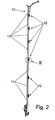
- Figur 2
- eine seitliche Ansicht und
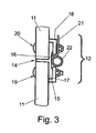
- Figur 3
- eine Einzelheit III in der
Figur 2 in vergrößerter Darstellung. - Aus Gründen einer vereinfachten Darstellung sind in den
Figuren 1 und2 nur die Füllungselemente 10 des erfindungsgemäßen Fahrzeugrolltores dargestellt. Die seitlichen Lagerbolzen, die darauf frei drehbar gelagerten Laufrollen und die Laufschienen sind nicht dargestellt. Das Füllungselement 10 besteht aus mehreren Lamellen 11, die in noch näher erläuterter Weise gelenkig miteinander verbunden sind. Die Lamellen 11 sind aus massiven Kunststoffprofilen mit glatten Außenflächen gefertigt. - Wie in den
Figuren 1 und2 dargestellt, sind zwei angrenzende Lamellen 11 über im Abstand zueinander angeordnete Klemmvorrichtungen 12 sowie flexible Profilstränge 15 gelenkig miteinander verbunden. Die Klemmvorrichtungen 12 bilden Sicherungsvorrichtungen. Die Glattflächigkeit der Flächen der Lamellen 11 zeigt insbesondere dieFigur 3 . Ferner zeigt diese Figur, dass zwei angrenzende Lamellen 11 im Abstand zueinander stehen. In diesen Spalt ragt ein Steg 14 eines im Querschnitt T-förmigen Profilstranges 15 hinein. Dieser Steg 14 ist der mittlere Steg. Die beiden anderen Abschnitte des Steges erstrecken sich beidseitig des mittleren Steges 14 und liegen dicht an den Flächen der Lamellen 11 an. Der Profilstrang 15 ist aus einem flexiblen Material, vorzugsweise aus Kunststoff oder Gummi gefertigt. Im mittleren Bereich hat der an den Lamellen 11 anliegende Steg eine nutartige Einziehung 16. - Wie die
Figur 3 zeigt, besteht jede Klemmvorrichtung aus zwei Winkelprofilabschnitten 17, 18 mit ungleichmäßigen Querschnitten. Dabei stehen die kürzeren Schenkel rechtwinklig zu den Lamellen 11. Die einander zugewandten Flächen der beiden Winkelprofilabschnitte 16, 18 stehen im Abstand zueinander. Jeder Winkelprofilabschnitt 17, 18 ist im dargestellten Ausführungsbeispiel durch wenigstens eine Schrauben-Mutter-Verbindung 19, 20 an der zugeordneten Lamelle 11 befestigt. - Am oberen Rand der jeweils unteren Lamelle 11 ist im dargestellten Ausführungsbeispiel noch mittels der Schrauben-Mutter-Verbindung 20 ein Winkelprofilabschnitt 21 befestigt, an dem eine Lagerbuchse 22 angesetzt ist. Dieser Winkelprofilabschnitt 21 und die Lagerbuchse 22 sind jedoch nur an den seitlichen Klemmvorrichtungen 12 vorgesehen, um einen Bolzen darin fest einzusetzen auf dessen freien Endbereich eine in der Laufschiene geführte Laufrolle frei drehbar gelagert ist.
- Die Erfindung ist nicht auf das dargestellte Ausführungsbeispiel beschränkt. Wesentlich ist, dass zwischen den Lamellen 11 ein Spalt liegt, in den der Steg 14 eines Profilabschnittes 15 eingreift, wobei die beidseitig des Steges 14 liegenden Stege dichtend an den Flächen von zwei angrenzenden Lamellen 11 anliegen.
Claims (7)
- Fahrzeugrolltor mit einem plattenförmigen Füllungselement (10), welches aus Lamellen (11) besteht, deren einander zugewandte, quer zur Verschieberichtung verlaufende Randbereiche durch von jeweils zwei angrenzenden Lamellen, sich über die gesamte Breite des Füllungselementes (10) erstreckende, flexible Profilstränge (15) gelenkig miteinander verbunden sind, dadurch gekennzeichnet, dass die Querschnitte der Profilstränge (15) T-förmig ausgebildet sind, dass die quer zur Verschieberichtung des Füllungselementes (10) stehenden Flächen der Lamellen (11) wenigstens außenseitig glattflächig sind und im Abstand zueinander stehen, dass die mittleren Stege (14) der T-förmigen Profilstränge (15) zwischen den einander zugewandt liegenden Flächen von zwei angrenzenden Lamellen (11) liegen, und dass die beidseitig der mittleren Stege (14) rechtwinklig dazu stehenden Stege der T-förmigen Profilstänge (15) dichtend an den Außenflächen von zwei amprenzenden Lamellen (11) anliegen und durch im Abstand zueinander angeordnete Klemmvorrichtungen (12) an den Lamellen (11) festgelegt sind.
- Fahrzeugrolltor nach Anspruch 1, dadurch gekennzeichnet, dass die Profilstränge (15) an den äußeren, den Lamellen (11) abgewandten Seiten nutartige Einziehungen (16) aufweisen.
- Fahrzeugrolltor nach Anspruch 1, dadurch gekennzeichnet, dass jede Klemmvorrichtung (12) zwei Profilabschnitte (17, 18) beinhaltet, von denen jeweils einer mittels mechanischer Verbindungselemente (19, 20) an den Randbereich der zugehörigen Lamelle (11) festgelegt ist.
- Fahrzeugrolltor nach Anspruch 3, dadurch gekennzeichnet, dass die Profilabschnitte als Winkelprofilabschnitte (17, 18) ausgebildet sind, wobei die Querschnitte ungleichschenklig sind und die kürzeren Schenkel rechtwinklig zu den Lamellen (11) stehen.
- Fahrzeugrolltor nach einem oder mehreren der vorstehenden Ansprüche, dadurch gekennzeichnet, dass zwei Klemmvorrichtungen (12) angrenzend an die seitlichen Stirnflächen der angrenzenden Lamellen (11) angeordnet sind, und dass an einem Profilabschnitt (21) eine Lagerbuchse (22) zur Aufnahme eines Lagerbolzens für eine Laufrolle festgelegt ist.
- Fahrzeugrolltor nach einem oder mehreren der vorstehenden Ansprüche, dadurch gekennzeichnet, dass die Sicherungsvorrichtungen laderaumseitig an dem Füllungselement (10) angeordnet sind.
- Fahrzeugrolltor nach einem oder mehreren der vorstehenden Ansprüche, dadurch gekennzeichnet, dass die Lamellen (11) aus Kunststoffprofilen mit glatten Außenflächen, vorzugsweise aus massiven Kunststoffprofilen gebildet sind.
Applications Claiming Priority (1)
| Application Number | Priority Date | Filing Date | Title |
|---|---|---|---|
| DE200720009449 DE202007009449U1 (de) | 2007-07-05 | 2007-07-05 | Fahrzeugrolltor |
Publications (3)
| Publication Number | Publication Date |
|---|---|
| EP2011680A2 EP2011680A2 (de) | 2009-01-07 |
| EP2011680A3 EP2011680A3 (de) | 2009-06-10 |
| EP2011680B1 true EP2011680B1 (de) | 2010-12-08 |
Family
ID=39720208
Family Applications (1)
| Application Number | Title | Priority Date | Filing Date |
|---|---|---|---|
| EP20080104387 Ceased EP2011680B1 (de) | 2007-07-05 | 2008-06-12 | Fahrzeugrolltor |
Country Status (2)
| Country | Link |
|---|---|
| EP (1) | EP2011680B1 (de) |
| DE (2) | DE202007009449U1 (de) |
Families Citing this family (1)
| Publication number | Priority date | Publication date | Assignee | Title |
|---|---|---|---|---|
| CN106476577B (zh) * | 2015-09-02 | 2019-11-22 | 北京宝沃汽车有限公司 | 汽车 |
Family Cites Families (8)
| Publication number | Priority date | Publication date | Assignee | Title |
|---|---|---|---|---|
| US3570579A (en) * | 1968-03-18 | 1971-03-16 | Nippon Musical Instruments Mfg | Sliding cover and housing device thereof |
| US4771816A (en) * | 1986-05-02 | 1988-09-20 | Whiting Roll-Up Door Mfg. Corp. | Plastic hinged and weatherstripped metal overhead door |
| DE9211848U1 (de) * | 1992-09-08 | 1992-11-19 | Braselmann, Herta, 2980 Norden | Sektionaltor oder Deckengliedertor |
| JP3543843B2 (ja) * | 1994-08-17 | 2004-07-21 | 日本フルハーフ株式会社 | ロ−ルアップドア−における上下パネルの結合部構造 |
| FR2765617B1 (fr) * | 1997-07-01 | 1999-09-17 | Gerard Grosse | Dispositif d'articulation notamment pour planches et rideau mouvant forme de planches assemblees au moyen de tels dispositifs |
| DE10230445A1 (de) * | 2002-07-06 | 2004-01-22 | Daimlerchrysler Ag | Tür für eine Karosserieöffnung von Kraftwagen |
| DE202005006531U1 (de) * | 2005-04-22 | 2005-06-23 | Wihag Fahrzeugbausysteme Gmbh | Fahrzeugrolltor |
| DE102005044173A1 (de) * | 2005-09-16 | 2007-03-22 | GM Global Technology Operations, Inc., Detroit | Heckklappenanordnung eines Fahrzeugs mit rolloartiger Heckklappe |
-
2007
- 2007-07-05 DE DE200720009449 patent/DE202007009449U1/de not_active Expired - Lifetime
-
2008
- 2008-06-12 DE DE200850001977 patent/DE502008001977D1/de active Active
- 2008-06-12 EP EP20080104387 patent/EP2011680B1/de not_active Ceased
Also Published As
| Publication number | Publication date |
|---|---|
| DE202007009449U1 (de) | 2008-11-13 |
| EP2011680A2 (de) | 2009-01-07 |
| DE502008001977D1 (de) | 2011-01-20 |
| EP2011680A3 (de) | 2009-06-10 |
Similar Documents
| Publication | Publication Date | Title |
|---|---|---|
| CH652442A5 (de) | Schiebetuer zum verschliessen einer wandoeffnung. | |
| DE2724962C2 (de) | Seilfensterheber | |
| DE69623626T2 (de) | Türsystem | |
| EP2317054B1 (de) | Schiebetür | |
| DE102007012153A1 (de) | Führungsschiene eines Türschließ-oder Türantriebssystems | |
| EP0681081A1 (de) | Abschlusselement für Wandöffnungen in Gebäuden od. dgl. | |
| DE202006017619U1 (de) | Rolltor | |
| EP1557519B1 (de) | Rahmenkörper aus einem hohlen, stranggepressten Kunststoffprofil für Fenster und Türen | |
| AT512327A1 (de) | Hebe/schiebetür | |
| EP2011680A2 (de) | Fahrzeugrolltor | |
| DE102017011293B4 (de) | Laufbahn, Fördereinrichtung und Verfahren zur Montage einer Laufbahn | |
| DE19828186A1 (de) | Gelenkeinrichtung, insbesondere für Rolladen- oder Falttürelemente, und Roll- oder Faltvorhang | |
| EP4345239A1 (de) | Rahmen zum einfassen mindestens einer scheibe und vorrichtung umfassend den rahmen und eine zarge | |
| EP0671536B1 (de) | Rolladen-Profil, insbesondere für Garagen- oder Rolltore | |
| DE10115096C1 (de) | Toranlage mit einem entlang mindestens eines ortsfesten Rollenbocks geführten Tragprofil | |
| EP3342973B1 (de) | Schwenk- und/oder schiebetüranlage | |
| WO2005090734A1 (de) | Vorrichtung zum verschluss und/oder zum schutz von bauwerksöffnungen | |
| EP3299534B1 (de) | Dachfenster | |
| DE19705550C2 (de) | Elektrischer Garagentorantrieb | |
| DE4447139A1 (de) | Tor mit einem vertikal bewegbaren Torblatt und einer Fangklinkeneinrichtung | |
| EP1714815B1 (de) | Fahrzeugrolltor | |
| DE202012011998U1 (de) | Schiebetüren- oder -fensteranordnung mit einem Zargenteil und darin verschiebbaren Tür- oder Fenster-Flügeln | |
| DE1936929C3 (de) | Fenster, Tür o.dgl | |
| DE19828267A1 (de) | Fenster- oder Türbeschlag | |
| DE2645671A1 (de) | Deckengliedertor |
Legal Events
| Date | Code | Title | Description |
|---|---|---|---|
| PUAI | Public reference made under article 153(3) epc to a published international application that has entered the european phase |
Free format text: ORIGINAL CODE: 0009012 |
|
| AK | Designated contracting states |
Kind code of ref document: A2 Designated state(s): AT BE BG CH CY CZ DE DK EE ES FI FR GB GR HR HU IE IS IT LI LT LU LV MC MT NL NO PL PT RO SE SI SK TR |
|
| AX | Request for extension of the european patent |
Extension state: AL BA MK RS |
|
| PUAL | Search report despatched |
Free format text: ORIGINAL CODE: 0009013 |
|
| AK | Designated contracting states |
Kind code of ref document: A3 Designated state(s): AT BE BG CH CY CZ DE DK EE ES FI FR GB GR HR HU IE IS IT LI LT LU LV MC MT NL NO PL PT RO SE SI SK TR |
|
| AX | Request for extension of the european patent |
Extension state: AL BA MK RS |
|
| RIC1 | Information provided on ipc code assigned before grant |
Ipc: B60J 5/08 20060101ALI20090506BHEP Ipc: B60J 5/14 20060101AFI20090506BHEP Ipc: E06B 9/58 20060101ALI20090506BHEP |
|
| 17P | Request for examination filed |
Effective date: 20091207 |
|
| AKX | Designation fees paid |
Designated state(s): DE FR GB |
|
| 17Q | First examination report despatched |
Effective date: 20100121 |
|
| GRAP | Despatch of communication of intention to grant a patent |
Free format text: ORIGINAL CODE: EPIDOSNIGR1 |
|
| GRAS | Grant fee paid |
Free format text: ORIGINAL CODE: EPIDOSNIGR3 |
|
| GRAA | (expected) grant |
Free format text: ORIGINAL CODE: 0009210 |
|
| AK | Designated contracting states |
Kind code of ref document: B1 Designated state(s): DE FR GB |
|
| REG | Reference to a national code |
Ref country code: GB Ref legal event code: FG4D Free format text: NOT ENGLISH |
|
| REF | Corresponds to: |
Ref document number: 502008001977 Country of ref document: DE Date of ref document: 20110120 Kind code of ref document: P |
|
| PLBE | No opposition filed within time limit |
Free format text: ORIGINAL CODE: 0009261 |
|
| STAA | Information on the status of an ep patent application or granted ep patent |
Free format text: STATUS: NO OPPOSITION FILED WITHIN TIME LIMIT |
|
| 26N | No opposition filed |
Effective date: 20110909 |
|
| REG | Reference to a national code |
Ref country code: DE Ref legal event code: R097 Ref document number: 502008001977 Country of ref document: DE Effective date: 20110909 |
|
| REG | Reference to a national code |
Ref country code: FR Ref legal event code: PLFP Year of fee payment: 9 |
|
| REG | Reference to a national code |
Ref country code: FR Ref legal event code: PLFP Year of fee payment: 10 |
|
| REG | Reference to a national code |
Ref country code: FR Ref legal event code: PLFP Year of fee payment: 11 |
|
| PGFP | Annual fee paid to national office [announced via postgrant information from national office to epo] |
Ref country code: FR Payment date: 20190503 Year of fee payment: 12 |
|
| PGFP | Annual fee paid to national office [announced via postgrant information from national office to epo] |
Ref country code: DE Payment date: 20190627 Year of fee payment: 12 Ref country code: GB Payment date: 20190503 Year of fee payment: 12 |
|
| REG | Reference to a national code |
Ref country code: DE Ref legal event code: R119 Ref document number: 502008001977 Country of ref document: DE |
|
| GBPC | Gb: european patent ceased through non-payment of renewal fee |
Effective date: 20200612 |
|
| PG25 | Lapsed in a contracting state [announced via postgrant information from national office to epo] |
Ref country code: GB Free format text: LAPSE BECAUSE OF NON-PAYMENT OF DUE FEES Effective date: 20200612 Ref country code: FR Free format text: LAPSE BECAUSE OF NON-PAYMENT OF DUE FEES Effective date: 20200630 |
|
| PG25 | Lapsed in a contracting state [announced via postgrant information from national office to epo] |
Ref country code: DE Free format text: LAPSE BECAUSE OF NON-PAYMENT OF DUE FEES Effective date: 20210101 |