EP2011920A1 - Ensemble excentrique à régulation de vitesse - Google Patents
Ensemble excentrique à régulation de vitesse Download PDFInfo
- Publication number
- EP2011920A1 EP2011920A1 EP08015166A EP08015166A EP2011920A1 EP 2011920 A1 EP2011920 A1 EP 2011920A1 EP 08015166 A EP08015166 A EP 08015166A EP 08015166 A EP08015166 A EP 08015166A EP 2011920 A1 EP2011920 A1 EP 2011920A1
- Authority
- EP
- European Patent Office
- Prior art keywords
- counterweight
- eccentric
- axis
- fastener
- tubular section
- Prior art date
- Legal status (The legal status is an assumption and is not a legal conclusion. Google has not performed a legal analysis and makes no representation as to the accuracy of the status listed.)
- Granted
Links
- 230000005484 gravity Effects 0.000 claims description 20
- 238000005461 lubrication Methods 0.000 claims description 2
- 239000000463 material Substances 0.000 claims description 2
- 230000000694 effects Effects 0.000 description 4
- 230000003247 decreasing effect Effects 0.000 description 3
- 239000012530 fluid Substances 0.000 description 3
- 230000006835 compression Effects 0.000 description 2
- 238000007906 compression Methods 0.000 description 2
- 238000007789 sealing Methods 0.000 description 2
- 230000000712 assembly Effects 0.000 description 1
- 238000000429 assembly Methods 0.000 description 1
- 230000007423 decrease Effects 0.000 description 1
- 239000013536 elastomeric material Substances 0.000 description 1
- 238000009434 installation Methods 0.000 description 1
- 239000000314 lubricant Substances 0.000 description 1
- 230000001681 protective effect Effects 0.000 description 1
- 230000003068 static effect Effects 0.000 description 1
- 238000003466 welding Methods 0.000 description 1
Images


Classifications
-
- E—FIXED CONSTRUCTIONS
- E01—CONSTRUCTION OF ROADS, RAILWAYS, OR BRIDGES
- E01C—CONSTRUCTION OF, OR SURFACES FOR, ROADS, SPORTS GROUNDS, OR THE LIKE; MACHINES OR AUXILIARY TOOLS FOR CONSTRUCTION OR REPAIR
- E01C19/00—Machines, tools or auxiliary devices for preparing or distributing paving materials, for working the placed materials, or for forming, consolidating, or finishing the paving
- E01C19/22—Machines, tools or auxiliary devices for preparing or distributing paving materials, for working the placed materials, or for forming, consolidating, or finishing the paving for consolidating or finishing laid-down unset materials
- E01C19/23—Rollers therefor; Such rollers usable also for compacting soil
- E01C19/28—Vibrated rollers or rollers subjected to impacts, e.g. hammering blows
- E01C19/286—Vibration or impact-imparting means; Arrangement, mounting or adjustment thereof; Construction or mounting of the rolling elements, transmission or drive thereto, e.g. to vibrator mounted inside the roll
-
- B—PERFORMING OPERATIONS; TRANSPORTING
- B06—GENERATING OR TRANSMITTING MECHANICAL VIBRATIONS IN GENERAL
- B06B—METHODS OR APPARATUS FOR GENERATING OR TRANSMITTING MECHANICAL VIBRATIONS OF INFRASONIC, SONIC, OR ULTRASONIC FREQUENCY, e.g. FOR PERFORMING MECHANICAL WORK IN GENERAL
- B06B1/00—Methods or apparatus for generating mechanical vibrations of infrasonic, sonic, or ultrasonic frequency
- B06B1/10—Methods or apparatus for generating mechanical vibrations of infrasonic, sonic, or ultrasonic frequency making use of mechanical energy
- B06B1/16—Methods or apparatus for generating mechanical vibrations of infrasonic, sonic, or ultrasonic frequency making use of mechanical energy operating with systems involving rotary unbalanced masses
- B06B1/161—Adjustable systems, i.e. where amplitude or direction of frequency of vibration can be varied
- B06B1/162—Making use of masses with adjustable amount of eccentricity
- B06B1/164—Making use of masses with adjustable amount of eccentricity the amount of eccentricity being automatically variable as a function of the running condition, e.g. speed, direction
Definitions
- This invention relates to vibration compacting machines, and more particularly to an eccentric assembly for a vibration compacting machine.
- an eccentric assembly for a vibration compacting machine, the eccentric assembly comprising a substantially closed tubular section having at least one sealable through bore and being rotatable about an axis; an eccentric weight coupled within the tubular section and having a centre of gravity on a first side of the axis; a counterweight coupled within the tubular section and having a centre of gravity on a second, opposite side of the axis, the counterweight being moveable relative to the eccentric weight over a range between a first position and a second position; a fastener extending from the eccentric weight, through the counterweight and including a head member that is aligned with the through bore; a biasing member positioned about the fastener between the fastener head and the counterweight such that a biasing force biases the counterweight toward the first position, adjustment of the fastener through the through bore permitting adjustment of the biasing force; and a cap for sealingly closing the through bore.
- the eccentric assembly can generate vibrations that have a lower amplitude at high rotational speeds (i.e. frequencies). Reducing vibration amplitude at higher shaft speeds minimises wear to each of the load bearing components in the vibration compacting machine, resulting in an extended service life for the vibration compacting machine.
- the present eccentric assembly is easily and inexpensively manufactured, can be readily adapted to be used in existing vibration compacting machines and encases all critical moving components within a protective tubular section.
- the eccentric assembly includes a tubular section, an eccentric weight, and a counterweight.
- Fig. 1 illustrates a vibration compacting machine used in leveling paved or unpaved ground surfaces.
- the vibration compacting machine 8 includes a frame 12 and at least one drum assembly 14 mounted to one end of the frame 12 for rotation about a longitudinal axis 13.
- the opposite end of the frame 12 generally has a wheel assembly 11 or a second drum assembly (not shown) that, with drum assembly 14, supports the frame 12 for movement over the ground surface.
- An operator's station 9, including a steering wheel 10 or the like, is provided on the frame 12 for driving and operation of the compacting machine 8.
- the drum assembly 14 includes a drum 16 and an eccentric assembly 20 that is mounted for rotation relative to the drum 16.
- the eccentric assembly 20 rotates about an axis of rotation 21 that is substantially aligned with the longitudinal axis 13 of the drum assembly 14.
- the eccentric assembly 20 includes a moment of eccentricity such that rotation of the eccentric assembly 20 by a motor 15 creates vibrations that are transferred through the drum 16 to the ground.
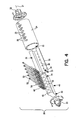
- the biasing members 60 are preferably compression springs, but other structures, for example, an elastomeric material or a semi-compressible fluid, may also be used. In the case of a fluid, the shoulder members 54 would provide a sealing fit to prevent leakage of such fluid.
- the eccentric weight 30 and counterweight 40 structure can easily be changed by detaching the eccentric weight 30 from the tubular section 24, for example, by removing securing screws, and securing a different eccentric weight 30 and counterweight 40 structure within the tubular section 24.
- Each fastener 50 has a head portion 52 which overlies a portion of the shoulder member 54 such that tightening of the fastener 50 compresses the biasing member 40 within the receiving portion 47 of the bore 46.
- the counterweight 40 is thereby biased toward a first position ( Fig. 5 ) wherein the counterweight first portion 42 is received fully in the eccentric weight cavity 34. Tightening or loosening of the fastener 50 controls the compression, and corresponding biasing force, of the biasing member 60.
- the counterweight 40 is moveable over a range between the first position ( Fig. 5 ) and a second position ( Fig. 6 ) wherein the convex surface 45 of the counterweight 40 is in contact with the inner surface 25 of the tubular section 24.
Landscapes
- Engineering & Computer Science (AREA)
- Mechanical Engineering (AREA)
- Architecture (AREA)
- Civil Engineering (AREA)
- Structural Engineering (AREA)
- Apparatuses For Generation Of Mechanical Vibrations (AREA)
- Road Paving Machines (AREA)
Applications Claiming Priority (2)
| Application Number | Priority Date | Filing Date | Title |
|---|---|---|---|
| US09/901,840 US6585450B2 (en) | 2001-07-10 | 2001-07-10 | Speed controlled eccentric assembly |
| EP02746961A EP1404923B1 (fr) | 2001-07-10 | 2002-07-10 | Ensemble excentrique a regulation de vitesse |
Related Parent Applications (2)
| Application Number | Title | Priority Date | Filing Date |
|---|---|---|---|
| EP02746961.8 Division | 2002-07-10 | ||
| EP02746961A Division EP1404923B1 (fr) | 2001-07-10 | 2002-07-10 | Ensemble excentrique a regulation de vitesse |
Publications (2)
| Publication Number | Publication Date |
|---|---|
| EP2011920A1 true EP2011920A1 (fr) | 2009-01-07 |
| EP2011920B1 EP2011920B1 (fr) | 2010-09-01 |
Family
ID=25414899
Family Applications (2)
| Application Number | Title | Priority Date | Filing Date |
|---|---|---|---|
| EP02746961A Expired - Lifetime EP1404923B1 (fr) | 2001-07-10 | 2002-07-10 | Ensemble excentrique a regulation de vitesse |
| EP08015166A Expired - Lifetime EP2011920B1 (fr) | 2001-07-10 | 2002-07-10 | Ensemble excentrique à régulation de vitesse |
Family Applications Before (1)
| Application Number | Title | Priority Date | Filing Date |
|---|---|---|---|
| EP02746961A Expired - Lifetime EP1404923B1 (fr) | 2001-07-10 | 2002-07-10 | Ensemble excentrique a regulation de vitesse |
Country Status (4)
| Country | Link |
|---|---|
| US (1) | US6585450B2 (fr) |
| EP (2) | EP1404923B1 (fr) |
| DE (2) | DE60237557D1 (fr) |
| WO (1) | WO2003006742A1 (fr) |
Families Citing this family (11)
| Publication number | Priority date | Publication date | Assignee | Title |
|---|---|---|---|---|
| SE525020C2 (sv) * | 2003-03-21 | 2004-11-09 | Metso Dynapac Ab | Ställdon för reglering av en vältvals excenteraxels excentermoment |
| US7066681B2 (en) * | 2004-11-17 | 2006-06-27 | M-B-W Inc. | Shaft assembly for a vibratory roller |
| ATE378793T1 (de) * | 2005-06-23 | 2007-11-15 | Akg Acoustics Gmbh | Methode zur modellierung eines mikrofons |
| US7588389B1 (en) * | 2006-12-19 | 2009-09-15 | Humphrey John L | Greensroller with variable vibration amplitude |
| US20110017482A1 (en) * | 2009-07-23 | 2011-01-27 | Keith Carl A | Roller Technology |
| US20110158745A1 (en) * | 2009-12-31 | 2011-06-30 | Caterpillar Paving Products Inc. | Vibratory system for a compactor |
| EP2989252A4 (fr) * | 2013-04-25 | 2017-01-11 | Volvo Construction Equipment AB | Ensemble permettant de faire vibrer un tambour de compactage d'une machine de compactage |
| WO2017114546A1 (fr) * | 2015-12-28 | 2017-07-06 | Volvo Construction Equipment Ab | Ensemble excentrique pour machine de compactage par vibration |
| US10024004B1 (en) | 2017-02-28 | 2018-07-17 | Caterpillar Paving Products Inc. | Variable eccentricity via sliding mechanism |
| CN108374307B (zh) * | 2018-03-16 | 2021-05-11 | 浙江路之友工程机械有限公司 | 一种压路机的冲击钢轮 |
| CN113665226B (zh) * | 2021-08-16 | 2022-07-12 | 清远南方制版科技有限公司 | 一种动平衡纠偏装置及应用动平衡纠偏装置的纠偏方法 |
Citations (4)
| Publication number | Priority date | Publication date | Assignee | Title |
|---|---|---|---|---|
| US3867073A (en) | 1972-09-20 | 1975-02-18 | Raygo Inc | Control for fluid motor |
| US4341126A (en) | 1977-02-25 | 1982-07-27 | Thomas Hubert E | Variable amplitude vibratory apparatus |
| US4367054A (en) * | 1981-02-24 | 1983-01-04 | The Koehring Company | Vibratory roller |
| DE10031617A1 (de) | 2000-06-29 | 2002-01-17 | Wacker Werke Kg | Vibrationserreger mit Amplitudenverstellung |
Family Cites Families (15)
| Publication number | Priority date | Publication date | Assignee | Title |
|---|---|---|---|---|
| US2481174A (en) | 1949-01-03 | 1949-09-06 | Jeffrey Mfg Co | Variable unbalanced weight mechanism for mechanical vibrating screens and the like |
| US2989869A (en) * | 1957-02-25 | 1961-06-27 | Continental Oil Co | Constant force variable speed vibrator |
| CH465935A (de) | 1967-10-27 | 1968-11-30 | Meyer Fa Rudolf | Vibrator mit Kurzschlussankermotor |
| DE2127433B2 (de) * | 1971-06-03 | 1973-05-30 | Grimmer, Klaus Jürgen, Dr Ing , 4720 Beckum | Unwuchterreger zum antrieb einer schwingrinne oder eines schwingsiebes |
| US3896677A (en) | 1974-01-18 | 1975-07-29 | Raygo Inc | Dual amplitude vibration generator |
| US4033193A (en) | 1974-03-04 | 1977-07-05 | International Combustion Australia Limited | Vibratory drive unit |
| US4176983A (en) | 1978-07-17 | 1979-12-04 | Ingersoll-Rand Company | Variable eccentric device |
| US4342523A (en) | 1981-02-24 | 1982-08-03 | Koehring Company | High-low force amplitude device |
| SE434550B (sv) * | 1983-01-26 | 1984-07-30 | Dynapac Maskin Ab | Anordning for lagring av stora exenterkrafter |
| US4550622A (en) | 1983-05-12 | 1985-11-05 | Ingersoll-Rand Company | Plural-amplitude vibration assembly |
| US4568218A (en) * | 1984-07-16 | 1986-02-04 | Wacker Corporation | Adjustably controllable centrifugal vibratory exciter |
| US4759659A (en) * | 1987-07-01 | 1988-07-26 | Fernand Copie | Variable vibrator system |
| US4749305A (en) * | 1987-08-31 | 1988-06-07 | Ingersoll-Rand Company | Eccentric-weight subassembly, and in combination with an earth compactor drum |
| US4830534A (en) | 1987-10-21 | 1989-05-16 | Hyster Company | Dual amplitude vibration generator for compaction apparatus |
| DE19529115A1 (de) * | 1995-08-08 | 1997-03-06 | Wacker Werke Kg | Vibrationsmechanismus, insbesondere zur Verwendung zur Verdichtung von Böden |
-
2001
- 2001-07-10 US US09/901,840 patent/US6585450B2/en not_active Expired - Lifetime
-
2002
- 2002-07-10 DE DE60237557T patent/DE60237557D1/de not_active Expired - Lifetime
- 2002-07-10 WO PCT/US2002/021815 patent/WO2003006742A1/fr not_active Ceased
- 2002-07-10 EP EP02746961A patent/EP1404923B1/fr not_active Expired - Lifetime
- 2002-07-10 DE DE60231713T patent/DE60231713D1/de not_active Expired - Lifetime
- 2002-07-10 EP EP08015166A patent/EP2011920B1/fr not_active Expired - Lifetime
Patent Citations (4)
| Publication number | Priority date | Publication date | Assignee | Title |
|---|---|---|---|---|
| US3867073A (en) | 1972-09-20 | 1975-02-18 | Raygo Inc | Control for fluid motor |
| US4341126A (en) | 1977-02-25 | 1982-07-27 | Thomas Hubert E | Variable amplitude vibratory apparatus |
| US4367054A (en) * | 1981-02-24 | 1983-01-04 | The Koehring Company | Vibratory roller |
| DE10031617A1 (de) | 2000-06-29 | 2002-01-17 | Wacker Werke Kg | Vibrationserreger mit Amplitudenverstellung |
Also Published As
| Publication number | Publication date |
|---|---|
| EP1404923A1 (fr) | 2004-04-07 |
| EP2011920B1 (fr) | 2010-09-01 |
| US20030012602A1 (en) | 2003-01-16 |
| DE60231713D1 (de) | 2009-05-07 |
| US6585450B2 (en) | 2003-07-01 |
| EP1404923B1 (fr) | 2009-03-25 |
| DE60237557D1 (de) | 2010-10-14 |
| WO2003006742A1 (fr) | 2003-01-23 |
Similar Documents
| Publication | Publication Date | Title |
|---|---|---|
| EP2011920B1 (fr) | Ensemble excentrique à régulation de vitesse | |
| US4753128A (en) | Robot with spring pivot balancing mechanism | |
| CA1197115A (fr) | Dispositif de maintien en tension d'une courroie ou chaine d'entrainement | |
| DE3590411C2 (de) | Riemenspannvorrichtung | |
| US9725855B2 (en) | Assembly for vibrating a compacting drum of a compacting machine | |
| US5409070A (en) | Coupling for rotary-vibratory drills | |
| US5702315A (en) | Autotensioner | |
| EP1358019B1 (fr) | Ensemble a poids excentriques en phase | |
| US4165466A (en) | Drive apparatus for vehicle mounted generator | |
| SE521863C2 (sv) | Länkhjul | |
| DE102010027205A1 (de) | Handwerkzeug | |
| CA2252906A1 (fr) | Systeme amortisseur a film comprime porte par un ressort suspendu pour paliers d'arbres | |
| US4609055A (en) | Vibrating plate | |
| CA1046820A (fr) | Compacteur automoteur a plaque a sens de marche reversible | |
| KR20010074865A (ko) | 전기 유변 유체/자기 유변 유체를 기초로하는 벨트 인장시스템용 진동 댐퍼 | |
| KR920004683B1 (ko) | 회전식 충격장치 | |
| DE10214384A1 (de) | Verbrennungsmotor eines handgeführten Arbeitsgerätes | |
| US20110013990A1 (en) | Device for producing vibrations | |
| DE2538577C2 (de) | Anordnung zur Dämpfung von Biegeschwingungen des Rotors von Maschinen mit einer Freiträgerwelle | |
| EP0090953B1 (fr) | Machine hydraulique à piston axial | |
| DE3521460A1 (de) | Unwuchtkegelbrecher | |
| US6725736B1 (en) | Rotatable eccentric arrangement | |
| US20020084113A1 (en) | Apparatus for counterbalancing weight | |
| US5000140A (en) | Isolated thrust pin for use with a rotating shaft | |
| EP0078808A1 (fr) | Dispositif vibrant pour compacteurs vibratoires |
Legal Events
| Date | Code | Title | Description |
|---|---|---|---|
| PUAI | Public reference made under article 153(3) epc to a published international application that has entered the european phase |
Free format text: ORIGINAL CODE: 0009012 |
|
| 17P | Request for examination filed |
Effective date: 20080828 |
|
| AC | Divisional application: reference to earlier application |
Ref document number: 1404923 Country of ref document: EP Kind code of ref document: P |
|
| AK | Designated contracting states |
Kind code of ref document: A1 Designated state(s): AT BE BG CH CY CZ DE DK EE ES FI FR GB GR IE IT LI LU MC NL PT SE SK TR |
|
| AX | Request for extension of the european patent |
Extension state: AL LT LV MK RO SI |
|
| RAP1 | Party data changed (applicant data changed or rights of an application transferred) |
Owner name: VOLVO CONSTRUCTION EQUIPMENT AB |
|
| 17Q | First examination report despatched |
Effective date: 20090710 |
|
| AKX | Designation fees paid |
Designated state(s): DE FR GB IT SE |
|
| GRAP | Despatch of communication of intention to grant a patent |
Free format text: ORIGINAL CODE: EPIDOSNIGR1 |
|
| GRAS | Grant fee paid |
Free format text: ORIGINAL CODE: EPIDOSNIGR3 |
|
| GRAA | (expected) grant |
Free format text: ORIGINAL CODE: 0009210 |
|
| AC | Divisional application: reference to earlier application |
Ref document number: 1404923 Country of ref document: EP Kind code of ref document: P |
|
| AK | Designated contracting states |
Kind code of ref document: B1 Designated state(s): DE FR GB IT SE |
|
| REG | Reference to a national code |
Ref country code: GB Ref legal event code: FG4D |
|
| REF | Corresponds to: |
Ref document number: 60237557 Country of ref document: DE Date of ref document: 20101014 Kind code of ref document: P |
|
| REG | Reference to a national code |
Ref country code: SE Ref legal event code: TRGR |
|
| PLBE | No opposition filed within time limit |
Free format text: ORIGINAL CODE: 0009261 |
|
| STAA | Information on the status of an ep patent application or granted ep patent |
Free format text: STATUS: NO OPPOSITION FILED WITHIN TIME LIMIT |
|
| 26N | No opposition filed |
Effective date: 20110606 |
|
| REG | Reference to a national code |
Ref country code: DE Ref legal event code: R097 Ref document number: 60237557 Country of ref document: DE Effective date: 20110606 |
|
| REG | Reference to a national code |
Ref country code: FR Ref legal event code: PLFP Year of fee payment: 15 |
|
| PGFP | Annual fee paid to national office [announced via postgrant information from national office to epo] |
Ref country code: IT Payment date: 20160712 Year of fee payment: 15 |
|
| PGFP | Annual fee paid to national office [announced via postgrant information from national office to epo] |
Ref country code: FR Payment date: 20160722 Year of fee payment: 15 |
|
| PGFP | Annual fee paid to national office [announced via postgrant information from national office to epo] |
Ref country code: GB Payment date: 20170728 Year of fee payment: 16 Ref country code: DE Payment date: 20170727 Year of fee payment: 16 |
|
| PGFP | Annual fee paid to national office [announced via postgrant information from national office to epo] |
Ref country code: SE Payment date: 20170710 Year of fee payment: 16 |
|
| REG | Reference to a national code |
Ref country code: FR Ref legal event code: ST Effective date: 20180330 |
|
| PG25 | Lapsed in a contracting state [announced via postgrant information from national office to epo] |
Ref country code: FR Free format text: LAPSE BECAUSE OF NON-PAYMENT OF DUE FEES Effective date: 20170731 |
|
| PG25 | Lapsed in a contracting state [announced via postgrant information from national office to epo] |
Ref country code: IT Free format text: LAPSE BECAUSE OF NON-PAYMENT OF DUE FEES Effective date: 20170710 |
|
| REG | Reference to a national code |
Ref country code: DE Ref legal event code: R119 Ref document number: 60237557 Country of ref document: DE |
|
| GBPC | Gb: european patent ceased through non-payment of renewal fee |
Effective date: 20180710 |
|
| PG25 | Lapsed in a contracting state [announced via postgrant information from national office to epo] |
Ref country code: DE Free format text: LAPSE BECAUSE OF NON-PAYMENT OF DUE FEES Effective date: 20190201 Ref country code: GB Free format text: LAPSE BECAUSE OF NON-PAYMENT OF DUE FEES Effective date: 20180710 |
|
| PG25 | Lapsed in a contracting state [announced via postgrant information from national office to epo] |
Ref country code: SE Free format text: LAPSE BECAUSE OF NON-PAYMENT OF DUE FEES Effective date: 20180711 |