EP2011961A2 - Outil - Google Patents
Outil Download PDFInfo
- Publication number
- EP2011961A2 EP2011961A2 EP08007080A EP08007080A EP2011961A2 EP 2011961 A2 EP2011961 A2 EP 2011961A2 EP 08007080 A EP08007080 A EP 08007080A EP 08007080 A EP08007080 A EP 08007080A EP 2011961 A2 EP2011961 A2 EP 2011961A2
- Authority
- EP
- European Patent Office
- Prior art keywords
- actuator
- tool according
- unit
- chisel
- bit
- Prior art date
- Legal status (The legal status is an assumption and is not a legal conclusion. Google has not performed a legal analysis and makes no representation as to the accuracy of the status listed.)
- Granted
Links
Images

Classifications
-
- E—FIXED CONSTRUCTIONS
- E21—EARTH OR ROCK DRILLING; MINING
- E21C—MINING OR QUARRYING
- E21C35/00—Details of, or accessories for, machines for slitting or completely freeing the mineral from the seam, not provided for in groups E21C25/00 - E21C33/00, E21C37/00 or E21C39/00
- E21C35/18—Mining picks; Holders therefor
- E21C35/19—Means for fixing picks or holders
-
- B—PERFORMING OPERATIONS; TRANSPORTING
- B25—HAND TOOLS; PORTABLE POWER-DRIVEN TOOLS; MANIPULATORS
- B25B—TOOLS OR BENCH DEVICES NOT OTHERWISE PROVIDED FOR, FOR FASTENING, CONNECTING, DISENGAGING, OR HOLDING
- B25B27/00—Hand tools, specially adapted for fitting together or separating parts or objects whether or not involving some deformation, not otherwise provided for
- B25B27/02—Hand tools, specially adapted for fitting together or separating parts or objects whether or not involving some deformation, not otherwise provided for for connecting objects by press fit or detaching same
-
- B—PERFORMING OPERATIONS; TRANSPORTING
- B25—HAND TOOLS; PORTABLE POWER-DRIVEN TOOLS; MANIPULATORS
- B25B—TOOLS OR BENCH DEVICES NOT OTHERWISE PROVIDED FOR, FOR FASTENING, CONNECTING, DISENGAGING, OR HOLDING
- B25B27/00—Hand tools, specially adapted for fitting together or separating parts or objects whether or not involving some deformation, not otherwise provided for
- B25B27/02—Hand tools, specially adapted for fitting together or separating parts or objects whether or not involving some deformation, not otherwise provided for for connecting objects by press fit or detaching same
- B25B27/06—Hand tools, specially adapted for fitting together or separating parts or objects whether or not involving some deformation, not otherwise provided for for connecting objects by press fit or detaching same inserting or withdrawing sleeves or bearing races
- B25B27/064—Hand tools, specially adapted for fitting together or separating parts or objects whether or not involving some deformation, not otherwise provided for for connecting objects by press fit or detaching same inserting or withdrawing sleeves or bearing races fluid driven
-
- E—FIXED CONSTRUCTIONS
- E21—EARTH OR ROCK DRILLING; MINING
- E21C—MINING OR QUARRYING
- E21C35/00—Details of, or accessories for, machines for slitting or completely freeing the mineral from the seam, not provided for in groups E21C25/00 - E21C33/00, E21C37/00 or E21C39/00
- E21C35/18—Mining picks; Holders therefor
- E21C35/188—Mining picks; Holders therefor characterised by adaptations to use an extraction tool
-
- E—FIXED CONSTRUCTIONS
- E21—EARTH OR ROCK DRILLING; MINING
- E21C—MINING OR QUARRYING
- E21C35/00—Details of, or accessories for, machines for slitting or completely freeing the mineral from the seam, not provided for in groups E21C25/00 - E21C33/00, E21C37/00 or E21C39/00
- E21C35/18—Mining picks; Holders therefor
- E21C35/19—Means for fixing picks or holders
- E21C35/197—Means for fixing picks or holders using sleeves, rings or the like, as main fixing elements
-
- B—PERFORMING OPERATIONS; TRANSPORTING
- B23—MACHINE TOOLS; METAL-WORKING NOT OTHERWISE PROVIDED FOR
- B23P—METAL-WORKING NOT OTHERWISE PROVIDED FOR; COMBINED OPERATIONS; UNIVERSAL MACHINE TOOLS
- B23P19/00—Machines for simply fitting together or separating metal parts or objects, or metal and non-metal parts, whether or not involving some deformation; Tools or devices therefor so far as not provided for in other classes
- B23P19/02—Machines for simply fitting together or separating metal parts or objects, or metal and non-metal parts, whether or not involving some deformation; Tools or devices therefor so far as not provided for in other classes for connecting objects by press fit or for detaching same
- B23P19/025—For detaching only
-
- Y—GENERAL TAGGING OF NEW TECHNOLOGICAL DEVELOPMENTS; GENERAL TAGGING OF CROSS-SECTIONAL TECHNOLOGIES SPANNING OVER SEVERAL SECTIONS OF THE IPC; TECHNICAL SUBJECTS COVERED BY FORMER USPC CROSS-REFERENCE ART COLLECTIONS [XRACs] AND DIGESTS
- Y10—TECHNICAL SUBJECTS COVERED BY FORMER USPC
- Y10T—TECHNICAL SUBJECTS COVERED BY FORMER US CLASSIFICATION
- Y10T29/00—Metal working
- Y10T29/49—Method of mechanical manufacture
- Y10T29/49718—Repairing
- Y10T29/49721—Repairing with disassembling
- Y10T29/4973—Replacing of defective part
-
- Y—GENERAL TAGGING OF NEW TECHNOLOGICAL DEVELOPMENTS; GENERAL TAGGING OF CROSS-SECTIONAL TECHNOLOGIES SPANNING OVER SEVERAL SECTIONS OF THE IPC; TECHNICAL SUBJECTS COVERED BY FORMER USPC CROSS-REFERENCE ART COLLECTIONS [XRACs] AND DIGESTS
- Y10—TECHNICAL SUBJECTS COVERED BY FORMER USPC
- Y10T—TECHNICAL SUBJECTS COVERED BY FORMER US CLASSIFICATION
- Y10T29/00—Metal working
- Y10T29/49—Method of mechanical manufacture
- Y10T29/49826—Assembling or joining
- Y10T29/49945—Assembling or joining by driven force fit
-
- Y—GENERAL TAGGING OF NEW TECHNOLOGICAL DEVELOPMENTS; GENERAL TAGGING OF CROSS-SECTIONAL TECHNOLOGIES SPANNING OVER SEVERAL SECTIONS OF THE IPC; TECHNICAL SUBJECTS COVERED BY FORMER USPC CROSS-REFERENCE ART COLLECTIONS [XRACs] AND DIGESTS
- Y10—TECHNICAL SUBJECTS COVERED BY FORMER USPC
- Y10T—TECHNICAL SUBJECTS COVERED BY FORMER US CLASSIFICATION
- Y10T29/00—Metal working
- Y10T29/53—Means to assemble or disassemble
- Y10T29/53683—Spreading parts apart or separating them from face to face engagement
-
- Y—GENERAL TAGGING OF NEW TECHNOLOGICAL DEVELOPMENTS; GENERAL TAGGING OF CROSS-SECTIONAL TECHNOLOGIES SPANNING OVER SEVERAL SECTIONS OF THE IPC; TECHNICAL SUBJECTS COVERED BY FORMER USPC CROSS-REFERENCE ART COLLECTIONS [XRACs] AND DIGESTS
- Y10—TECHNICAL SUBJECTS COVERED BY FORMER USPC
- Y10T—TECHNICAL SUBJECTS COVERED BY FORMER US CLASSIFICATION
- Y10T29/00—Metal working
- Y10T29/53—Means to assemble or disassemble
- Y10T29/53796—Puller or pusher means, contained force multiplying operator
-
- Y—GENERAL TAGGING OF NEW TECHNOLOGICAL DEVELOPMENTS; GENERAL TAGGING OF CROSS-SECTIONAL TECHNOLOGIES SPANNING OVER SEVERAL SECTIONS OF THE IPC; TECHNICAL SUBJECTS COVERED BY FORMER USPC CROSS-REFERENCE ART COLLECTIONS [XRACs] AND DIGESTS
- Y10—TECHNICAL SUBJECTS COVERED BY FORMER USPC
- Y10T—TECHNICAL SUBJECTS COVERED BY FORMER US CLASSIFICATION
- Y10T29/00—Metal working
- Y10T29/53—Means to assemble or disassemble
- Y10T29/53796—Puller or pusher means, contained force multiplying operator
- Y10T29/5383—Puller or pusher means, contained force multiplying operator having fluid operator
-
- Y—GENERAL TAGGING OF NEW TECHNOLOGICAL DEVELOPMENTS; GENERAL TAGGING OF CROSS-SECTIONAL TECHNOLOGIES SPANNING OVER SEVERAL SECTIONS OF THE IPC; TECHNICAL SUBJECTS COVERED BY FORMER USPC CROSS-REFERENCE ART COLLECTIONS [XRACs] AND DIGESTS
- Y10—TECHNICAL SUBJECTS COVERED BY FORMER USPC
- Y10T—TECHNICAL SUBJECTS COVERED BY FORMER US CLASSIFICATION
- Y10T29/00—Metal working
- Y10T29/53—Means to assemble or disassemble
- Y10T29/53909—Means comprising hand manipulatable tool
Definitions
- the invention relates to a tool for disassembling a bit on a bit holder with an actuator having a Abdrückabites, wherein the actuator is displaceable along a direction of travel.
- Such a tool is from the WO 97/23710 known.
- a pin-shaped Abdrückabêt is coupled to a handle by means of a hinge connection.
- the tool is used to disassemble a chisel inserted in a receiving bore of a chisel holder.
- the receiving bore is designed as a through hole, so that a chisel shank of the inserted bit is accessible from the rear.
- On the end of the chisel shaft a securing element is mounted, which is held in a groove of the receiving bore and thus holds the chisel in the chisel holder. If the bit to be replaced, for example, when reaching its wear limit, then the Abdenburgabêt is inserted through the rear opening in the mounting hole and brought to the free end of the drill collar to the plant.
- the handle can then be pivoted until it comes to rest on a support section. Now the handle can be adjusted relative to the Abdschreibabrough in the joint. The resulting leverage forces are introduced via the Abdschreibabêt such in the chisel, that the securing element caused by the fuse is released.
- a new, unworn bit can be attached to the location hole and driven in with a hammer. The change of a chisel is power consuming with the known arrangement and in confined spaces not feasible safely.
- the actuator is displaceable by means of an actuating unit, that the actuating unit has a Einziehabites which is spaced from the Abdrückabites and which is arranged transversely to the direction of the actuator, and that the actuator in the direction of travel by means of the actuator bidirectional power actuated is.
- the Abdrückabites is used for chisel dismantling, can be brought to the mounting position of the chisel in the mounting position.
- the actuator which adjusts the actuator bidirectional and thus in the assembly and disassembly directions.
- the actuator is power actuated by means of the actuator, for example via an electric or a hydraulic drive, so that the user's job when chisel change is greatly facilitated.
- the tool according to the invention can thus perform both the assembly and the dismantling work.
- the actuator between the Abdrückabites and the Einziehabites has a transversely to the direction of travel of the actuator accessible receiving portion.
- the chisel can be easily inserted with an adapted body contour into the receiving section.
- this body contour may have a circumferential groove on the shank of the bit, in which engages the actuator.
- the receiving portion transverse to the feed direction is less than or equal to the maximum cross section of the actuator in this direction, then the receiving portion does not project beyond the actuator transverse to the feed direction. This allows a compact design can be achieved. This has advantages, for example, when a chisel is to be mounted and dismounted through a receiving bore in which the chisel is held.
- the actuator is designed claw-like with the push-off section and the pull-in section, and that with the push-off section and the pull-in section a curved, in particular part-circular, Einlegeut is limited.
- the bit can be used for example with a cylindrical collar in the insertion.
- a variant of the invention provides that the actuating unit has a hydraulic unit with a hydraulic cylinder in which a piston is adjustable, and that the actuator is coupled via a piston rod to the piston.
- the hydraulic unit may have a reversing unit, which allows a bidirectional application of force to the piston.
- an embodiment of the invention provides that the hydraulic unit is coupled to an electric motor, that the electric motor is connected to an accumulator, and that the hydraulic unit, the electric motor and the accumulator are combined in a hand-operated unit.
- the tool can then be operated independently of external power supplies and thus easy to handle.
- the assembly and disassembly can be reliably carried out when a positive connection between the bit and the actuator is made.
- the setting unit has two support surfaces facing in opposite directions, which are directed in the direction of travel of the actuator.
- the actuating unit has two support parts which are arranged spaced apart in the direction of travel. With these support parts, the tool can then be supported on specially provided mating surfaces of the chisel holder, etc.
- the actuator should be movable in a defined starting position.
- an embodiment of the invention is characterized in that the actuating unit has an alignment section, on which the actuator is aligned in its retracted and / or extended end position.
- a rock excavation machine such as a surface miner, a road milling machine or the like, a tool unit mounted, in particular welded.
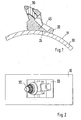
- the tool unit comprises a base part 20, which is placed with a concave abutment portion 24 and welded to the roll surface 11.
- the base part 20 has a tool holder 21 into which a chisel 30, in particular a round shank chisel, is inserted.
- the chisel 30 has a chisel head in the usual way and a chisel shaft 33 connected thereto.
- the chisel 30 carries in the region of its chisel shank 33, a clamping sleeve 35, as the Fig. 3 lets recognize.
- the clamping sleeve 35 engages with retaining elements 36 in a circumferential groove 34 of the drill shank 33 a. It is thus freely rotatable, but held captive in the axial direction.
- the bit holder 40 has a centering receptacle 41 around the chisel holder 42 encircling chamfering, which limits an insertion opening 43 for the bit 30.
- the bit holder 40 can be inserted into a bit holder receptacle 23 of the base part 20 and firmly connected to the base part 20, for example welded, (see welds 46 in FIG Fig. 4 ). In case of wear, the welds 46 can be separated and the bit holder 30 are replaced with a new unworn. Also conceivable is a tool design, in which the base part 20 and the bit holder 30 are combined in one piece as a structural unit (see FIG. 1 ).
- a tool can be used. This can be used both for mounting and for disassembly of the bit 30.
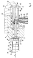
- the tool has an actuating unit 60, which surrounds a cylindrical interior 63.
- a piston 66 is guided linearly between two end positions.
- the piston 66 is sealed with respect to the cylinder wall bounding the interior by means of an O-ring.
- a piston rod 67 is coupled, which is led out through a closure insert 68 from the interior 63.
- the closure insert 68 is sealed inserted into the open side of the actuator 60.
- the piston rod 67 is also sealed against the closure insert 68, so that a pressure-tight interior 63 results.
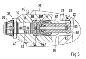
- the piston rod 67 carries at its free, the piston 66 remote from the end of an actuator 70.
- the actuator 70 is attached thereto with a pushed through a bore 71 of the actuator 70 clamping pin 72 thereto.
- the actuator 70 has a Einziehabonce 73 and a Abdrückabites 74. These are spaced from each other, so that there is a claw. The distance is selected so that the bit 30 can be inserted into the claw such that the retraction portion 73 engages in the groove 38.
- the actuator 60 has at its rear end a support member 61 which is formed by a widened contour.
- An end planar support surface 62 closes off the actuator 60 back, while on the opposite front, a support surface 69 is arranged.
- This support surface 69 is formed by a front-side support member 69.1, which has a lateral recess 69.2.
- a handle 50 is coupled to a battery-powered hydraulic unit 51. Since the power supply is integrated into the handle 50, an easily manageable tool results.
- the hydraulic unit 51 is connected via hydraulic lines 64.1 and 64.2 with the interior 63 in connection.
- the interior 63 and the hydraulic unit 51 are filled with a fluid, in particular hydraulic oil.
- the tool is inserted into the bulge 45.
- the tool is centered with the support members 61 and 69.1 on mating surfaces of the base member 20 and the chisel holder 40 so that it can be aligned.
- the support member 61 and the actuator 70 limits the insertion movement, wherein the actuator 70 acts against the cylindrical support member 39 of the bit 30.
- the support members 61 and 69.1 lead the tool perpendicular to the insertion movement.
- the hydraulic unit 51 can be activated.
- hydraulic oil is conveyed through the hydraulic line 64.2 and thereby the piston 66 is axially displaced in the direction of the bit 30.
- the flat ejection section 74 engages the free end of the bit 30.
- the chisel 30 is pushed out of the receiving bore 42 against the frictional force applied by the clamping sleeve 35.
- the actuator 60 is supported with its support surface 62 on the corresponding mating surface of the base part 20 from how Fig. 3 shows.
- the front-side support surface 69 is then released, which is characterized by the 3 mm-sized distance range.
- the push-out movement of the piston 66 is limited to the closure insert 68.
- the actuator 70 is so far extended from the bit holder 42 that the bit 30 is released and this can be removed.
- a chisel 30 can be used with its support member 39 in the formed between the Einziehabschnitt 73 and the Abd Wegabrough 74 groove portion of the actuator 70. It results in the Fig. 3 specified positioning.
- the hydraulic 51 can be reversed with a switching device 52, so that the hydraulic oil is conveyed via the hydraulic line 64.1 in the interior 63 and pumped out of the hydraulic line 64.2 from this.
- the piston 66 moves in the image plane according to Fig. 3 from left to right until he reaches the in Fig. 4 reached shown end position.
- the chisel 30 is retracted with the engaging on the support member 39 Einziehabites 73 in the bit holder 42.
- actuator 70 is shown in FIG Fig. 5 shown position in the circumferential direction non-rotatably aligned with a stop of the actuator 60 (alignment section 69.3).
Landscapes
- Engineering & Computer Science (AREA)
- Mining & Mineral Resources (AREA)
- Mechanical Engineering (AREA)
- Geology (AREA)
- General Life Sciences & Earth Sciences (AREA)
- Geochemistry & Mineralogy (AREA)
- Life Sciences & Earth Sciences (AREA)
- Percussive Tools And Related Accessories (AREA)
- Cutting Tools, Boring Holders, And Turrets (AREA)
- Portable Power Tools In General (AREA)
- Shearing Machines (AREA)
- Earth Drilling (AREA)
- Automatic Tool Replacement In Machine Tools (AREA)
Applications Claiming Priority (1)
| Application Number | Priority Date | Filing Date | Title |
|---|---|---|---|
| DE102007030640A DE102007030640B3 (de) | 2007-07-02 | 2007-07-02 | Werkzeug |
Publications (3)
| Publication Number | Publication Date |
|---|---|
| EP2011961A2 true EP2011961A2 (fr) | 2009-01-07 |
| EP2011961A3 EP2011961A3 (fr) | 2015-01-28 |
| EP2011961B1 EP2011961B1 (fr) | 2017-05-31 |
Family
ID=38542858
Family Applications (1)
| Application Number | Title | Priority Date | Filing Date |
|---|---|---|---|
| EP08007080.8A Active EP2011961B1 (fr) | 2007-07-02 | 2008-04-10 | Outil de coupe réglable |
Country Status (8)
| Country | Link |
|---|---|
| US (3) | US8099847B2 (fr) |
| EP (1) | EP2011961B1 (fr) |
| JP (1) | JP4904314B2 (fr) |
| CN (2) | CN101337345B (fr) |
| AU (1) | AU2008201921B2 (fr) |
| DE (2) | DE202007010047U1 (fr) |
| RU (1) | RU2470155C2 (fr) |
| ZA (1) | ZA200805688B (fr) |
Cited By (1)
| Publication number | Priority date | Publication date | Assignee | Title |
|---|---|---|---|---|
| USD688282S1 (en) | 2012-02-09 | 2013-08-20 | Frank Friedrich Lachmann | Tool |
Families Citing this family (27)
| Publication number | Priority date | Publication date | Assignee | Title |
|---|---|---|---|---|
| DE202007010047U1 (de) * | 2007-07-02 | 2007-09-27 | Wirtgen Gmbh | Werkzeug |
| DE102007030658A1 (de) * | 2007-07-02 | 2009-01-15 | Betek Bergbau- Und Hartmetalltechnik Karl-Heinz Simon Gmbh & Co. Kg | Schaftmeißel |
| DE102008025071A1 (de) | 2008-05-26 | 2009-12-03 | Wirtgen Gmbh | Werkzeug zur Demontage eines Meißels |
| US8214987B1 (en) * | 2008-10-14 | 2012-07-10 | Jefferson Science Associates, Llc | Remote vacuum or pressure sealing device and method for critical isolated systems |
| DE102009049780B4 (de) * | 2009-10-19 | 2016-02-18 | Betek Gmbh & Co. Kg | Meißel, insbesondere Rundschaftmeißel |
| WO2011101612A2 (fr) * | 2010-02-22 | 2011-08-25 | Minnovation Limited | Système d'extraction pour pic de haveuse |
| USD669505S1 (en) * | 2011-11-23 | 2012-10-23 | Wirtgen Gmbh | Chisel holder bar |
| USD677285S1 (en) * | 2011-11-23 | 2013-03-05 | Wirtgen Gmbh | Chisel holder bar |
| US8870297B2 (en) * | 2012-06-19 | 2014-10-28 | Caterpillar Inc. | Reclaiming drum having reversible kicker paddle |
| USD772315S1 (en) | 2013-04-11 | 2016-11-22 | Betek Gmbh & Co. Kg | Chisel |
| DE102013110676A1 (de) * | 2013-09-26 | 2015-03-26 | Betek Gmbh & Co. Kg | Meißel |
| DE102014104040A1 (de) | 2014-03-24 | 2015-09-24 | Betek Gmbh & Co. Kg | Meißel, insbesondere Rundschaftmeißel |
| US9512719B2 (en) * | 2015-01-20 | 2016-12-06 | Kennametal Inc. | Cutting tool holder extraction device |
| US10486293B2 (en) | 2015-12-17 | 2019-11-26 | Steven Gerard Verkley | Device for extracting cutting bit from holder |
| DE102016108808A1 (de) | 2016-05-12 | 2017-11-16 | Betek Gmbh & Co. Kg | Meißel mit einem Stützelement mit einem Zentrieransatz |
| EP3246514A1 (fr) * | 2016-05-20 | 2017-11-22 | Henri Wiertz | Élément de coupe pour un outil d'éjection de tambour de rouleau de fraisage |
| BR102017024641B1 (pt) * | 2016-11-18 | 2022-12-06 | Joy Global Surface Mining Inc | Sistema de ferramenta |
| CN107175458B (zh) * | 2017-07-21 | 2019-03-29 | 鞍钢集团矿业有限公司 | 合金铸球模具的加工修复方法 |
| DE102017130800A1 (de) | 2017-12-20 | 2019-06-27 | Wirtgen Gmbh | Werkzeug für die Montage eines Meißels an und/oder die Demontage eine Meißels von einem Meißelhaltersystem einer Fräsmaschine |
| US11203103B2 (en) | 2018-06-01 | 2021-12-21 | Caterpillar Paving Products Inc. | Rotor bit removal device |
| US11274423B2 (en) * | 2019-02-22 | 2022-03-15 | G. Dennis Gordon | Road grader blade teeth removal apparatus |
| US11208887B2 (en) * | 2019-08-23 | 2021-12-28 | Caterpillar Paving Products Inc. | Tool holder installation device and system |
| CN110842466B (zh) * | 2019-11-30 | 2020-11-27 | 中车大连机车车辆有限公司 | 一种机车转向架构架变形的修复工艺 |
| CN115592370A (zh) * | 2021-07-09 | 2023-01-13 | 三赢科技(深圳)有限公司(Cn) | 拆卸装置 |
| US12011852B2 (en) | 2022-02-21 | 2024-06-18 | Kennametal Inc. | Washers for Rotatable Cutting Tools |
| USD1015136S1 (en) | 2022-02-21 | 2024-02-20 | Kennametal Inc. | Washer for cutting tools |
| CN117532301B (zh) * | 2024-01-10 | 2024-03-22 | 太原理工大学 | 一种用于快速连接与拆卸矿用截齿的超声传递装置 |
Citations (6)
| Publication number | Priority date | Publication date | Assignee | Title |
|---|---|---|---|---|
| DE3026930A1 (de) | 1980-04-08 | 1981-10-15 | The Cincinnati Mine Machinery Co., Cincinnati, Ohio | Keilanordnung und zugeordnete mittel fuer befestigungsvorrichtungen, traeger und meissel und derenkombinationen fuer den bergbau, strassenbau und erdbewegungsmaschinen |
| DE3223761A1 (de) | 1982-06-25 | 1983-12-29 | Wolfgang 6603 Sulzbach Preinfalk | Abziehwerkzeug fuer schraemmeissel |
| DE8403441U1 (de) | 1984-02-07 | 1984-05-17 | Ruhrkohle Ag, 4300 Essen | Geraet zum wechseln von rundschaftmeisseln |
| DE4323669A1 (de) | 1993-07-15 | 1995-01-19 | Betek Bergbau & Hartmetall | Werkzeug |
| WO1997023710A1 (fr) | 1995-12-21 | 1997-07-03 | Tamrock Voest-Alpine Bergtechnik Gesellschaft Mbh | Systeme de burinage pour trepan a queue cylindrique |
| US6526641B1 (en) | 1999-11-01 | 2003-03-04 | Keystone Engineering & Manufacturing Company | Device for separating cutting bits from holders |
Family Cites Families (17)
| Publication number | Priority date | Publication date | Assignee | Title |
|---|---|---|---|---|
| SU1187975A1 (ru) * | 1983-08-26 | 1985-10-30 | Автокомбинат N 35 Управления Торгового Транспорта Главмосавтотранса | Устройство дл монтажа и демонтажа деталей |
| JPH0641078B2 (ja) * | 1986-03-12 | 1994-06-01 | 東芝機械株式会社 | 自動工具交換装置 |
| DE8625406U1 (de) * | 1986-09-23 | 1986-11-06 | Geisert Bergtechnik GmbH, 6601 Bübingen | Meißel eines Schneidkopfes einer Gewinnungsmaschine oder Vortriebmaschine |
| JPS63318234A (ja) * | 1988-05-16 | 1988-12-27 | Brother Ind Ltd | 工作機械 |
| RU2039643C1 (ru) * | 1992-01-10 | 1995-07-20 | Краснодарский научно-исследовательский институт "НИИМонтаж" | Переносной электрогидравлический инструмент для сборки, разборки, перемещения и других операций |
| DE4424534C2 (de) | 1994-07-12 | 1996-08-14 | Oehler Maschbau Gmbh | Werkzeug |
| DE4424537A1 (de) | 1994-07-12 | 1996-01-18 | Sick Optik Elektronik Erwin | Verfahren zum Betrieb eines Lichtgitters und Lichtgitter |
| US5761785A (en) * | 1995-06-30 | 1998-06-09 | Abb Flexible Automation, Inc. | Vacuum tool for installing valve spring retainer and keys |
| JP3894599B2 (ja) * | 1996-09-24 | 2007-03-22 | 森精機興産株式会社 | 工作機械の自動工具交換方法および自動工具交換装置を備えた工作機械 |
| US6131261A (en) * | 1998-06-30 | 2000-10-17 | Michlin; Steven Bruce | Arbor press extender device and method |
| US6122810A (en) * | 1999-08-30 | 2000-09-26 | Mcinnes; Robert P. | Valve core grasping apparatus |
| US6415487B1 (en) * | 2001-05-31 | 2002-07-09 | Dana Corporation | Service tool for removal of valve seal assembly |
| US6601277B1 (en) * | 2002-09-13 | 2003-08-05 | Richard C. Swanson | Puller tool for bolt seals and the like |
| DE10331970B4 (de) * | 2003-07-14 | 2008-01-31 | Wirtgen Gmbh | Baumaschine |
| JP2009006455A (ja) * | 2007-06-29 | 2009-01-15 | Komatsu Ntc Ltd | 工作機械 |
| DE202007010047U1 (de) * | 2007-07-02 | 2007-09-27 | Wirtgen Gmbh | Werkzeug |
| DE102007030658A1 (de) * | 2007-07-02 | 2009-01-15 | Betek Bergbau- Und Hartmetalltechnik Karl-Heinz Simon Gmbh & Co. Kg | Schaftmeißel |
-
2007
- 2007-07-02 DE DE202007010047U patent/DE202007010047U1/de not_active Expired - Lifetime
- 2007-07-02 DE DE102007030640A patent/DE102007030640B3/de active Active
-
2008
- 2008-04-10 EP EP08007080.8A patent/EP2011961B1/fr active Active
- 2008-05-01 AU AU2008201921A patent/AU2008201921B2/en active Active
- 2008-05-13 JP JP2008125535A patent/JP4904314B2/ja active Active
- 2008-06-30 ZA ZA200805688A patent/ZA200805688B/en unknown
- 2008-06-30 US US12/215,919 patent/US8099847B2/en active Active
- 2008-07-01 RU RU2008126783/03A patent/RU2470155C2/ru active
- 2008-07-01 CN CN200810126563XA patent/CN101337345B/zh active Active
- 2008-07-01 CN CNU2008201262088U patent/CN201304630Y/zh not_active Expired - Lifetime
-
2012
- 2012-01-11 US US13/348,211 patent/US9109444B2/en active Active
-
2015
- 2015-08-11 US US14/822,964 patent/US9765619B2/en active Active
Patent Citations (6)
| Publication number | Priority date | Publication date | Assignee | Title |
|---|---|---|---|---|
| DE3026930A1 (de) | 1980-04-08 | 1981-10-15 | The Cincinnati Mine Machinery Co., Cincinnati, Ohio | Keilanordnung und zugeordnete mittel fuer befestigungsvorrichtungen, traeger und meissel und derenkombinationen fuer den bergbau, strassenbau und erdbewegungsmaschinen |
| DE3223761A1 (de) | 1982-06-25 | 1983-12-29 | Wolfgang 6603 Sulzbach Preinfalk | Abziehwerkzeug fuer schraemmeissel |
| DE8403441U1 (de) | 1984-02-07 | 1984-05-17 | Ruhrkohle Ag, 4300 Essen | Geraet zum wechseln von rundschaftmeisseln |
| DE4323669A1 (de) | 1993-07-15 | 1995-01-19 | Betek Bergbau & Hartmetall | Werkzeug |
| WO1997023710A1 (fr) | 1995-12-21 | 1997-07-03 | Tamrock Voest-Alpine Bergtechnik Gesellschaft Mbh | Systeme de burinage pour trepan a queue cylindrique |
| US6526641B1 (en) | 1999-11-01 | 2003-03-04 | Keystone Engineering & Manufacturing Company | Device for separating cutting bits from holders |
Cited By (1)
| Publication number | Priority date | Publication date | Assignee | Title |
|---|---|---|---|---|
| USD688282S1 (en) | 2012-02-09 | 2013-08-20 | Frank Friedrich Lachmann | Tool |
Also Published As
| Publication number | Publication date |
|---|---|
| EP2011961B1 (fr) | 2017-05-31 |
| AU2008201921B2 (en) | 2010-11-04 |
| US20120174366A1 (en) | 2012-07-12 |
| RU2470155C2 (ru) | 2012-12-20 |
| US9109444B2 (en) | 2015-08-18 |
| CN101337345B (zh) | 2010-12-01 |
| DE102007030640B3 (de) | 2008-10-16 |
| US20090019679A1 (en) | 2009-01-22 |
| JP2009012165A (ja) | 2009-01-22 |
| CN201304630Y (zh) | 2009-09-09 |
| RU2008126783A (ru) | 2010-01-10 |
| CN101337345A (zh) | 2009-01-07 |
| US9765619B2 (en) | 2017-09-19 |
| US20160032723A1 (en) | 2016-02-04 |
| US8099847B2 (en) | 2012-01-24 |
| AU2008201921A1 (en) | 2009-01-22 |
| DE202007010047U1 (de) | 2007-09-27 |
| ZA200805688B (en) | 2009-10-28 |
| JP4904314B2 (ja) | 2012-03-28 |
| EP2011961A3 (fr) | 2015-01-28 |
Similar Documents
| Publication | Publication Date | Title |
|---|---|---|
| EP2011961B1 (fr) | Outil de coupe réglable | |
| EP2128381B1 (fr) | Outil de démontage d'un burin | |
| EP2011605B1 (fr) | Outil manuel actionné hydrauliquement | |
| EP2160274B1 (fr) | Ciseau à ébaucher | |
| EP2906375B1 (fr) | Marteau vibrant équipé d'un amortissement du choc en retour | |
| WO2002020224A1 (fr) | Porte-outil pour une machine-outil | |
| EP3434331A2 (fr) | Organe de travail hydraulique | |
| EP0785047A1 (fr) | Procédé et dispositif de montage et d'enlèvement des clavettes de soupape | |
| DE202011002771U1 (de) | Schraubersystem mit Magazinschraubvorsatz | |
| EP2828022A1 (fr) | Outil de perçage | |
| EP1813393B1 (fr) | Outil de scellement | |
| DE102016011252A1 (de) | Zubehörteil für ein Schraubwerkzeug | |
| EP3523096B1 (fr) | Outil de travail | |
| EP3025824B1 (fr) | Outil hydraulique mobil | |
| DE102012203696A1 (de) | Gesteinsanker | |
| CH657087A5 (de) | Hydraulisches spaltgeraet. | |
| DE2855284C2 (de) | Tragbares Schlagwerkzeug | |
| DE10056649C1 (de) | Teleskopausleger mit Verriegelungselement | |
| EP1877227B1 (fr) | Outil d'insertion et porte-outil pour une machine outil a main | |
| EP1853409B1 (fr) | Dispositif d'expulsion fonctionnant avec un agent de pression | |
| DE10332328B3 (de) | Vorrichtung zum Erneuern von im Erdreich verlegten Versorgungsleitungen | |
| EP4484030A1 (fr) | Outil de poinçonnage ou de rivetage | |
| EP3566813B1 (fr) | Support de tête de vis pour un outil à vis portatif | |
| DE29812102U1 (de) | Vorrichtung zum An- und Entkuppeln der hydraulischen Versorgung für ein wechselbares Arbeitsgerät an einem Kompaktlader | |
| DE202008007069U1 (de) | Werkzeug zur Demontage eines Meißels |
Legal Events
| Date | Code | Title | Description |
|---|---|---|---|
| PUAI | Public reference made under article 153(3) epc to a published international application that has entered the european phase |
Free format text: ORIGINAL CODE: 0009012 |
|
| AK | Designated contracting states |
Kind code of ref document: A2 Designated state(s): AT BE BG CH CY CZ DE DK EE ES FI FR GB GR HR HU IE IS IT LI LT LU LV MC MT NL NO PL PT RO SE SI SK TR |
|
| AX | Request for extension of the european patent |
Extension state: AL BA MK RS |
|
| RTI1 | Title (correction) |
Free format text: ADJUSTABLE CUTTING TOOL |
|
| RTI1 | Title (correction) |
Free format text: ADJUSTABLE CUTTING TOOL |
|
| PUAL | Search report despatched |
Free format text: ORIGINAL CODE: 0009013 |
|
| RIC1 | Information provided on ipc code assigned before grant |
Ipc: E21C 35/197 20060101AFI20141218BHEP |
|
| AK | Designated contracting states |
Kind code of ref document: A3 Designated state(s): AT BE BG CH CY CZ DE DK EE ES FI FR GB GR HR HU IE IS IT LI LT LU LV MC MT NL NO PL PT RO SE SI SK TR |
|
| AX | Request for extension of the european patent |
Extension state: AL BA MK RS |
|
| 17P | Request for examination filed |
Effective date: 20150728 |
|
| RBV | Designated contracting states (corrected) |
Designated state(s): AT BE BG CH CY CZ DE DK EE ES FI FR GB GR HR HU IE IS IT LI LT LU LV MC MT NL NO PL PT RO SE SI SK TR |
|
| AKX | Designation fees paid |
Designated state(s): AT BE BG CH CY CZ DE DK EE ES FI FR GB GR HR HU IE IS IT LI LT LU LV MC MT NL NO PL PT RO SE SI SK TR |
|
| AXX | Extension fees paid |
Extension state: MK Extension state: BA Extension state: AL Extension state: RS |
|
| 17Q | First examination report despatched |
Effective date: 20151123 |
|
| GRAP | Despatch of communication of intention to grant a patent |
Free format text: ORIGINAL CODE: EPIDOSNIGR1 |
|
| GRAJ | Information related to disapproval of communication of intention to grant by the applicant or resumption of examination proceedings by the epo deleted |
Free format text: ORIGINAL CODE: EPIDOSDIGR1 |
|
| GRAP | Despatch of communication of intention to grant a patent |
Free format text: ORIGINAL CODE: EPIDOSNIGR1 |
|
| INTG | Intention to grant announced |
Effective date: 20160926 |
|
| RIN1 | Information on inventor provided before grant (corrected) |
Inventor name: HAEHN, GUENTER DR. Inventor name: ABRESCH, STEFAN Inventor name: LENZ, MARTIN Inventor name: LEHNERT, THOMAS |
|
| INTG | Intention to grant announced |
Effective date: 20161007 |
|
| GRAS | Grant fee paid |
Free format text: ORIGINAL CODE: EPIDOSNIGR3 |
|
| STAA | Information on the status of an ep patent application or granted ep patent |
Free format text: STATUS: GRANT OF PATENT IS INTENDED |
|
| GRAJ | Information related to disapproval of communication of intention to grant by the applicant or resumption of examination proceedings by the epo deleted |
Free format text: ORIGINAL CODE: EPIDOSDIGR1 |
|
| GRAL | Information related to payment of fee for publishing/printing deleted |
Free format text: ORIGINAL CODE: EPIDOSDIGR3 |
|
| GRAS | Grant fee paid |
Free format text: ORIGINAL CODE: EPIDOSNIGR3 |
|
| GRAP | Despatch of communication of intention to grant a patent |
Free format text: ORIGINAL CODE: EPIDOSNIGR1 |
|
| GRAA | (expected) grant |
Free format text: ORIGINAL CODE: 0009210 |
|
| STAA | Information on the status of an ep patent application or granted ep patent |
Free format text: STATUS: THE PATENT HAS BEEN GRANTED |
|
| INTG | Intention to grant announced |
Effective date: 20170405 |
|
| AK | Designated contracting states |
Kind code of ref document: B1 Designated state(s): AT BE BG CH CY CZ DE DK EE ES FI FR GB GR HR HU IE IS IT LI LT LU LV MC MT NL NO PL PT RO SE SI SK TR |
|
| REG | Reference to a national code |
Ref country code: CH Ref legal event code: EP Ref country code: GB Ref legal event code: FG4D Free format text: NOT ENGLISH |
|
| REG | Reference to a national code |
Ref country code: AT Ref legal event code: REF Ref document number: 897662 Country of ref document: AT Kind code of ref document: T Effective date: 20170615 |
|
| REG | Reference to a national code |
Ref country code: IE Ref legal event code: FG4D Free format text: LANGUAGE OF EP DOCUMENT: GERMAN |
|
| REG | Reference to a national code |
Ref country code: DE Ref legal event code: R096 Ref document number: 502008015338 Country of ref document: DE |
|
| REG | Reference to a national code |
Ref country code: SE Ref legal event code: TRGR |
|
| REG | Reference to a national code |
Ref country code: NL Ref legal event code: MP Effective date: 20170531 |
|
| REG | Reference to a national code |
Ref country code: LT Ref legal event code: MG4D |
|
| PG25 | Lapsed in a contracting state [announced via postgrant information from national office to epo] |
Ref country code: FI Free format text: LAPSE BECAUSE OF FAILURE TO SUBMIT A TRANSLATION OF THE DESCRIPTION OR TO PAY THE FEE WITHIN THE PRESCRIBED TIME-LIMIT Effective date: 20170531 Ref country code: NO Free format text: LAPSE BECAUSE OF FAILURE TO SUBMIT A TRANSLATION OF THE DESCRIPTION OR TO PAY THE FEE WITHIN THE PRESCRIBED TIME-LIMIT Effective date: 20170831 Ref country code: GR Free format text: LAPSE BECAUSE OF FAILURE TO SUBMIT A TRANSLATION OF THE DESCRIPTION OR TO PAY THE FEE WITHIN THE PRESCRIBED TIME-LIMIT Effective date: 20170901 Ref country code: ES Free format text: LAPSE BECAUSE OF FAILURE TO SUBMIT A TRANSLATION OF THE DESCRIPTION OR TO PAY THE FEE WITHIN THE PRESCRIBED TIME-LIMIT Effective date: 20170531 Ref country code: HR Free format text: LAPSE BECAUSE OF FAILURE TO SUBMIT A TRANSLATION OF THE DESCRIPTION OR TO PAY THE FEE WITHIN THE PRESCRIBED TIME-LIMIT Effective date: 20170531 Ref country code: LT Free format text: LAPSE BECAUSE OF FAILURE TO SUBMIT A TRANSLATION OF THE DESCRIPTION OR TO PAY THE FEE WITHIN THE PRESCRIBED TIME-LIMIT Effective date: 20170531 |
|
| PG25 | Lapsed in a contracting state [announced via postgrant information from national office to epo] |
Ref country code: IS Free format text: LAPSE BECAUSE OF FAILURE TO SUBMIT A TRANSLATION OF THE DESCRIPTION OR TO PAY THE FEE WITHIN THE PRESCRIBED TIME-LIMIT Effective date: 20170930 Ref country code: BG Free format text: LAPSE BECAUSE OF FAILURE TO SUBMIT A TRANSLATION OF THE DESCRIPTION OR TO PAY THE FEE WITHIN THE PRESCRIBED TIME-LIMIT Effective date: 20170831 Ref country code: LV Free format text: LAPSE BECAUSE OF FAILURE TO SUBMIT A TRANSLATION OF THE DESCRIPTION OR TO PAY THE FEE WITHIN THE PRESCRIBED TIME-LIMIT Effective date: 20170531 Ref country code: NL Free format text: LAPSE BECAUSE OF FAILURE TO SUBMIT A TRANSLATION OF THE DESCRIPTION OR TO PAY THE FEE WITHIN THE PRESCRIBED TIME-LIMIT Effective date: 20170531 |
|
| PG25 | Lapsed in a contracting state [announced via postgrant information from national office to epo] |
Ref country code: SK Free format text: LAPSE BECAUSE OF FAILURE TO SUBMIT A TRANSLATION OF THE DESCRIPTION OR TO PAY THE FEE WITHIN THE PRESCRIBED TIME-LIMIT Effective date: 20170531 Ref country code: DK Free format text: LAPSE BECAUSE OF FAILURE TO SUBMIT A TRANSLATION OF THE DESCRIPTION OR TO PAY THE FEE WITHIN THE PRESCRIBED TIME-LIMIT Effective date: 20170531 Ref country code: CZ Free format text: LAPSE BECAUSE OF FAILURE TO SUBMIT A TRANSLATION OF THE DESCRIPTION OR TO PAY THE FEE WITHIN THE PRESCRIBED TIME-LIMIT Effective date: 20170531 Ref country code: EE Free format text: LAPSE BECAUSE OF FAILURE TO SUBMIT A TRANSLATION OF THE DESCRIPTION OR TO PAY THE FEE WITHIN THE PRESCRIBED TIME-LIMIT Effective date: 20170531 Ref country code: RO Free format text: LAPSE BECAUSE OF FAILURE TO SUBMIT A TRANSLATION OF THE DESCRIPTION OR TO PAY THE FEE WITHIN THE PRESCRIBED TIME-LIMIT Effective date: 20170531 |
|
| PG25 | Lapsed in a contracting state [announced via postgrant information from national office to epo] |
Ref country code: PL Free format text: LAPSE BECAUSE OF FAILURE TO SUBMIT A TRANSLATION OF THE DESCRIPTION OR TO PAY THE FEE WITHIN THE PRESCRIBED TIME-LIMIT Effective date: 20170531 |
|
| REG | Reference to a national code |
Ref country code: DE Ref legal event code: R097 Ref document number: 502008015338 Country of ref document: DE |
|
| PLBE | No opposition filed within time limit |
Free format text: ORIGINAL CODE: 0009261 |
|
| STAA | Information on the status of an ep patent application or granted ep patent |
Free format text: STATUS: NO OPPOSITION FILED WITHIN TIME LIMIT |
|
| REG | Reference to a national code |
Ref country code: FR Ref legal event code: PLFP Year of fee payment: 11 |
|
| 26N | No opposition filed |
Effective date: 20180301 |
|
| PG25 | Lapsed in a contracting state [announced via postgrant information from national office to epo] |
Ref country code: SI Free format text: LAPSE BECAUSE OF FAILURE TO SUBMIT A TRANSLATION OF THE DESCRIPTION OR TO PAY THE FEE WITHIN THE PRESCRIBED TIME-LIMIT Effective date: 20170531 |
|
| PG25 | Lapsed in a contracting state [announced via postgrant information from national office to epo] |
Ref country code: MT Free format text: LAPSE BECAUSE OF FAILURE TO SUBMIT A TRANSLATION OF THE DESCRIPTION OR TO PAY THE FEE WITHIN THE PRESCRIBED TIME-LIMIT Effective date: 20170531 |
|
| PG25 | Lapsed in a contracting state [announced via postgrant information from national office to epo] |
Ref country code: MC Free format text: LAPSE BECAUSE OF FAILURE TO SUBMIT A TRANSLATION OF THE DESCRIPTION OR TO PAY THE FEE WITHIN THE PRESCRIBED TIME-LIMIT Effective date: 20170531 |
|
| REG | Reference to a national code |
Ref country code: CH Ref legal event code: PL |
|
| REG | Reference to a national code |
Ref country code: BE Ref legal event code: MM Effective date: 20180430 |
|
| REG | Reference to a national code |
Ref country code: IE Ref legal event code: MM4A |
|
| PG25 | Lapsed in a contracting state [announced via postgrant information from national office to epo] |
Ref country code: LU Free format text: LAPSE BECAUSE OF NON-PAYMENT OF DUE FEES Effective date: 20180410 |
|
| PG25 | Lapsed in a contracting state [announced via postgrant information from national office to epo] |
Ref country code: BE Free format text: LAPSE BECAUSE OF NON-PAYMENT OF DUE FEES Effective date: 20180430 Ref country code: LI Free format text: LAPSE BECAUSE OF NON-PAYMENT OF DUE FEES Effective date: 20180430 Ref country code: CH Free format text: LAPSE BECAUSE OF NON-PAYMENT OF DUE FEES Effective date: 20180430 |
|
| PG25 | Lapsed in a contracting state [announced via postgrant information from national office to epo] |
Ref country code: IE Free format text: LAPSE BECAUSE OF NON-PAYMENT OF DUE FEES Effective date: 20180410 |
|
| REG | Reference to a national code |
Ref country code: AT Ref legal event code: MM01 Ref document number: 897662 Country of ref document: AT Kind code of ref document: T Effective date: 20180410 |
|
| PG25 | Lapsed in a contracting state [announced via postgrant information from national office to epo] |
Ref country code: AT Free format text: LAPSE BECAUSE OF NON-PAYMENT OF DUE FEES Effective date: 20180410 |
|
| PG25 | Lapsed in a contracting state [announced via postgrant information from national office to epo] |
Ref country code: TR Free format text: LAPSE BECAUSE OF FAILURE TO SUBMIT A TRANSLATION OF THE DESCRIPTION OR TO PAY THE FEE WITHIN THE PRESCRIBED TIME-LIMIT Effective date: 20170531 |
|
| PG25 | Lapsed in a contracting state [announced via postgrant information from national office to epo] |
Ref country code: PT Free format text: LAPSE BECAUSE OF FAILURE TO SUBMIT A TRANSLATION OF THE DESCRIPTION OR TO PAY THE FEE WITHIN THE PRESCRIBED TIME-LIMIT Effective date: 20170531 Ref country code: HU Free format text: LAPSE BECAUSE OF FAILURE TO SUBMIT A TRANSLATION OF THE DESCRIPTION OR TO PAY THE FEE WITHIN THE PRESCRIBED TIME-LIMIT; INVALID AB INITIO Effective date: 20080410 |
|
| PG25 | Lapsed in a contracting state [announced via postgrant information from national office to epo] |
Ref country code: CY Free format text: LAPSE BECAUSE OF FAILURE TO SUBMIT A TRANSLATION OF THE DESCRIPTION OR TO PAY THE FEE WITHIN THE PRESCRIBED TIME-LIMIT Effective date: 20170531 |
|
| P01 | Opt-out of the competence of the unified patent court (upc) registered |
Effective date: 20230525 |
|
| PGFP | Annual fee paid to national office [announced via postgrant information from national office to epo] |
Ref country code: DE Payment date: 20250417 Year of fee payment: 18 |
|
| PGFP | Annual fee paid to national office [announced via postgrant information from national office to epo] |
Ref country code: IT Payment date: 20250430 Year of fee payment: 18 |
|
| PGFP | Annual fee paid to national office [announced via postgrant information from national office to epo] |
Ref country code: FR Payment date: 20250422 Year of fee payment: 18 |
|
| PGFP | Annual fee paid to national office [announced via postgrant information from national office to epo] |
Ref country code: SE Payment date: 20250423 Year of fee payment: 18 |
|
| PGFP | Annual fee paid to national office [announced via postgrant information from national office to epo] |
Ref country code: GB Payment date: 20260324 Year of fee payment: 19 |