EP2012022A2 - Dispositif d'aération d'une multitude d'actionneurs pneumatiques - Google Patents
Dispositif d'aération d'une multitude d'actionneurs pneumatiques Download PDFInfo
- Publication number
- EP2012022A2 EP2012022A2 EP08011773A EP08011773A EP2012022A2 EP 2012022 A2 EP2012022 A2 EP 2012022A2 EP 08011773 A EP08011773 A EP 08011773A EP 08011773 A EP08011773 A EP 08011773A EP 2012022 A2 EP2012022 A2 EP 2012022A2
- Authority
- EP
- European Patent Office
- Prior art keywords
- formations
- main air
- air flow
- group
- ventilation
- Prior art date
- Legal status (The legal status is an assumption and is not a legal conclusion. Google has not performed a legal analysis and makes no representation as to the accuracy of the status listed.)
- Withdrawn
Links
Images


Classifications
-
- F—MECHANICAL ENGINEERING; LIGHTING; HEATING; WEAPONS; BLASTING
- F15—FLUID-PRESSURE ACTUATORS; HYDRAULICS OR PNEUMATICS IN GENERAL
- F15D—FLUID DYNAMICS, i.e. METHODS OR MEANS FOR INFLUENCING THE FLOW OF GASES OR LIQUIDS
- F15D1/00—Influencing flow of fluids
- F15D1/0005—Baffle plates
-
- F—MECHANICAL ENGINEERING; LIGHTING; HEATING; WEAPONS; BLASTING
- F15—FLUID-PRESSURE ACTUATORS; HYDRAULICS OR PNEUMATICS IN GENERAL
- F15B—SYSTEMS ACTING BY MEANS OF FLUIDS IN GENERAL; FLUID-PRESSURE ACTUATORS, e.g. SERVOMOTORS; DETAILS OF FLUID-PRESSURE SYSTEMS, NOT OTHERWISE PROVIDED FOR
- F15B13/00—Details of servomotor systems ; Valves for servomotor systems
- F15B13/02—Fluid distribution or supply devices characterised by their adaptation to the control of servomotors
- F15B13/06—Fluid distribution or supply devices characterised by their adaptation to the control of servomotors for use with two or more servomotors
- F15B13/08—Assemblies of units, each for the control of a single servomotor only
- F15B13/0803—Modular units
- F15B13/0871—Channels for fluid
-
- F—MECHANICAL ENGINEERING; LIGHTING; HEATING; WEAPONS; BLASTING
- F15—FLUID-PRESSURE ACTUATORS; HYDRAULICS OR PNEUMATICS IN GENERAL
- F15B—SYSTEMS ACTING BY MEANS OF FLUIDS IN GENERAL; FLUID-PRESSURE ACTUATORS, e.g. SERVOMOTORS; DETAILS OF FLUID-PRESSURE SYSTEMS, NOT OTHERWISE PROVIDED FOR
- F15B21/00—Common features of fluid actuator systems; Fluid-pressure actuator systems or details thereof, not covered by any other group of this subclass
- F15B21/008—Reduction of noise or vibration
-
- F—MECHANICAL ENGINEERING; LIGHTING; HEATING; WEAPONS; BLASTING
- F15—FLUID-PRESSURE ACTUATORS; HYDRAULICS OR PNEUMATICS IN GENERAL
- F15B—SYSTEMS ACTING BY MEANS OF FLUIDS IN GENERAL; FLUID-PRESSURE ACTUATORS, e.g. SERVOMOTORS; DETAILS OF FLUID-PRESSURE SYSTEMS, NOT OTHERWISE PROVIDED FOR
- F15B2211/00—Circuits for servomotor systems
- F15B2211/80—Other types of control related to particular problems or conditions
- F15B2211/885—Control specific to the type of fluid, e.g. specific to magnetorheological fluid
- F15B2211/8855—Compressible fluids, e.g. specific to pneumatics
Definitions
- the present invention relates to a device for loading and / or venting a plurality of pneumatic actuators according to the preamble of independent claim 1.
- Generic devices are used in the seating systems in the automotive or aerospace sector, but also in many other areas where compressed air control of pneumatic actuators is required, these devices are used as a compressed air distributor.
- the seating systems in a motor vehicle or aircraft consist inter alia of a plurality of pneumatic actuators, which are to be ventilated more or less simultaneously.
- the ventilation / filling chamber is filled with sintered, sound-absorbing material.
- sintered, sound-absorbing materials is associated with high production costs and costs.
- the object of the present invention is to provide a device for loading and / or venting of a plurality of pneumatic actuators, which has very good sound damping property and can be produced inexpensively and with little effort.
- the invention is based on the recognition that for effective sound damping, above all, an unimpeded flow of compressed air through the inlet / outlet chamber from the inlet to the outlet should be avoided.
- the air flows in its main flow direction should be interrupted as often as possible and divided into as many small, counter-rotating and labyrinth-like swirling air streams, so that these small air streams interfere with each other destructively and thus in intensity and thus also lose air pressure.
- the air flows should be divided as far as possible in symmetrical air streams, so that the air pressure in the different air flows remains approximately identical thus one can be effectively damped.
- a plurality of pneumatic actuators are cost-effective, space-saving by a common ventilation / venting simultaneously ventilated.
- the device according to the invention is equipped with a loading and / or venting chamber, alone with the help of which the device a plurality of pneumatic actuators, for example, a seat system at the same time ventilated /.
- this ventilation / venting chamber is preferably equipped with one inlet connection for each actuator and one common outlet connection, as well as at least one group of air pressure damping formations.
- the formations are offset from each other both in the main air flow direction and perpendicular to the main air flow direction so that these formations projected in the main air flow direction represents a gap-free wall.
- the venting / venting chamber is provided with an equal number of forming groups as the number of actuators or inlet ports, these forming groups being distributed between the inlet ports and thus delimiting the inlet ports from each other by a wall formed by respective group of moldings.
- forming groups being distributed between the inlet ports and thus delimiting the inlet ports from each other by a wall formed by respective group of moldings.
- each group of protrusions between an inlet port and the outlet port is arranged perpendicular to the main air flow direction such that a first portion of the main airflow is reflected back 180 ° at least once from a first formation of respective group, and a second part of the main air flow from a second formation of that group is reflected back at least once by 180 °, and so on, until the entire part of the main air flow is reflected back at least once by 180 ° from this group of formations.
- the air flows are interrupted in their main flow direction and reflected in small air streams reflected back in their main flow direction.
- These back-reflected air currents then hit the downstream air flows frontally and interfere with each other with these subsequent air streams. This reduces the air pressure.
- the group of formations is arranged to form an isosceles triangle in plan view, three of the formations forming the three vertices of this triangle and the main air fluid axis passing through the axis of symmetry of this triangle. Further formations of this group are preferably arranged on the two mutually symmetrical legs of this triangle.
- the symmetrical arrangement of the formations has the advantage that the air streams are divided in approximately equal proportions.
- the formations are arranged offset from one another so that together form a diamond (rhombus) in their plan view.
- the number of groups of formations is largely dependent on the number of pneumatic actuators to be vented or the units to be vented, which open into the ventilation chamber, and may vary as required. In particular, it is important that each unit to be ventilated is assigned a group of formations.
- the formations may have different geometries and different distances to each other, which depend on the type of application. It is only important that the formations are always symmetrical to each other Air main fluid axis are arranged. In addition, the group of formations projected in the main direction of air flow should represent a gapless wall.
- the edges are rounded off at the formations and on the inner walls of the ventilation / venting chamber.
- the formations are preferably provided with circular holes, wherein the hole edges are also rounded and can escape through the holes compressed air.
- the formations are formed on the cover of the ventilation / venting chamber.
- the formations are arranged on the inside of the lid so that they are flush with the contact outer surfaces to the ventilation / deaeration chamber side walls.
- the ventilation chamber cover and the formations can be pressed with slight pressure on the ventilation / deaeration chamber.
- the device has on the side walls of the ventilation / venting chamber and on the cover to each other corresponding latching means which engage in one another and so form a stable latching connection between the ventilation / venting chamber and the lid.
- the formations are advantageously made of ductile material.
- the device according to the invention is provided with a coupling point for the compressed air connection, which supplies the pressure distributor with the supply pressure.
- each actuator has an additional coupling point. This coupling point is used for ventilation of the respective actuator (the coupling point is connected via a compressed air line of the respective actuator, it is used both for ventilation of the actuators and for ventilation / this).
- the loading and Entlpropvorgang the respective bubble is accomplished by a 3/3-way valve.
- the device functions as follows: After actuating the ventilation valve on the device, the compressed air from the pneumatic actuators expands into the ventilation / venting chamber of the device, whereby the air pressure is reduced before the sound energy of the compressed air is released directly to the environment and will generate noise.
- the ventilation chamber In order to reduce the air pressure as effectively as possible before it leaves the ventilation chamber, the ventilation chamber must inhibit the air flows of the compressed air. This is done by means of formations, which are arranged according to the invention inside the breather chamber. Above all, the air streams from the inlet port are "braked” several times by the formations transverse to the main air flow direction, "split” and “thrown back” in smaller air streams, and only partially flowed through the formations. Due to the repeated deflection of the air streams and the resulting extended flow path, the air flows must cover, the air streams lose intensity. Furthermore, the air flows to each other and thus also cancel the air pressure of the air streams partly from each other. Another part of the air pressure can be damped, in which the inner walls of the ventilation / venting chamber or the formations are made of ductile material, which partly converts the air pressure into heat.
- the erfindunmultie device can be equipped as needed with several ventilation / separate chambers or separate ventilation chambers and venting chambers.
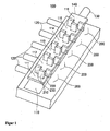
- the device 100 according to the FIG. 1 consists of a common channel-shaped venting chamber 110 with a common air outlet port 130 and five air inlet ports 120 for five actuators, not shown in this figure.
- the ventilation / deaeration chamber 110 has a chamber cover 140 which is shown floating in this figure above the ventilation / deaeration chamber 110.
- the chamber lid 140 has five approximately identical groups of protrusions 200 on the bottom 141 that divide the venting chamber 110 into six approximately equal sized partially sealed air chambers 111 to 116 for each of the five air inlet ports 120 and the common air outlet port 130.
- the formations 200 are designed in the form of a domino and have a rectangular cross section.
- the first formation 210 of each group 200 is located centrally and perpendicular to the main air-jet center 400.
- the two further formations 220, 230 are arranged laterally offset from one another symmetrically with respect to the main air flow medium axis 400.
- the three formations 210, 220, 230 form in their plan view an isosceles triangle 600, wherein the first formation 210 at the location of the tip of this triangle 600 and the other formations 220, 230 each represent a base corner point of this triangle 600, as the FIG. 3 illustrated.
- Projected in the main air flow direction 400, the three formations 210, 220, 230 of each group 200 form a gap-free wall 300 for each air chamber 111 to 116, as shown in FIGS FIG. 2 illustrated.
- the formations 210, 220, 230 are adapted to geometric dimensions of the ventilation / deaeration chamber 110 and adapted to the respective ventilation / venting chamber geometry.
- the two formations 220, 230 are arranged at the two edges of the inner side 141 of the chamber lid 140 so that they are 220, 230 at the contact outer surfaces flush with the side walls of the ventilation / deaeration chamber 110.
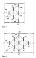
- FIG. 4 shows that the air flow 500 from an air inlet port 120 is braked by these three formations 210, 220, 230 and divided into three approximately equal-sized air streams 510, 520, 530.
- These three air streams 510, 520, 530 are reflected back from a respective one of the three formations 210, 220, 230 511, 521, 531.
- the air streams 511, 521, 531 reflected back from the formations 290, 220, 230 meet head-on with the subsequent air streams 510, 520, 530.
- the back-reflected air streams 511, 521, 531 and the subsequent air streams 510, 520, 530 meet head-on and form labyrinthine air swirls and interfere with each other.
- each forming group comprises six formations 210 to 260, these formations 210 to 260 being offset from each other in the main air flow direction so as to also form an isosceles triangle 600 in their plan view 210 to 260, wherein one of the formations 210 forms the top and two further formations 240 and 260 form the two base vertices of this triangle 600. Projected in the main air flow direction, the formations 210 to 260 likewise form a gap-free wall.
- FIG. 6 shows still another inventive arrangement of the formations. Accordingly, the formations 210, 211,..., 260 are arranged such that they form a rhombus 700 in their plan view. There are two formations 210, 211 on the first two vertices of the diamond 700, which through these two vertices the Air mainstream lift axle 400 runs. Two further formations 240, 260 lie on the two further corner points of diamond 700.
Landscapes
- Engineering & Computer Science (AREA)
- Physics & Mathematics (AREA)
- Fluid Mechanics (AREA)
- Mechanical Engineering (AREA)
- General Engineering & Computer Science (AREA)
- Chemical & Material Sciences (AREA)
- Analytical Chemistry (AREA)
- Fluid-Pressure Circuits (AREA)
Applications Claiming Priority (2)
| Application Number | Priority Date | Filing Date | Title |
|---|---|---|---|
| DE102007030636 | 2007-07-02 | ||
| DE102008015763.5A DE102008015763B4 (de) | 2007-07-02 | 2008-03-26 | Vorrichtung zur Be-/Entlüftung einer Mehrzahl von pneumatischen Aktuatoren, Sitz und Fahrzeug mit einer derartigen Vorrichtung |
Publications (2)
| Publication Number | Publication Date |
|---|---|
| EP2012022A2 true EP2012022A2 (fr) | 2009-01-07 |
| EP2012022A3 EP2012022A3 (fr) | 2012-08-29 |
Family
ID=39864900
Family Applications (1)
| Application Number | Title | Priority Date | Filing Date |
|---|---|---|---|
| EP08011773A Withdrawn EP2012022A3 (fr) | 2007-07-02 | 2008-06-30 | Dispositif d'aération d'une multitude d'actionneurs pneumatiques |
Country Status (1)
| Country | Link |
|---|---|
| EP (1) | EP2012022A3 (fr) |
Cited By (6)
| Publication number | Priority date | Publication date | Assignee | Title |
|---|---|---|---|---|
| CN105179779A (zh) * | 2014-05-01 | 2015-12-23 | 费希尔控制国际公司 | 用于数字的阀定位器的排放组件和方法 |
| WO2020186330A1 (fr) * | 2019-03-20 | 2020-09-24 | Leggett & Platt Canada Co. | Atténuateur de bruit pour module de commutation fluidique de système pneumatique |
| US11039975B2 (en) | 2018-08-29 | 2021-06-22 | Leggett & Platt Canada Co. | Pneumatic massage |
| US11432995B2 (en) | 2018-08-29 | 2022-09-06 | Leggett & Platt Canada Co. | Pneumatic massage |
| US11883358B2 (en) | 2018-03-05 | 2024-01-30 | Leggett & Platt Canada Co. | Pneumatic massage system |
| US12403807B2 (en) | 2020-02-24 | 2025-09-02 | Schukra Berndorf Gmbh | Pneumatic bladder arrangement for a seat and method for manufacturing the same |
Family Cites Families (5)
| Publication number | Priority date | Publication date | Assignee | Title |
|---|---|---|---|---|
| FR1145543A (fr) * | 1956-03-06 | 1957-10-28 | Renault | Perfectionnements aux silencieux |
| US4079809A (en) * | 1977-07-13 | 1978-03-21 | The United States Of America As Represented By The Secretary Of The Interior | Muffler for pneumatic drill |
| FR2398245A1 (fr) * | 1977-07-22 | 1979-02-16 | Outillage Air Comprime | Perfectionnement a un distributeur pneumatique sur embase |
| US4287962A (en) * | 1977-11-14 | 1981-09-08 | Industrial Acoustics Company | Packless silencer |
| DE3326802C2 (de) * | 1983-07-26 | 1986-03-20 | Festo KG, 7300 Esslingen | Anschlußblock |
-
2008
- 2008-06-30 EP EP08011773A patent/EP2012022A3/fr not_active Withdrawn
Cited By (9)
| Publication number | Priority date | Publication date | Assignee | Title |
|---|---|---|---|---|
| CN105179779A (zh) * | 2014-05-01 | 2015-12-23 | 费希尔控制国际公司 | 用于数字的阀定位器的排放组件和方法 |
| US11883358B2 (en) | 2018-03-05 | 2024-01-30 | Leggett & Platt Canada Co. | Pneumatic massage system |
| US11039975B2 (en) | 2018-08-29 | 2021-06-22 | Leggett & Platt Canada Co. | Pneumatic massage |
| US11432995B2 (en) | 2018-08-29 | 2022-09-06 | Leggett & Platt Canada Co. | Pneumatic massage |
| US11458066B2 (en) | 2018-08-29 | 2022-10-04 | Leggett & Platt Canada Co. | Pneumatic massage |
| US11752062B2 (en) | 2018-08-29 | 2023-09-12 | Leggett & Platt Canada Co. | Pneumatic massage |
| US12070436B2 (en) | 2018-08-29 | 2024-08-27 | Leggett & Platt Canada Co. | Pneumatic massage |
| WO2020186330A1 (fr) * | 2019-03-20 | 2020-09-24 | Leggett & Platt Canada Co. | Atténuateur de bruit pour module de commutation fluidique de système pneumatique |
| US12403807B2 (en) | 2020-02-24 | 2025-09-02 | Schukra Berndorf Gmbh | Pneumatic bladder arrangement for a seat and method for manufacturing the same |
Also Published As
| Publication number | Publication date |
|---|---|
| EP2012022A3 (fr) | 2012-08-29 |
Similar Documents
| Publication | Publication Date | Title |
|---|---|---|
| DE2604692A1 (de) | Schalldaempfer, insbesondere fuer gasturbinentriebwerke | |
| EP2012022A2 (fr) | Dispositif d'aération d'une multitude d'actionneurs pneumatiques | |
| EP0491175A2 (fr) | Filtre pour une installation de climatisation ou de chauffage d'un véhicule automobile | |
| EP3687872A1 (fr) | Amortisseur de bruit pour systèmes à air comprimé et procédé pour le produire | |
| DE112016005706T5 (de) | Verteileranordnung für Elektromagnetventile und diese verwendendes Elektromagnetventilcluster | |
| DE102007005371A1 (de) | Rohrdichtungselement und Verfahren zur seiner Herstellung | |
| DE69508640T2 (de) | Laminarströmungsschicht | |
| DE3121621C2 (de) | "Entlüftungseinrichtung für Kraftstofftanks von Fahrzeugen, insbesondere von Kraftfahrzeugen" | |
| WO2014012711A1 (fr) | Système de conduits d'air pour un véhicule ferroviaire destiné au transport de personnes | |
| DE19620921A1 (de) | Armaturenbrett für ein Kraftfahrzeug | |
| CH661101A5 (de) | Magnetventil. | |
| DE202004011630U1 (de) | Geräuschdämpfer für Drucklufteinrichtungen | |
| DE2830337A1 (de) | Ventil, welches in abhaengigkeit von der fluglage eines flugzeugs schwerkraftgesteuert ist | |
| WO2015052166A1 (fr) | Tubulure de remplissage pour un contenant de fluide de fonctionnement d'un véhicule à moteur | |
| DE202010005241U1 (de) | Lufttisch | |
| DE102008015763B4 (de) | Vorrichtung zur Be-/Entlüftung einer Mehrzahl von pneumatischen Aktuatoren, Sitz und Fahrzeug mit einer derartigen Vorrichtung | |
| EP2879722B1 (fr) | Isolateur à dégradation catalytique d'agents désinfectants | |
| DE3832256C2 (fr) | ||
| WO2003001120A1 (fr) | Dispositif d'humidification d'air | |
| DE102021206818A1 (de) | Abscheidevorrichtung | |
| EP2183482A1 (fr) | Machine à piston alternatif | |
| EP4212214A1 (fr) | Unité de filtration comprenant un bloc filtrant, une couche d'amortissement et un boîtier, et procédé de fabrication d'une telle unité de filtration | |
| DE19905036C2 (de) | Ventil | |
| DE102014102605A1 (de) | Absaugstutzen für eine Absaugvorrichtung | |
| DE10047068A1 (de) | Filter für eine Heizungs- oder Klimaanlage eines Kraftfahrzeuges |
Legal Events
| Date | Code | Title | Description |
|---|---|---|---|
| PUAI | Public reference made under article 153(3) epc to a published international application that has entered the european phase |
Free format text: ORIGINAL CODE: 0009012 |
|
| AK | Designated contracting states |
Kind code of ref document: A2 Designated state(s): AT BE BG CH CY CZ DE DK EE ES FI FR GB GR HR HU IE IS IT LI LT LU LV MC MT NL NO PL PT RO SE SI SK TR |
|
| AX | Request for extension of the european patent |
Extension state: AL BA MK RS |
|
| PUAL | Search report despatched |
Free format text: ORIGINAL CODE: 0009013 |
|
| AK | Designated contracting states |
Kind code of ref document: A3 Designated state(s): AT BE BG CH CY CZ DE DK EE ES FI FR GB GR HR HU IE IS IT LI LT LU LV MC MT NL NO PL PT RO SE SI SK TR |
|
| AX | Request for extension of the european patent |
Extension state: AL BA MK RS |
|
| RIC1 | Information provided on ipc code assigned before grant |
Ipc: F15B 15/22 20060101ALI20120725BHEP Ipc: F15B 15/20 20060101AFI20120725BHEP Ipc: F01N 1/08 20060101ALI20120725BHEP Ipc: F15B 21/04 20060101ALI20120725BHEP Ipc: F15D 1/00 20060101ALI20120725BHEP |
|
| AKX | Designation fees paid |
Designated state(s): DE FR IT SE |
|
| STAA | Information on the status of an ep patent application or granted ep patent |
Free format text: STATUS: THE APPLICATION IS DEEMED TO BE WITHDRAWN |
|
| 18D | Application deemed to be withdrawn |
Effective date: 20030301 |
|
| R18D | Application deemed to be withdrawn (corrected) |
Effective date: 20130301 |