EP2012072A2 - Wärmetauscher für ein Gasheizgrät und Gasheizgerät, insbesondere Brennwertkessel mit einem solchen Wärmetauscher - Google Patents
Wärmetauscher für ein Gasheizgrät und Gasheizgerät, insbesondere Brennwertkessel mit einem solchen Wärmetauscher Download PDFInfo
- Publication number
- EP2012072A2 EP2012072A2 EP20080159629 EP08159629A EP2012072A2 EP 2012072 A2 EP2012072 A2 EP 2012072A2 EP 20080159629 EP20080159629 EP 20080159629 EP 08159629 A EP08159629 A EP 08159629A EP 2012072 A2 EP2012072 A2 EP 2012072A2
- Authority
- EP
- European Patent Office
- Prior art keywords
- heat exchanger
- pipe
- grooves
- axis
- boiler
- Prior art date
- Legal status (The legal status is an assumption and is not a legal conclusion. Google has not performed a legal analysis and makes no representation as to the accuracy of the status listed.)
- Withdrawn
Links
Images


Classifications
-
- F—MECHANICAL ENGINEERING; LIGHTING; HEATING; WEAPONS; BLASTING
- F24—HEATING; RANGES; VENTILATING
- F24H—FLUID HEATERS, e.g. WATER OR AIR HEATERS, HAVING HEAT-GENERATING MEANS, e.g. HEAT PUMPS, IN GENERAL
- F24H1/00—Water heaters, e.g. boilers, continuous-flow heaters or water-storage heaters
- F24H1/22—Water heaters other than continuous-flow or water-storage heaters, e.g. water heaters for central heating
- F24H1/40—Water heaters other than continuous-flow or water-storage heaters, e.g. water heaters for central heating with water tube or tubes
- F24H1/43—Water heaters other than continuous-flow or water-storage heaters, e.g. water heaters for central heating with water tube or tubes helically or spirally coiled
Definitions
- the present invention relates to a heat exchanger, in particular for a gas boiler used to produce hot water, and to a gas boiler for producing hot water provided with said heat exchanger.
- the invention is particularly suitable for use in condensation boilers, to which reference is made in the following description purely by way of example.
- a gas boiler for producing hot water normally comprises a gas burner and at least one heat exchanger in which the combustion fumes produced by the burner transfer heat to circulating water.
- Condensation boilers condense the steam in the combustion fumes and also transfer the latent heat in the fumes to the water.
- the exchange of heat between the fumes and the water and the condensation of the fumes can be performed in separate heat exchangers or in a single heat exchanger which provides solely for heat exchange in a first portion and for both heat exchange and fume condensation in a second portion.
- the condensation boilers of the known type are provided with heat exchangers comprising a casing through which the fumes flow and housing a coiled pipe through which the water flows; the fumes flow between the turns of the pipe, over the outer surface of the pipe and transfer heat to the water flowing along the pipe.
- a known method for improving heat exchange efficiency consists of providing the outer surface of the coiled pipe with various types of fins.
- finned pipes are relatively complex and expensive to produce, and are not entirely satisfactory in terms of heat exchange efficiency.
- the purpose of the present invention is to provide a heat exchanger for a gas boiler for producing hot water that overcomes the drawbacks described above in a simple and inexpensive manner, both in terms of functionality and construction.
- one purpose of the invention is to provide a heat exchanger that is extremely efficient in terms of heat exchange and that is also simple and inexpensive to produce.
- a heat exchanger is produced as set forth in claim 1.
- reference number 1 indicates, as a whole, a gas boiler for producing hot water, in particular a condensation boiler; it is, however, understood that the invention may be applied to other kinds of boilers; the boiler 1 may be used to produce hot water for a sanitary water system and/or to supply a heating system.
- the general structure of the boiler 1 is essentially known and only the essential components thereof are described below; the boiler 1 comprises an outer structure 2, which is of a known type and only schematically illustrated in figure 1 , in which are housed a gas burner 3, a heat exchanger 4, a conduit 5 to supply an air/gas mixture to the burner 3, an exhaust pipe 6 for the combustion fumes produced in the burner 3, and a water circuit 7 for the water to be heated, which is only partially illustrated.
- the burner 3 is arranged inside the heat exchanger 4 and generates a flame 8 which burns the air/gas mixture supplied by the supply conduit 5; in the heat exchanger 4, the combustion fumes generated by the burner transfer heat to the water flowing in the circuit 7.
- the burner 3, of a type that is substantially known, is for example essentially cylindrical and has a cylindrical side wall provided with holes (not illustrated) for emitting the air/gas mixture and feeding the flame 8.
- the heat exchanger 4 is essentially cylindrical in shape and extends along an axis A; the heat exchanger 4 comprises a casing 11 through which the combustion fumes flow, a pipe 12 along which the water in the circuit 7 flows, and a baffle 13 or other equivalent diverting means for directing the combustion fumes along a fixed path, schematically illustrated by the arrow in figure 1 , inside the casing 11.
- the casing 11 comprises an essentially cylindrical side wall 14 arranged about the axis A and two walls 15, 16 of opposite ends, essentially parallel to one another and perpendicular to the axis A.
- the wall 15 supports the supply conduit 5 and the burner 3; the wall 16 supports the exhaust pipe 6.
- the burner 3 extends centrally inside the casing 11 essentially along the axis A and thus coaxially to the heat exchanger 4 and is provided with one end 17 fitted to the wall 15 and one free end 18, opposite the fitted end 17.
- the pipe 12 is arranged inside the casing 11 and is coiled about the axis A so as to form a succession of adjacent turns 20 arranged so as to be essentially parallel along the axis A in proximity to the side wall 14; the pipe 12 extends along a longitudinal axis C (curved) coiled about the axis A and is provided with a side wall 21, having an outer side surface 22 and an inner side surface 23, and two opposite ends provided with respective fittings 25 for connecting the pipe 12 to the water circuit 7.
- the coiled pipe 12 delimits inside the casing 11 a radially internal zone 26 and a radially external zone 27 arranged coaxially in relation to one another.
- the baffle 13 is arranged so as to be essentially perpendicular to the axis A in the casing 11 and specifically in the zone 26; the baffle 13 faces the free end 18 of the burner 3 and is arranged radially inside the pipe 12; the baffle 13 divides the zone 26 into two chambers 28, 29 aligned along the axis A; the chamber 28, adjacent to the wall 15, houses the burner 3 and also acts as a combustion chamber; the chamber 29, adjacent to the wall 16, is connected to the exhaust pipe 6.
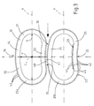
- the cross-section 32 of the pipe 12 (perpendicular to the longitudinal axis C of the pipe 12), which is preferably constant, comprises at least one outwardly concave portion 33 and one outwardly convex portion 34 opposite the concave portion 33.
- cross-section of the pipe 12 may differ from that illustrated, for example it could be essentially round, oval, elliptical, quadrangular or polygonal, with rounded edges and/or corners, etc., and may even not have any outwardly concave portions.
- each turn 20 comprises a concave surface portion 35 and a convex surface portion 36 of the surface 22 of the pipe 12, arranged on opposite sides of a central plane P of the turn 20 essentially perpendicular to the axis A.
- Adjacent turns 20a, 20b, face one another parallel to the axis A so that the concave portion 33 of one turn 20a faces the convex portion 34 of the adjacent turn 20b; thus, the concave surface portion 35 of a turn 20a also faces the convex surface portion 36 of the adjacent turn 20b.
- the turns 20 are arranged in succession along the axis A and are axially separated by respective gaps 40 defining essentially radial channels 41 through which the combustion fumes flow between the radially internal zone 26 and the radially external zone 27.
- the outer surface 22 of the pipe 12 is longitudinally grooved (on all or part of the surface), being provided with a plurality of longitudinal grooves 42 parallel to one another and to the longitudinal axis C of the pipe 12.
- At least the facing surface portions 35, 36, which delimit the channels 41, of adjacent turns 20 are provided with grooves 42.
- Adjacent turns 20 are thus provided with respective facing surface portions 35, 36 provided with respective pluralities of opposing longitudinal grooves 42; the grooves 42 of adjacent turns 20 provided on the facing surface portions 35, 36 protrude radially towards one another and may essentially be aligned with respect to one another, or staggered with respect to one another.
- the grooves 42 may be arranged solely on the facing surface portions 35, 36, and/or on other preferential surface portions of the surface 22, for example surface portions facing the burner 3 and thus facing the axis A, or essentially on the entire surface 22.
- each projecting part 43 is essentially perpendicular to the surface 22 and the projecting parts 43 are thus arranged radially or in a crown about the axis A on the surface 22.
- the known heat exchangers comprising a coiled pipe are provided with conventional fins the dimensions of which are generally comparable with the cross-dimensions of the pipe; however, according to the present invention, the surface 22 of the pipe 12 is only grooved, that is, it is provided with grooves 42 the depth of which is significantly less than the dimensions of the pipe 12; in other words, unlike with conventional fins, the height of the projecting parts 43 that delimit the grooves 42 is significantly less than the dimensions of the pipe 12.
- the depth of the grooves 42 is preferably not more than approximately 5 mm.
- Each groove 42 is delimited by a pair of lateral sides 45, essentially parallel to the longitudinal axis C of the pipe 12; in the example that is illustrated, the sides 45 converge towards a rounded base 46 of the groove 42; it is understood that the shape of the grooves 42 may differ from that described herein and illustrated merely by way of example.
- the sides 45 could be essentially parallel to one another, and could be essentially flat or even curved; the base 46 could be square-cornered, or even essentially flat.
- the cross-section of the grooves may be essentially triangular with a square-cornered or rounded vertex, essentially trapezoidal, rectangular or generally quadrangular or polygonal, with curved sides and/or square or rounded corners, etc., or a complex shape optimized to generate turbulence suitable to improve heat exchange efficiency.
- the grooves 42 may all be essentially identical to one another in terms of their shape and dimensions, or may have different shapes and/or dimensions according to the part of the surface 22 on which they are arranged.
- the inner surface 23 of the pipe 12 is also longitudinally grooved (on all or part of the surface), and is in turn provided with a plurality of longitudinal inner grooves 44 parallel to one another and to the longitudinal axis C of the pipe 12, identical in terms of geometry and dimensions to the grooves 42.
- the inner surface 23 may also be grooved (provided with grooves 44) on its entire inner perimeter or only on predefined preferential areas.
- the pipe 12 is preferably made of metal, for example aluminium; preferably, but not necessarily, the pipe 12 is manufactured by means of an extrusion process; in this case, the grooves 42 and/or the grooves 44 are most advantageously produced directly during the pipe 12 extrusion process.
- the boiler 1 provided with the heat exchanger 4 works in essentially the same way as similar boilers.
- the combustion fumes generated by the burner 3 in the chamber 28 flow from the chamber 28 to the radially external zone 27, between the turns 20 of the pipe 12 through the channels 41 in a radially external direction and transfer heat to the water flowing along the pipe 12; the combustion fumes thus flow past the baffle 13 over the side wall 14 of the casing 11, and then flow back between the turns 20 of the pipe 12 in a radially internal direction through the channels 41, complete the transfer of heat to the water in the pipe 12 and then flow into the exhaust pipe 6.
- the heat exchanger 4 achieves high heat exchange efficiency, due to the presence of the grooves 42 and/or of the grooves 44, which increase the heat exchange surface, generate surface turbulence which improves heat exchange and prolong the time for which the combustion fumes remain in contact with the side wall 21 of the pipe 12.
- the heat exchanger 4 is both simple and inexpensive to produce, particularly since the pipe 12 can be obtained directly by means of an extrusion process, during which the grooves 42, 44 can also be produced.
Landscapes
- Engineering & Computer Science (AREA)
- Physics & Mathematics (AREA)
- Thermal Sciences (AREA)
- Chemical & Material Sciences (AREA)
- Combustion & Propulsion (AREA)
- Mechanical Engineering (AREA)
- General Engineering & Computer Science (AREA)
- Heat-Exchange Devices With Radiators And Conduit Assemblies (AREA)
Applications Claiming Priority (1)
| Application Number | Priority Date | Filing Date | Title |
|---|---|---|---|
| ITMI20071331 ITMI20071331A1 (it) | 2007-07-04 | 2007-07-04 | Scambiatore di calore per una caldaia a gas e caldaia a gas, in particolare caldaia a condensazione, provvista di tale scambiatore di calore |
Publications (1)
| Publication Number | Publication Date |
|---|---|
| EP2012072A2 true EP2012072A2 (de) | 2009-01-07 |
Family
ID=39745672
Family Applications (1)
| Application Number | Title | Priority Date | Filing Date |
|---|---|---|---|
| EP20080159629 Withdrawn EP2012072A2 (de) | 2007-07-04 | 2008-07-03 | Wärmetauscher für ein Gasheizgrät und Gasheizgerät, insbesondere Brennwertkessel mit einem solchen Wärmetauscher |
Country Status (2)
| Country | Link |
|---|---|
| EP (1) | EP2012072A2 (de) |
| IT (1) | ITMI20071331A1 (de) |
Cited By (1)
| Publication number | Priority date | Publication date | Assignee | Title |
|---|---|---|---|---|
| WO2010140175A2 (en) | 2009-06-05 | 2010-12-09 | Riello S.P.A. | Elongated hollow member for a condensation heat exchanger of a gas condensation boiler for producing hot water |
-
2007
- 2007-07-04 IT ITMI20071331 patent/ITMI20071331A1/it unknown
-
2008
- 2008-07-03 EP EP20080159629 patent/EP2012072A2/de not_active Withdrawn
Cited By (2)
| Publication number | Priority date | Publication date | Assignee | Title |
|---|---|---|---|---|
| WO2010140175A2 (en) | 2009-06-05 | 2010-12-09 | Riello S.P.A. | Elongated hollow member for a condensation heat exchanger of a gas condensation boiler for producing hot water |
| WO2010140175A3 (en) * | 2009-06-05 | 2011-11-10 | Elbi International S.P.A. | Elongated hollow member for a condensation heat exchanger of a gas condensation boiler for producing hot water |
Also Published As
| Publication number | Publication date |
|---|---|
| ITMI20071331A1 (it) | 2009-01-05 |
Similar Documents
| Publication | Publication Date | Title |
|---|---|---|
| RU2472087C2 (ru) | Теплообменник, предназначенный, в особенности, для тепловых генераторов | |
| US8622030B2 (en) | Spiral heat exchanger for producing heating and/or sanitary use hot water, specifically designed for condensation applications | |
| US9976772B2 (en) | Sectional heat exchanger for use in a heat cell | |
| RU2018130211A (ru) | Конденсационный теплообменник, оснащенный теплообменным устройством | |
| EP3387356B1 (de) | Wärmetauscher mit doppelten konzentrischen rohrringen | |
| US10088196B2 (en) | Heat exchanger | |
| RU2012129345A (ru) | Нагревательный прибор для автомобиля | |
| US20170059201A1 (en) | Heat exchanger and manufacturing method for unit plate constituting heat exchanger | |
| ES2746928T3 (es) | Conjunto de tubos intercambiadores de calor | |
| RU2386905C1 (ru) | Теплогенератор | |
| EP2012072A2 (de) | Wärmetauscher für ein Gasheizgrät und Gasheizgerät, insbesondere Brennwertkessel mit einem solchen Wärmetauscher | |
| EP2012071A2 (de) | Wärmetauscher für ein Heizgerät and Gasheizgerät, insbesondere Brennwertheizgerät mit einem solchen Wärmetauscher | |
| RU2164642C1 (ru) | Водогрейный котел | |
| KR100798629B1 (ko) | 연소가스 다중통과구조를 갖는 보일러 열교환장치 | |
| RU2110730C1 (ru) | Цилиндрический котел | |
| RU184599U1 (ru) | Водотрубный котел | |
| RU34235U1 (ru) | Водогрейный водотрубный теплообменник | |
| RU53410U1 (ru) | Устройство для подогрева газа и нефти | |
| RU200074U1 (ru) | Теплообменник для водогрейного котла | |
| CN110118435B (zh) | 一种壁挂炉热交换器 | |
| KR200277473Y1 (ko) | 열교환기 | |
| CN109595813B (zh) | 一种全逆流防干烧燃气冷凝锅炉 | |
| EP3426986B1 (de) | Gliederwärmetauscher zur verwendung in einem gliederheizkessel | |
| CA2922855C (en) | Indirect fired heat exchanger | |
| RU86712U1 (ru) | Котел |
Legal Events
| Date | Code | Title | Description |
|---|---|---|---|
| PUAI | Public reference made under article 153(3) epc to a published international application that has entered the european phase |
Free format text: ORIGINAL CODE: 0009012 |
|
| AK | Designated contracting states |
Kind code of ref document: A2 Designated state(s): AT BE BG CH CY CZ DE DK EE ES FI FR GB GR HR HU IE IS IT LI LT LU LV MC MT NL NO PL PT RO SE SI SK TR |
|
| AX | Request for extension of the european patent |
Extension state: AL BA MK RS |
|
| RAP1 | Party data changed (applicant data changed or rights of an application transferred) |
Owner name: FONDITAL S.P.A. |
|
| STAA | Information on the status of an ep patent application or granted ep patent |
Free format text: STATUS: THE APPLICATION IS DEEMED TO BE WITHDRAWN |
|
| 18D | Application deemed to be withdrawn |
Effective date: 20140201 |