EP2012135B1 - Programme d'estimation d'état de charge, système de transport sans fil et procédé de charge - Google Patents
Programme d'estimation d'état de charge, système de transport sans fil et procédé de charge Download PDFInfo
- Publication number
- EP2012135B1 EP2012135B1 EP07850153.3A EP07850153A EP2012135B1 EP 2012135 B1 EP2012135 B1 EP 2012135B1 EP 07850153 A EP07850153 A EP 07850153A EP 2012135 B1 EP2012135 B1 EP 2012135B1
- Authority
- EP
- European Patent Office
- Prior art keywords
- battery
- soc
- charging
- vehicle
- voltage
- Prior art date
- Legal status (The legal status is an assumption and is not a legal conclusion. Google has not performed a legal analysis and makes no representation as to the accuracy of the status listed.)
- Ceased
Links
Images




Classifications
-
- G—PHYSICS
- G01—MEASURING; TESTING
- G01R—MEASURING ELECTRIC VARIABLES; MEASURING MAGNETIC VARIABLES
- G01R31/00—Arrangements for testing electric properties; Arrangements for locating electric faults; Arrangements for electrical testing characterised by what is being tested not provided for elsewhere
- G01R31/36—Arrangements for testing, measuring or monitoring the electrical condition of accumulators or electric batteries, e.g. capacity or state of charge [SoC]
-
- B—PERFORMING OPERATIONS; TRANSPORTING
- B60—VEHICLES IN GENERAL
- B60L—PROPULSION OF ELECTRICALLY-PROPELLED VEHICLES; SUPPLYING ELECTRIC POWER FOR AUXILIARY EQUIPMENT OF ELECTRICALLY-PROPELLED VEHICLES; ELECTRODYNAMIC BRAKE SYSTEMS FOR VEHICLES IN GENERAL; MAGNETIC SUSPENSION OR LEVITATION FOR VEHICLES; MONITORING OPERATING VARIABLES OF ELECTRICALLY-PROPELLED VEHICLES; ELECTRIC SAFETY DEVICES FOR ELECTRICALLY-PROPELLED VEHICLES
- B60L3/00—Electric devices on electrically-propelled vehicles for safety purposes; Monitoring operating variables, e.g. speed, deceleration or energy consumption
- B60L3/0023—Detecting, eliminating, remedying or compensating for drive train abnormalities, e.g. failures within the drive train
- B60L3/0046—Detecting, eliminating, remedying or compensating for drive train abnormalities, e.g. failures within the drive train relating to electric energy storage systems, e.g. batteries or capacitors
-
- B—PERFORMING OPERATIONS; TRANSPORTING
- B60—VEHICLES IN GENERAL
- B60L—PROPULSION OF ELECTRICALLY-PROPELLED VEHICLES; SUPPLYING ELECTRIC POWER FOR AUXILIARY EQUIPMENT OF ELECTRICALLY-PROPELLED VEHICLES; ELECTRODYNAMIC BRAKE SYSTEMS FOR VEHICLES IN GENERAL; MAGNETIC SUSPENSION OR LEVITATION FOR VEHICLES; MONITORING OPERATING VARIABLES OF ELECTRICALLY-PROPELLED VEHICLES; ELECTRIC SAFETY DEVICES FOR ELECTRICALLY-PROPELLED VEHICLES
- B60L53/00—Methods of charging batteries, specially adapted for electric vehicles; Charging stations or on-board charging equipment therefor; Exchange of energy storage elements in electric vehicles
- B60L53/10—Methods of charging batteries, specially adapted for electric vehicles; Charging stations or on-board charging equipment therefor; Exchange of energy storage elements in electric vehicles characterised by the energy transfer between the charging station and the vehicle
- B60L53/11—DC charging controlled by the charging station, e.g. mode 4
-
- B—PERFORMING OPERATIONS; TRANSPORTING
- B60—VEHICLES IN GENERAL
- B60L—PROPULSION OF ELECTRICALLY-PROPELLED VEHICLES; SUPPLYING ELECTRIC POWER FOR AUXILIARY EQUIPMENT OF ELECTRICALLY-PROPELLED VEHICLES; ELECTRODYNAMIC BRAKE SYSTEMS FOR VEHICLES IN GENERAL; MAGNETIC SUSPENSION OR LEVITATION FOR VEHICLES; MONITORING OPERATING VARIABLES OF ELECTRICALLY-PROPELLED VEHICLES; ELECTRIC SAFETY DEVICES FOR ELECTRICALLY-PROPELLED VEHICLES
- B60L58/00—Methods or circuit arrangements for monitoring or controlling batteries or fuel cells, specially adapted for electric vehicles
- B60L58/10—Methods or circuit arrangements for monitoring or controlling batteries or fuel cells, specially adapted for electric vehicles for monitoring or controlling batteries
- B60L58/12—Methods or circuit arrangements for monitoring or controlling batteries or fuel cells, specially adapted for electric vehicles for monitoring or controlling batteries responding to state of charge [SoC]
- B60L58/13—Maintaining the SoC within a determined range
-
- B—PERFORMING OPERATIONS; TRANSPORTING
- B60—VEHICLES IN GENERAL
- B60L—PROPULSION OF ELECTRICALLY-PROPELLED VEHICLES; SUPPLYING ELECTRIC POWER FOR AUXILIARY EQUIPMENT OF ELECTRICALLY-PROPELLED VEHICLES; ELECTRODYNAMIC BRAKE SYSTEMS FOR VEHICLES IN GENERAL; MAGNETIC SUSPENSION OR LEVITATION FOR VEHICLES; MONITORING OPERATING VARIABLES OF ELECTRICALLY-PROPELLED VEHICLES; ELECTRIC SAFETY DEVICES FOR ELECTRICALLY-PROPELLED VEHICLES
- B60L58/00—Methods or circuit arrangements for monitoring or controlling batteries or fuel cells, specially adapted for electric vehicles
- B60L58/10—Methods or circuit arrangements for monitoring or controlling batteries or fuel cells, specially adapted for electric vehicles for monitoring or controlling batteries
- B60L58/12—Methods or circuit arrangements for monitoring or controlling batteries or fuel cells, specially adapted for electric vehicles for monitoring or controlling batteries responding to state of charge [SoC]
- B60L58/14—Preventing excessive discharging
-
- B—PERFORMING OPERATIONS; TRANSPORTING
- B60—VEHICLES IN GENERAL
- B60L—PROPULSION OF ELECTRICALLY-PROPELLED VEHICLES; SUPPLYING ELECTRIC POWER FOR AUXILIARY EQUIPMENT OF ELECTRICALLY-PROPELLED VEHICLES; ELECTRODYNAMIC BRAKE SYSTEMS FOR VEHICLES IN GENERAL; MAGNETIC SUSPENSION OR LEVITATION FOR VEHICLES; MONITORING OPERATING VARIABLES OF ELECTRICALLY-PROPELLED VEHICLES; ELECTRIC SAFETY DEVICES FOR ELECTRICALLY-PROPELLED VEHICLES
- B60L58/00—Methods or circuit arrangements for monitoring or controlling batteries or fuel cells, specially adapted for electric vehicles
- B60L58/10—Methods or circuit arrangements for monitoring or controlling batteries or fuel cells, specially adapted for electric vehicles for monitoring or controlling batteries
- B60L58/12—Methods or circuit arrangements for monitoring or controlling batteries or fuel cells, specially adapted for electric vehicles for monitoring or controlling batteries responding to state of charge [SoC]
- B60L58/15—Preventing overcharging
-
- G—PHYSICS
- G01—MEASURING; TESTING
- G01R—MEASURING ELECTRIC VARIABLES; MEASURING MAGNETIC VARIABLES
- G01R31/00—Arrangements for testing electric properties; Arrangements for locating electric faults; Arrangements for electrical testing characterised by what is being tested not provided for elsewhere
- G01R31/36—Arrangements for testing, measuring or monitoring the electrical condition of accumulators or electric batteries, e.g. capacity or state of charge [SoC]
- G01R31/389—Measuring internal impedance, internal conductance or related variables
-
- H—ELECTRICITY
- H02—GENERATION; CONVERSION OR DISTRIBUTION OF ELECTRIC POWER
- H02J—ELECTRIC POWER NETWORKS; CIRCUIT ARRANGEMENTS OR SYSTEMS FOR SUPPLYING OR DISTRIBUTING ELECTRIC POWER; SYSTEMS FOR STORING ELECTRIC ENERGY
- H02J7/00—Circuit arrangements for charging or discharging batteries or for supplying loads from batteries
- H02J7/50—Circuit arrangements for charging or discharging batteries or for supplying loads from batteries acting upon multiple batteries simultaneously or sequentially
-
- H—ELECTRICITY
- H02—GENERATION; CONVERSION OR DISTRIBUTION OF ELECTRIC POWER
- H02J—ELECTRIC POWER NETWORKS; CIRCUIT ARRANGEMENTS OR SYSTEMS FOR SUPPLYING OR DISTRIBUTING ELECTRIC POWER; SYSTEMS FOR STORING ELECTRIC ENERGY
- H02J7/00—Circuit arrangements for charging or discharging batteries or for supplying loads from batteries
- H02J7/90—Regulation of charging or discharging current or voltage
- H02J7/933—Regulation of charging or discharging current or voltage the cycle being controlled or terminated in response to electric parameters
-
- B—PERFORMING OPERATIONS; TRANSPORTING
- B60—VEHICLES IN GENERAL
- B60L—PROPULSION OF ELECTRICALLY-PROPELLED VEHICLES; SUPPLYING ELECTRIC POWER FOR AUXILIARY EQUIPMENT OF ELECTRICALLY-PROPELLED VEHICLES; ELECTRODYNAMIC BRAKE SYSTEMS FOR VEHICLES IN GENERAL; MAGNETIC SUSPENSION OR LEVITATION FOR VEHICLES; MONITORING OPERATING VARIABLES OF ELECTRICALLY-PROPELLED VEHICLES; ELECTRIC SAFETY DEVICES FOR ELECTRICALLY-PROPELLED VEHICLES
- B60L2260/00—Operating Modes
- B60L2260/40—Control modes
- B60L2260/50—Control modes by future state prediction
- B60L2260/56—Temperature prediction, e.g. for pre-cooling
-
- G—PHYSICS
- G01—MEASURING; TESTING
- G01R—MEASURING ELECTRIC VARIABLES; MEASURING MAGNETIC VARIABLES
- G01R31/00—Arrangements for testing electric properties; Arrangements for locating electric faults; Arrangements for electrical testing characterised by what is being tested not provided for elsewhere
- G01R31/36—Arrangements for testing, measuring or monitoring the electrical condition of accumulators or electric batteries, e.g. capacity or state of charge [SoC]
- G01R31/3644—Constructional arrangements
- G01R31/3648—Constructional arrangements comprising digital calculation means, e.g. for performing an algorithm
-
- H—ELECTRICITY
- H02—GENERATION; CONVERSION OR DISTRIBUTION OF ELECTRIC POWER
- H02J—ELECTRIC POWER NETWORKS; CIRCUIT ARRANGEMENTS OR SYSTEMS FOR SUPPLYING OR DISTRIBUTING ELECTRIC POWER; SYSTEMS FOR STORING ELECTRIC ENERGY
- H02J2105/00—Networks for supplying or distributing electric power characterised by their spatial reach or by the load
- H02J2105/30—Networks for supplying or distributing electric power characterised by their spatial reach or by the load the load networks being external to vehicles, i.e. exchanging power with vehicles
- H02J2105/33—Networks for supplying or distributing electric power characterised by their spatial reach or by the load the load networks being external to vehicles, i.e. exchanging power with vehicles exchanging power with road vehicles
- H02J2105/37—Networks for supplying or distributing electric power characterised by their spatial reach or by the load the load networks being external to vehicles, i.e. exchanging power with vehicles exchanging power with road vehicles exchanging power with electric vehicles [EV] or with hybrid electric vehicles [HEV]
-
- Y—GENERAL TAGGING OF NEW TECHNOLOGICAL DEVELOPMENTS; GENERAL TAGGING OF CROSS-SECTIONAL TECHNOLOGIES SPANNING OVER SEVERAL SECTIONS OF THE IPC; TECHNICAL SUBJECTS COVERED BY FORMER USPC CROSS-REFERENCE ART COLLECTIONS [XRACs] AND DIGESTS
- Y02—TECHNOLOGIES OR APPLICATIONS FOR MITIGATION OR ADAPTATION AGAINST CLIMATE CHANGE
- Y02T—CLIMATE CHANGE MITIGATION TECHNOLOGIES RELATED TO TRANSPORTATION
- Y02T10/00—Road transport of goods or passengers
- Y02T10/60—Other road transportation technologies with climate change mitigation effect
- Y02T10/70—Energy storage systems for electromobility, e.g. batteries
-
- Y—GENERAL TAGGING OF NEW TECHNOLOGICAL DEVELOPMENTS; GENERAL TAGGING OF CROSS-SECTIONAL TECHNOLOGIES SPANNING OVER SEVERAL SECTIONS OF THE IPC; TECHNICAL SUBJECTS COVERED BY FORMER USPC CROSS-REFERENCE ART COLLECTIONS [XRACs] AND DIGESTS
- Y02—TECHNOLOGIES OR APPLICATIONS FOR MITIGATION OR ADAPTATION AGAINST CLIMATE CHANGE
- Y02T—CLIMATE CHANGE MITIGATION TECHNOLOGIES RELATED TO TRANSPORTATION
- Y02T10/00—Road transport of goods or passengers
- Y02T10/60—Other road transportation technologies with climate change mitigation effect
- Y02T10/7072—Electromobility specific charging systems or methods for batteries, ultracapacitors, supercapacitors or double-layer capacitors
-
- Y—GENERAL TAGGING OF NEW TECHNOLOGICAL DEVELOPMENTS; GENERAL TAGGING OF CROSS-SECTIONAL TECHNOLOGIES SPANNING OVER SEVERAL SECTIONS OF THE IPC; TECHNICAL SUBJECTS COVERED BY FORMER USPC CROSS-REFERENCE ART COLLECTIONS [XRACs] AND DIGESTS
- Y02—TECHNOLOGIES OR APPLICATIONS FOR MITIGATION OR ADAPTATION AGAINST CLIMATE CHANGE
- Y02T—CLIMATE CHANGE MITIGATION TECHNOLOGIES RELATED TO TRANSPORTATION
- Y02T90/00—Enabling technologies or technologies with a potential or indirect contribution to GHG emissions mitigation
- Y02T90/10—Technologies relating to charging of electric vehicles
- Y02T90/12—Electric charging stations
-
- Y—GENERAL TAGGING OF NEW TECHNOLOGICAL DEVELOPMENTS; GENERAL TAGGING OF CROSS-SECTIONAL TECHNOLOGIES SPANNING OVER SEVERAL SECTIONS OF THE IPC; TECHNICAL SUBJECTS COVERED BY FORMER USPC CROSS-REFERENCE ART COLLECTIONS [XRACs] AND DIGESTS
- Y02—TECHNOLOGIES OR APPLICATIONS FOR MITIGATION OR ADAPTATION AGAINST CLIMATE CHANGE
- Y02T—CLIMATE CHANGE MITIGATION TECHNOLOGIES RELATED TO TRANSPORTATION
- Y02T90/00—Enabling technologies or technologies with a potential or indirect contribution to GHG emissions mitigation
- Y02T90/10—Technologies relating to charging of electric vehicles
- Y02T90/14—Plug-in electric vehicles
Definitions
- the present invention relates to a battery SOC (State of Charge) estimation program, a wireless transit system in which battery mounted vehicles travel receiving electric power from the batteries , and a method of charging the batteries.
- SOC State of Charge
- ground charging equipment In a wireless transit system in which vehicles mounted with batteries travel by receiving electric power from the batteries, it is necessary that the batteries be charged by ground charging equipment.
- Ground charging equipment is provided at a plurality of premises such as stations because the battery is limited in its capacity to store electricity.
- stoppage time of the vehicles at stations is short, so fast charging of batteries is demanded.
- SOC State of Charge
- SOC State of Charge
- a temperature control means is provided, and battery temperature is maintained to a temperature desirable for SOC of the battery.
- charging power is controlled to be optimum by comparing DOD of the battery allowable for charging calculated from the temperature and voltage of the secondary battery with a DOD limit value allowable for charging determined dependent upon temperature, DOD, and voltage of the secondary battery memorized beforehand in a memory circuit, however, internal resistance of the battery changes depending on battery temperature variation and DOD (depth of discharge) allowable for charging varies according to the variation of internal resistance, so onerous control is needed taking temperature variation into consideration.
- the method disclosed in document 2 has an advantage that influence of battery temperature variation is eliminated by providing the temperature control means for the battery, however, the provision of the battery temperature control device causes a problem of complication in structure.
- JP2006054958A discloses a wireless transportation system for electrical vehicles incorporating SOC calculation.
- the present invention was made in light of the aforementioned background, and the object of the invention is to maintain SOC of batteries mounted on vehicles which travel on predetermined tracks by electric power supplied from the batteries in an appropriate range of battery SOC by estimating online with accuracy, thereby preventing occurrence of overcharging or over discharging of the batteries that will result in prevention of deterioration of the batteries, and at the same time to make quick charging of the batteries possible by enabling increase of charging current when charging the batteries.
- the present invention proposes a battery SOC estimation computer program comprising instructions which, when the program is executed by a computer, cause the computer to carry out a method of calculating state of charge (SOC) of a battery mounted on a vehicle in a wireless transit system, according to claim 1.
- SOC state of charge
- An equivalent circuit of the battery is set in the program, the equivalent circuit being composed of three circuit elements connected in series, a first component resistance which is influenced by instantaneous current variation, a circuit component consisting of a capacitance and a second component resistance connected in parallel which is influenced by slow and excessive response, and a terminal voltage of the battery.
- the equivalent circuit consists of three circuit elements connected in series, which are a first component resistance R 1 which is influenced by instantaneous current variation, a component circuit consisting of a capacitance C and a second component resistance R 2 connected in parallel which is influenced by slow and excessive response, and a terminal voltage E of the battery. Values of the elements vary depending on environment conditions such as temperature. Vc is polarization potential of C in the CR2 circuit, and E is electromotive force of the battery, i.e. open circuit voltage of the equivalent circuit. Relations between the current I and voltage V of the equivalent circuit are presented by equations (1) and (2) in FIG.1b .
- the first component resistance R 1 can be calculated for example from a voltage drop when discharging is started.
- open circuit voltage E of the equivalent circuit can be calculated from the equation (1) of FIG.1b .
- battery SOC can be calculated because there is a specific relation determined in accordance with battery characteristic between open circuit voltage E and battery SOC as well known in the field of the art.
- battery SOC can be maintained in an appropriate range and occurrence of overcharging of over discharging of the battery can be prevented, resulting in prevention of deterioration of the battery, and at the same time charging current when charging the battery can be increased.
- the result can be used effectively for evaluating SOH (State of Health) of the secondary battery.
- the invention proposes a wireless transit system for allowing a vehicle mounted with a battery unit and equipped with a computer which operates under a battery SOC estimation program to travel on predetermined tracks by electric power supplied from the battery unit, according to claim 2.
- Ground facilities each comprising a charging power source device and a ground power supply device connected to the charging power source device are established along the predetermined tracks, and the vehicle is provided with an in-vehicle power receiving device such that the power receiving device faces the ground power supply device when the vehicle makes a stop at a charging position in any of the ground facilities, means to detect current and voltage of the battery unit, a battery SOC calculating means comprising a computer which runs under the battery SOC estimation program according to claim 1, and a charge control device for controlling charging of the battery unit so that the charging of the battery unit is performed by the ground power supply device based on battery SOC calculated by the battery SOC calculating means.
- a wireless transit system has advantages that construction cost can be reduced and maintenance cost of overhead wire is made redundant because the overhead wire can be eliminated by mounting batteries for supplying power to drive the vehicle, and that kinetic energy of the vehicle can be recovered efficiently to the batteries for reutilization when decelerating the vehicle.
- charging of the batteries mounted on the vehicle is performed from ground charging facilities.
- the vehicle is allowed to make a stop at such a position that the in-vehicle power receiving device of the vehicle faces a ground power supply device of ground charging facilities provided at some positions along predetermined tracks in order to perform non-contact charging of the batteries mounted on the vehicle.
- the battery SOC calculating device having a computer which runs under the battery SOC estimation program, charging can be performed while estimating SOC of the battery online as described in the foregoing.
- the charge control means is provided in the vehicle to control charging based on battery SOC estimated by the battery SOP calculating device so that the battery is charged from the ground power supply device to an appropriate range of estimated SOC, occurrence of overcharging and over discharging can be prevented.
- the invention proposes a method of charging the battery unit mounted on the vehicle from the ground charging facility in the wireless transit system constituted as mentioned above, according to claim 3. Charging of the battery unit is performed so that charging current does not exceed an upper limit of charging current determined in consideration of the difference between a predetermined upper limit value and calculated value of open circuit voltage of the battery unit, and charging is stopped when SOC of the battery unit calculated by the battery SOC calculating means reaches a predetermined SOC.
- an upper limit of charging current is set in consideration of the difference between a predetermined upper limit value and calculated value of open circuit voltage of the battery, and charging is performed so that charging current does not exceed the upper limit, so occurrence of overcharging can be prevented.
- charging is stopped when SOC of the battery unit calculated by the battery SOC calculating means reaches a predetermined SOC, so the battery can be charged to a desired SOC in an appropriate range of SOC.
- SOC of the battery mounted on the vehicle can be calculated online, so battery SOC can be maintained in an appropriate range, therefore occurrence of overcharging and over discharging of the battery can be prevented, and deterioration of the battery can be prevented.
- the result can be used effectively for evaluating SOH (State of Health) of the secondary battery.
- the vehicle is equipped with the battery SOC calculating device having a computer which runs under the battery SOC estimation program, charging can be performed while estimating SOC of the battery online.
- the charge control means is provided in the vehicle to control charging based on battery SOC estimated by the battery SOP calculating device so that the battery is charged from the ground power supply device to an appropriate range of estimated SOC, occurrence of overcharging and over discharging can be prevented, and as a result deterioration of the battery can be prevented.
- upper limit of charging current is determined in consideration of the difference between a predetermined upper limit value and calculated value of open circuit voltage of the battery, and the battery is charged so that charging current does not exceed the upper limit, so overcharging is prevented, as a result, deterioration is prevented.
- Charging is stopped when SOC of the battery unit calculated by the battery SOC calculating means reaches a predetermined SOC, so the battery can be charged to a desired SOC in an appropriate range of SOC.
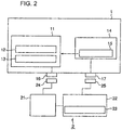
- FIG.2 is an embodiment of a wireless transit system according to the present invention.
- a vehicle 1 is a vehicle that travels on predetermined tracks, for example a vehicle travels in a LRT transit system.
- a controller 11 for controlling the vehicle totally including traveling and others is mounted on the vehicle 1.
- a secondary battery 14 such as a lithium ion secondary battery is mounted on the vehicle 1, current and voltage of the secondary battery 14 are detected by a current and voltage detecting means 15, and the detected values are sent to the controller 11.
- a charged state battery SOC calculating means 12 having a computer which operates under the program for estimating SOC of the secondary battery 14, and a charge control means 13 for controlling SOC of the secondary battery 14 based on the SOC of the secondary battery 14 estimated by the calculating means 12.
- Charge control will be performed by the control means while communication being established between an in-vehicle communication device 16 mounted on the vehicle 1 and a ground communication device 24 of a ground charging control equipment 21 provided on the ground.
- an in-vehicle power receiving device 17 is installed on the vehicle 1 for receiving electric power from a ground power supply device 25.
- Non-contact power supply is performed from the ground power supply device 25 to the in-vehicle power receiving device 17 when the vehicle 1 makes a stop so that the in-vehicle power receiving device 17 faces the ground power supply device 25 to charge the secondary battery 14.
- Ground charging facilities 2 are provided in premises such as stations, a charging power source device 22 and the ground charging control equipment 21 are installed in the ground facility, and electric power is supplied to the vehicle from the charging power source device 22 via the ground power supply device 25.
- the charging power source device 22 is provided with a charging current (power) setting means 23. Electric power to be supplied from the charging power source device 22 is determined beforehand by the charging current (power) setting means 23.
- the charging power source device 22 stops current supply upon receiving a charge stop signal form the ground charging control equipment 21.
- target SOC of the battery to stop charging is set to be in a rage of about 60 to 85% in order to prevent occurrence of over charge or over discharge while the vehicle is traveling, even if variation of characteristic of the battery depending on temperature is taken into consideration.
- Target SOC to stop charging and charging current determined beforehand may be varied depending on stations at which batteries are charged. The larger the charging current is, the more quickly the battery is charged.
- FIG.3 is a flowchart of a battery SOC estimating program to run a computer installed in the battery SOC calculating means 12. In the program is prepared the equivalent circuit shown in FIG.1 as the equivalent circuit of the secondary battery 14.
- Values of elements in the equivalent circuit are calculated online according to the flowchart of FIG.3 .
- firstly variations in current and voltage of the secondary battery 14 are detected online by the current and voltage detecting means 15 (steps 1 and 2), first component resistance R 1 is calculated from the variations (step 4).
- first component resistance R 1 is calculated from the variations (step 4).
- detected variation of current is smaller than a smallest preset value, it is regarded as noise and calculation of values of the first component resistance R 1 , second component resistance R 2 , and capacitance C is not performed, instead value of Vc calculated in the previous flow is used (step 3).
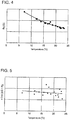
- FIG.4 is a graph showing a relation between the first component resistance R 1 versus temperature
- actual measurement values are plotted.
- the first component resistance R 1 varies depending on temperature, but ⁇ and k do not depend on temperature and a constant value respectively which is specific to the second battery 14, although the measurement values scatter somewhat.
- voltage Vc of the equivalent component circuit consisting of the capacitance C and second component resistance R 2 can be calculated by substituting the values of the second component resistance R 2 and capacitance C calculated in steps 5 and 6 into an equation of step 7. Then by substituting the calculated value of Vc into an equation of step 8, open circuit voltage E which corresponds to electromotive force of the battery can be calculated.
- open circuit voltage E As a relation between the open circuit voltage E and battery SOC is determined by a function defined by the specific characteristic of the secondary battery 14, SOC of charged battery can be calculated using the open circuit voltage E as shown in step 9.
- An example of relation of open circuit voltage E versus SOC of a charged battery is showing schematically in FIG.7 .
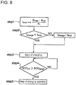
- SOC of the second battery in a charged state can be calculated following the steps of a procedure mentioned above. After SOC in a charged state is calculated, charging operation is performed following steps of a procedure shown in FIG.8 .
- an upper limit value I limit of charging current is determined by multiplying (E max -E( n ))/R 1 by ⁇ , where E max is an upper limit of electromotive force(open circuit voltage) of the battery 14, E (n) is electromotive force of the battery calculated in step 8 of the flowchart of FIG.3 , and ⁇ is a safety factor.
- Charging current I charge is controlled so that it does not exceed a maximum limit in step 2, and charging is started (step 3).
- SOC of the charged battery reached SOC target
- a target SOC of the battery to stop charging step 4
- charging operation is stopped (step 5).
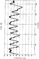
- FIG.9 An example of measurement of monitor voltage (V in FIG.1 ) and open circuit voltage (E in FIG.1 ) is shown in FIG.9 . It is recognized from FIG.9 that open circuit voltage E is detected with voltage variation due to current supply being filtered. In FIG.10 is shown an example of variation of battery SOC estimated according to the invention as the time elapses.
- SOC in charged state of the second battery 14 mounted on the vehicle 1 can be estimated with accuracy, so SOC of battery can be maintained in an appropriate range. Therefore, occurrence of overcharge of over discharge of the secondary battery 14 can be prevented, and as a result deterioration of the second battery can be prevented.
- the upper limit value I limit of charging current is determined corresponding to the value of (E max -E (n) )/R 1 of the equivalent circuit of the battery 14 and charging is performed so that charging current does not exceed the upper limit value, so occurrence of overcharging of the battery can be prevented, deterioration of the battery can be prevented, charging current can be increased, and quick charge can be possible when the vehicle makes a stop at stations. Further, as charging is stopped when SOC of the battery calculated by the charged state battery SOC calculating means 12 reaches the predetermined target state-of-charge SOC target , the battery can be charged to a desired state-of-charge in an appropriate range of SOC.
- occurrence of overcharging and over discharging are prevented by charging the batteries to an appropriate state of charge of the batteries thereby preventing deterioration of the batteries, and charging current can be increased making it possible to perform quick charge when the vehicles make a stop at stations.
Landscapes
- Engineering & Computer Science (AREA)
- Power Engineering (AREA)
- Transportation (AREA)
- Mechanical Engineering (AREA)
- Life Sciences & Earth Sciences (AREA)
- Sustainable Development (AREA)
- Sustainable Energy (AREA)
- Physics & Mathematics (AREA)
- General Physics & Mathematics (AREA)
- Charge And Discharge Circuits For Batteries Or The Like (AREA)
- Secondary Cells (AREA)
- Electric Propulsion And Braking For Vehicles (AREA)
Claims (3)
- Programme d'estimation de SOC de batterie comprenant des instructions qui, lorsque le programme est exécuté par un ordinateur, amènent l'ordinateur à réaliser un procédé de calcul d'état de charge (SOC) d'une batterie (14) montée sur un véhicule (1) dans un système de transit sans fil, le procédé comprenant les étapes suivantes :définir un circuit équivalent de la batterie (14), le circuit équivalent étant composé de trois éléments de circuit connectés en série, d'une première résistance de composant (R1) qui est influencée par une variation de courant instantanée, d'un circuit composant consistant en une capacité (C) et une deuxième résistance de composant (R2) connectées en parallèle qui est influencé par une réponse lente et excessive, et d'une tension à vide (E) du circuit équivalent de la batterie (14),recevoir des valeurs de mesure de courant et de tension de la batterie (14), calculer, sur la base des valeurs de mesure, des valeurs prédéterminées du rapport (k) entre la deuxième résistance de composant (R2) et la première résistance de composant (R1) et de la constante de temps (τ) en tant que produit de la capacité (C) et de la deuxième résistance de composant (R2), en tant que valeurs constantes spécifiques de la batterie (14), etcalculer (a) une valeur de la première résistance de composant (R1) à partir des variations détectées des valeurs de mesure de courant et de tension de la batterie (14), (b) une valeur de la deuxième résistance de composant (R2) à partir de la valeur calculée de la première résistance de composant (R1) et d'une valeur prédéterminée dudit rapport (k), (c) une valeur de la capacité (C) à partir de la valeur calculée de la deuxième résistance de composant (R2) et d'une valeur prédéterminée de ladite constante de temps (τ), (d) un potentiel (Vc) du circuit composant à partir des valeurs calculées de la deuxième résistance de composant (R2) et de la capacité (C), (e) une valeur de la tension à vide (E) à partir du potentiel calculé du circuit composant, et (f) le SOC à partir de la valeur calculée de la tension à vide (E).
- Système de transit sans fil destiné à permettre à un véhicule (1) muni d'une unité de batterie (14) et équipé d'un moyen de calcul de SOC de batterie (12) ayant un ordinateur qui est configuré pour fonctionner dans le cadre d'un programme d'estimation de SOC de batterie afin de se déplacer sur des voies prédéterminées par de l'électricité fournie depuis l'unité de batterie (14), le système de transit sans fil comprenant :des installations au sol (2) comprenant chacune un dispositif de source électrique de charge (22) et un dispositif d'alimentation électrique au sol (25) connecté au dispositif de source électrique de charge (22), les installations au sol (2) étant établies le long des voies prédéterminées ;un dispositif de réception électrique embarqué (17) prévu dans le véhicule (1) et configuré pour recevoir de l'électricité depuis le dispositif d'alimentation électrique au sol (25) à une position où le dispositif de réception électrique (17) est face au dispositif d'alimentation électrique au sol (25) lorsque le véhicule (1) effectue un arrêt à la position de charge dans l'une quelconque des installations au sol (2) ;des moyens (15) prévus dans le véhicule (1) et configurés pour détecter un courant et une tension de l'unité de batterie (14) ;le moyen de calcul de SOC de batterie (12) prévu dans le véhicule (1) et configuré pour calculer le SOC en exécutant le programme d'estimation de SOC de batterie selon la revendication 1 ; etun dispositif de commande de charge (13) prévu dans le véhicule (1) et configuré pour commander la charge de l'unité de batterie (14) de sorte que la charge de l'unité de batterie (14) soit réalisée par le dispositif d'alimentation électrique au sol (25) sur la base du SOC calculé par le moyen de calcul de SOC de batterie (12).
- Procédé de charge de l'unité de batterie (14) montée sur le véhicule (1) à partir de l'installation de charge au sol (2) dans le système de transit sans fil selon la revendication 2, le procédé comprenant les étapes suivantes :la détermination d'une limite supérieure de courant de charge (llimit) déterminée compte tenu de la différence entre une valeur limite supérieure prédéterminée (Emax) et une valeur calculée de la tension à vide (E) de l'unité de batterie (14),l'utilisation du dispositif de commande de charge (13) pour commander le courant de charge (lcharge) de sorte qu'il ne dépasse pas la limite supérieure (llimit),l'utilisation du moyen de calcul de SOC de batterie (12) pour calculer le SOC de la batterie (14) par le procédé de la revendication 1, etl'arrêt de la charge de l'unité de batterie (14) lorsque le SOC de l'unité de batterie (14) calculé par le moyen de calcul de SOC de batterie (12) atteint un SOC prédéterminé (SOCcible).
Applications Claiming Priority (2)
| Application Number | Priority Date | Filing Date | Title |
|---|---|---|---|
| JP2006324643A JP4884945B2 (ja) | 2006-11-30 | 2006-11-30 | 充電状態予測プログラム、架線レス交通システム及びその充電方法 |
| PCT/JP2007/073536 WO2008066203A1 (fr) | 2006-11-30 | 2007-11-29 | Programme d'estimation d'état de charge, système de transport sans fil et procédé de charge |
Publications (3)
| Publication Number | Publication Date |
|---|---|
| EP2012135A1 EP2012135A1 (fr) | 2009-01-07 |
| EP2012135A4 EP2012135A4 (fr) | 2017-01-25 |
| EP2012135B1 true EP2012135B1 (fr) | 2021-01-06 |
Family
ID=39467983
Family Applications (1)
| Application Number | Title | Priority Date | Filing Date |
|---|---|---|---|
| EP07850153.3A Ceased EP2012135B1 (fr) | 2006-11-30 | 2007-11-29 | Programme d'estimation d'état de charge, système de transport sans fil et procédé de charge |
Country Status (7)
| Country | Link |
|---|---|
| US (1) | US7888912B2 (fr) |
| EP (1) | EP2012135B1 (fr) |
| JP (1) | JP4884945B2 (fr) |
| KR (1) | KR101073148B1 (fr) |
| CN (1) | CN101454682B (fr) |
| CA (1) | CA2651334C (fr) |
| WO (1) | WO2008066203A1 (fr) |
Families Citing this family (37)
| Publication number | Priority date | Publication date | Assignee | Title |
|---|---|---|---|---|
| US8111037B2 (en) * | 2008-06-27 | 2012-02-07 | GM Global Technology Operations LLC | Method for battery state-of-health monitoring using battery voltage during vehicle starting |
| GB2463297A (en) * | 2008-09-09 | 2010-03-10 | Ricardo Uk Ltd | Determining a power source state of charge using an equivalent circuit model |
| JP5091067B2 (ja) * | 2008-09-17 | 2012-12-05 | カルソニックカンセイ株式会社 | 組電池の残量推定方法及び装置 |
| US8008893B2 (en) * | 2009-02-06 | 2011-08-30 | Cobasys, Llc | Battery analysis system |
| JP4576465B2 (ja) * | 2009-03-06 | 2010-11-10 | 三菱重工業株式会社 | 架線レス交通車両の充電方法及び充電システム |
| KR101277733B1 (ko) * | 2010-01-27 | 2013-06-24 | 주식회사 엘지화학 | 배터리의 soc를 추정하는 장치 및 방법 |
| US8232765B2 (en) | 2010-03-13 | 2012-07-31 | James A Billmaier | Automatic and dynamic home electricity load balancing for the purpose of EV charging |
| US9091735B2 (en) * | 2010-10-26 | 2015-07-28 | GM Global Technology Operations LLC | Method for determining a state of a rechargeable battery device in real time |
| US9354277B2 (en) * | 2010-10-29 | 2016-05-31 | Gm Global Technology Operatins Llc | Apparatus of SOC estimation during plug-in charge mode |
| US9564762B2 (en) | 2010-11-02 | 2017-02-07 | Navitas Solutions | Fault tolerant wireless battery area network for a smart battery management system |
| CN103270666B (zh) | 2010-11-02 | 2018-01-30 | 纳维达斯解决方案有限公司 | 用于智能电池管理的无线电池区域网络 |
| US9559530B2 (en) | 2010-11-02 | 2017-01-31 | Navitas Solutions | Fault tolerant wireless battery area network for a smart battery management system |
| JP2012105467A (ja) * | 2010-11-11 | 2012-05-31 | Diamond Electric Mfg Co Ltd | 充電装置 |
| US9201121B2 (en) * | 2010-12-06 | 2015-12-01 | Texas Instruments Incorporated | System and method for sensing battery capacity |
| US8983657B2 (en) * | 2011-08-31 | 2015-03-17 | Caterpillar Inc. | System and method of managing vehicles deployed in a worksite |
| EP2838151B1 (fr) * | 2012-04-13 | 2017-08-23 | LG Chem, Ltd. | Système de pile rechargeable comprenant un matériau cathode mélangé, et appareil et méthode de gestion de pile rechargeable |
| JP5677362B2 (ja) * | 2012-04-27 | 2015-02-25 | 本田技研工業株式会社 | 電源劣化判定装置 |
| JP5772737B2 (ja) * | 2012-06-21 | 2015-09-02 | トヨタ自動車株式会社 | 全電池容量推定方法 |
| US9085238B2 (en) | 2013-01-11 | 2015-07-21 | Johnson Controls Technology Company | Energy storage control system and method |
| WO2014179313A1 (fr) * | 2013-04-29 | 2014-11-06 | Enerdel, Inc. | Système et procédé de surveillance d'état de santé d'un système de batterie |
| JP6201968B2 (ja) * | 2014-11-27 | 2017-09-27 | トヨタ自動車株式会社 | 充電制御装置 |
| CN104852436B (zh) * | 2015-05-25 | 2016-12-07 | 泉州市南安市轴飞电子科技有限公司 | 一种应用于新能源车的充电桩 |
| DE102016000668A1 (de) * | 2016-01-22 | 2017-07-27 | Audi Ag | Verfahren zur Ermittlung einer Leistungsfähigkeitsinformation einer Batterie eines kraftfahrzeugseitigen, an einen Gleichspannungswandler angebundenen Bordnetzes und Kraftfahrzeug |
| DE112016006782T5 (de) * | 2016-05-25 | 2019-01-24 | Ford Global Technologies, Llc | Verfahren und Vorrichtungen zum Aufladen von Elektrofahrzeugen |
| CN105929338B (zh) * | 2016-05-30 | 2018-12-25 | 北京大学深圳研究生院 | 一种测量电池状态的方法及其应用 |
| CN105896680B (zh) * | 2016-06-12 | 2019-02-15 | 江西飞尚科技有限公司 | 一种电容器充电和放电电压单独可控制的方法 |
| US11318844B2 (en) * | 2017-11-26 | 2022-05-03 | Delta Electronics, Inc. | On-board charging device and operating method thereof |
| KR102783337B1 (ko) * | 2018-02-20 | 2025-03-19 | 주식회사 엘지에너지솔루션 | 에너지 저장 시스템의 충전용량 산출 장치 및 방법 |
| JP6744886B2 (ja) * | 2018-03-20 | 2020-08-19 | 株式会社東芝 | 電池安全性評価装置、電池安全性評価方法、プログラム、制御回路及び蓄電システム |
| CN112428878A (zh) * | 2019-08-26 | 2021-03-02 | 上海汽车集团股份有限公司 | 一种软件刷新控制方法、装置及车联网设备 |
| US12042043B2 (en) | 2020-06-11 | 2024-07-23 | Kohler Co. | Temperature tracking mirror |
| US12588901B2 (en) | 2020-06-11 | 2026-03-31 | Kohler Co. | Health care mirror |
| US20220385076A1 (en) * | 2021-05-28 | 2022-12-01 | Deere & Company | Control system for managing battery cells with one or more dc-to-dc converters |
| CN113253137B (zh) * | 2021-06-07 | 2021-09-24 | 蜂巢能源科技有限公司 | 确定电池包荷电状态的装置和方法 |
| CN114030357A (zh) * | 2021-07-14 | 2022-02-11 | 山西赛坦科技有限公司 | 一种防止bms回充过流的控制装置及控制方法 |
| JP7552521B2 (ja) * | 2021-07-20 | 2024-09-18 | トヨタ自動車株式会社 | 充電量算出装置および充電システム |
| KR102927506B1 (ko) | 2023-05-18 | 2026-02-19 | 주식회사 남전사 | 고주파 대역 무선 계측 및 계량 방법 |
Family Cites Families (26)
| Publication number | Priority date | Publication date | Assignee | Title |
|---|---|---|---|---|
| DE4014696C3 (de) * | 1990-05-08 | 2003-07-17 | Bosch Gmbh Robert | Anordnung und Verfahren zum Laden eines Akkumulators einer Transportvorrichtung mit eigenem Elektro-Antrieb |
| JP3006293B2 (ja) * | 1992-07-16 | 2000-02-07 | トヨタ自動車株式会社 | 電池残存容量計 |
| DE4236286A1 (de) * | 1992-10-28 | 1994-05-05 | Daimler Benz Ag | Verfahren und Anordnung zum automatischen berührungslosen Laden |
| JPH06343203A (ja) * | 1993-06-01 | 1994-12-13 | Nissan Motor Co Ltd | 電気自動車の充電装置 |
| JP3274287B2 (ja) * | 1994-08-25 | 2002-04-15 | 矢崎総業株式会社 | 電池残存容量測定装置 |
| JP3121732B2 (ja) * | 1994-11-04 | 2001-01-09 | 三菱電機株式会社 | 二次電池のパラメータ測定方法ならびにそれを用いた二次電池の充放電制御方法および寿命予測方法、ならびに、二次電池の充放電制御装置およびそれを用いた電力貯蔵装置 |
| JPH08240647A (ja) * | 1995-03-03 | 1996-09-17 | Yazaki Corp | 電池残存容量算出方法及び電池残存容量測定装置 |
| JPH10108380A (ja) | 1996-09-26 | 1998-04-24 | Sony Corp | 電気自動車用二次電池の充電装置およびその充電方法 |
| JP2001021628A (ja) * | 1999-07-02 | 2001-01-26 | Yazaki Corp | 温度センサを用いた充電可能容量算出機能付きバッテリ容量測定装置 |
| JP4477185B2 (ja) * | 2000-02-22 | 2010-06-09 | 古河電気工業株式会社 | 鉛蓄電池の特性評価方法および鉛蓄電池の特性評価装置 |
| JP2002189066A (ja) * | 2000-12-22 | 2002-07-05 | Hitachi Ltd | 二次電池残量推定法 |
| JP2003090869A (ja) * | 2001-07-09 | 2003-03-28 | Yokogawa Electric Corp | インピーダンスの測定装置 |
| US6639385B2 (en) * | 2001-08-07 | 2003-10-28 | General Motors Corporation | State of charge method and apparatus |
| JP3714246B2 (ja) * | 2001-12-18 | 2005-11-09 | 日産自動車株式会社 | 二次電池の充電率推定装置 |
| JP4157317B2 (ja) * | 2002-04-10 | 2008-10-01 | 株式会社日立製作所 | 状態検知装置及びこれを用いた各種装置 |
| JP3771526B2 (ja) * | 2002-10-21 | 2006-04-26 | 株式会社日立製作所 | 二次電池評価方法および蓄電装置 |
| US7324902B2 (en) * | 2003-02-18 | 2008-01-29 | General Motors Corporation | Method and apparatus for generalized recursive least-squares process for battery state of charge and state of health |
| JP2004301782A (ja) * | 2003-03-31 | 2004-10-28 | Yazaki Corp | 満充電状態検出装置及びその方法、充電状態検出装置及びその方法、劣化度検出装置及びその方法 |
| JP4074596B2 (ja) * | 2004-03-18 | 2008-04-09 | 日立マクセル株式会社 | 充電電池あるいは充電電池パック |
| US7554295B2 (en) * | 2004-04-06 | 2009-06-30 | Cobasys, Llc | Determination of IR-free voltage in hybrid vehicle applications |
| JP2006003637A (ja) | 2004-06-17 | 2006-01-05 | Canon Inc | 投写光学系、及びそれを用いた投写型表示装置 |
| JP4220946B2 (ja) | 2004-08-11 | 2009-02-04 | 三菱重工業株式会社 | 電気車両、架線レス交通システム及び架線レス交通システムの制御方法 |
| US20060103348A1 (en) * | 2004-11-15 | 2006-05-18 | Melichar Robert J | Maximum and minimum power limit calculator for parallel battery subpacks |
| JP4767558B2 (ja) * | 2005-03-07 | 2011-09-07 | 日立ビークルエナジー株式会社 | 電源装置用状態検知装置,電源装置及び電源装置に用いられる初期特性抽出装置 |
| JP4571000B2 (ja) * | 2005-03-29 | 2010-10-27 | 富士重工業株式会社 | 蓄電デバイスの残存容量演算装置 |
| JP4709654B2 (ja) * | 2006-01-11 | 2011-06-22 | 三菱重工業株式会社 | 交通システム |
-
2006
- 2006-11-30 JP JP2006324643A patent/JP4884945B2/ja not_active Expired - Fee Related
-
2007
- 2007-11-29 WO PCT/JP2007/073536 patent/WO2008066203A1/fr not_active Ceased
- 2007-11-29 CN CN200780019887.7A patent/CN101454682B/zh not_active Expired - Fee Related
- 2007-11-29 CA CA2651334A patent/CA2651334C/fr not_active Expired - Fee Related
- 2007-11-29 KR KR1020087029293A patent/KR101073148B1/ko not_active Expired - Fee Related
- 2007-11-29 US US12/302,851 patent/US7888912B2/en active Active
- 2007-11-29 EP EP07850153.3A patent/EP2012135B1/fr not_active Ceased
Non-Patent Citations (1)
| Title |
|---|
| None * |
Also Published As
| Publication number | Publication date |
|---|---|
| CA2651334C (fr) | 2013-04-09 |
| US20090195219A1 (en) | 2009-08-06 |
| WO2008066203A1 (fr) | 2008-06-05 |
| JP2008141846A (ja) | 2008-06-19 |
| CN101454682A (zh) | 2009-06-10 |
| EP2012135A4 (fr) | 2017-01-25 |
| HK1128963A1 (en) | 2009-11-13 |
| CN101454682B (zh) | 2015-10-21 |
| KR20090016678A (ko) | 2009-02-17 |
| KR101073148B1 (ko) | 2011-10-12 |
| JP4884945B2 (ja) | 2012-02-29 |
| US7888912B2 (en) | 2011-02-15 |
| CA2651334A1 (fr) | 2008-06-05 |
| EP2012135A1 (fr) | 2009-01-07 |
Similar Documents
| Publication | Publication Date | Title |
|---|---|---|
| EP2012135B1 (fr) | Programme d'estimation d'état de charge, système de transport sans fil et procédé de charge | |
| CN114050633B (zh) | 一种锂电池储能系统的动态管控方法、装置和电子设备 | |
| KR102791127B1 (ko) | 배터리 관리 시스템, 배터리 팩, 전기 차량 및 배터리 관리 방법 | |
| EP3352289B1 (fr) | Dispositif de commande de batterie rechargeable | |
| US12539781B2 (en) | Management device and power supply system | |
| US9634498B2 (en) | Electrical storage system and equalizing method | |
| US20160096433A1 (en) | Bus leakage resistance estimation for electrical isolation testing and diagnostics | |
| US9658293B2 (en) | Power supply unit, vehicle and storage battery unit equipped with power supply unit, and remaining capacity detecting method of battery | |
| US9260033B2 (en) | Power supply device and vehicle including the same | |
| US20140015537A1 (en) | Control system for battery assembly and method of determining reuse of battery assembly | |
| US11269392B2 (en) | System and method for maintaining power source | |
| US20150303532A1 (en) | Battery System and Associated Method for Determining the Internal Resistance of Battery Cells or Battery Modules of Said Battery System | |
| CN105572540B (zh) | 自适应的电动汽车高压电安全故障诊断预警定位监测系统 | |
| CN111108403A (zh) | 可充电电池短路预测装置和可充电电池短路预测方法 | |
| KR20220006799A (ko) | 화재 예방을 위한 스마트 배터리관리시스템 | |
| KR101498764B1 (ko) | 배터리의 저항측정방법 및 장치, 이를 이용한 배터리 관리 시스템 | |
| WO2022244572A1 (fr) | Système de batterie rechargeable, véhicule ferroviaire doté dudit système, et procédé de détection de cellule anormale | |
| US11899070B2 (en) | Battery control device | |
| EP3323665B1 (fr) | Système et procédé pour l'équilibrage d'un bloc-batterie | |
| JP6976468B1 (ja) | 充放電試験装置及び充放電制御装置 | |
| JP2014103840A (ja) | 蓄電システム | |
| CN112213654B (zh) | 用于运行电储能系统的方法 | |
| HK1128963B (en) | Stat-of-charge prediction device, wireless transportation system, and charging method | |
| CN117310588A (zh) | 电流传感器的故障诊断方法、模块及电池管理系统 | |
| WO2017195253A1 (fr) | Dispositif de calcul de caractéristique de décharge pour batterie composite |
Legal Events
| Date | Code | Title | Description |
|---|---|---|---|
| PUAI | Public reference made under article 153(3) epc to a published international application that has entered the european phase |
Free format text: ORIGINAL CODE: 0009012 |
|
| 17P | Request for examination filed |
Effective date: 20081110 |
|
| AK | Designated contracting states |
Kind code of ref document: A1 Designated state(s): AT BE BG CH CY CZ DE DK EE ES FI FR GB GR HU IE IS IT LI LT LU LV MC MT NL PL PT RO SE SI SK TR |
|
| AX | Request for extension of the european patent |
Extension state: AL BA HR MK RS |
|
| DAX | Request for extension of the european patent (deleted) | ||
| RBV | Designated contracting states (corrected) |
Designated state(s): CZ DE ES FR IT |
|
| RA4 | Supplementary search report drawn up and despatched (corrected) |
Effective date: 20161222 |
|
| RIC1 | Information provided on ipc code assigned before grant |
Ipc: H02J 7/00 20060101ALI20161216BHEP Ipc: G01R 31/36 20060101AFI20161216BHEP Ipc: B60L 11/18 20060101ALI20161216BHEP Ipc: B60L 3/00 20060101ALI20161216BHEP |
|
| RAP1 | Party data changed (applicant data changed or rights of an application transferred) |
Owner name: MITSUBISHI HEAVY INDUSTRIES ENGINEERING, LTD. |
|
| GRAP | Despatch of communication of intention to grant a patent |
Free format text: ORIGINAL CODE: EPIDOSNIGR1 |
|
| STAA | Information on the status of an ep patent application or granted ep patent |
Free format text: STATUS: GRANT OF PATENT IS INTENDED |
|
| RIC1 | Information provided on ipc code assigned before grant |
Ipc: B60L 53/10 20190101ALI20200522BHEP Ipc: B60L 3/00 20190101ALI20200522BHEP Ipc: H02J 7/00 20060101ALI20200522BHEP Ipc: G01R 31/36 20200101AFI20200522BHEP Ipc: B60L 58/15 20190101ALI20200522BHEP Ipc: B60L 58/13 20190101ALI20200522BHEP Ipc: G01R 31/389 20190101ALI20200522BHEP |
|
| INTG | Intention to grant announced |
Effective date: 20200622 |
|
| GRAS | Grant fee paid |
Free format text: ORIGINAL CODE: EPIDOSNIGR3 |
|
| GRAA | (expected) grant |
Free format text: ORIGINAL CODE: 0009210 |
|
| STAA | Information on the status of an ep patent application or granted ep patent |
Free format text: STATUS: THE PATENT HAS BEEN GRANTED |
|
| AK | Designated contracting states |
Kind code of ref document: B1 Designated state(s): CZ DE ES FR IT |
|
| REG | Reference to a national code |
Ref country code: DE Ref legal event code: R096 Ref document number: 602007060893 Country of ref document: DE |
|
| REG | Reference to a national code |
Ref country code: DE Ref legal event code: R097 Ref document number: 602007060893 Country of ref document: DE |
|
| PLBE | No opposition filed within time limit |
Free format text: ORIGINAL CODE: 0009261 |
|
| STAA | Information on the status of an ep patent application or granted ep patent |
Free format text: STATUS: NO OPPOSITION FILED WITHIN TIME LIMIT |
|
| PG25 | Lapsed in a contracting state [announced via postgrant information from national office to epo] |
Ref country code: ES Free format text: LAPSE BECAUSE OF FAILURE TO SUBMIT A TRANSLATION OF THE DESCRIPTION OR TO PAY THE FEE WITHIN THE PRESCRIBED TIME-LIMIT Effective date: 20210106 |
|
| 26N | No opposition filed |
Effective date: 20211007 |
|
| PG25 | Lapsed in a contracting state [announced via postgrant information from national office to epo] |
Ref country code: IT Free format text: LAPSE BECAUSE OF FAILURE TO SUBMIT A TRANSLATION OF THE DESCRIPTION OR TO PAY THE FEE WITHIN THE PRESCRIBED TIME-LIMIT Effective date: 20210106 |
|
| REG | Reference to a national code |
Ref country code: DE Ref legal event code: R119 Ref document number: 602007060893 Country of ref document: DE |
|
| PG25 | Lapsed in a contracting state [announced via postgrant information from national office to epo] |
Ref country code: DE Free format text: LAPSE BECAUSE OF NON-PAYMENT OF DUE FEES Effective date: 20220601 |
|
| PG25 | Lapsed in a contracting state [announced via postgrant information from national office to epo] |
Ref country code: FR Free format text: LAPSE BECAUSE OF NON-PAYMENT OF DUE FEES Effective date: 20211130 |
|
| PGFP | Annual fee paid to national office [announced via postgrant information from national office to epo] |
Ref country code: CZ Payment date: 20221116 Year of fee payment: 16 |
|
| PG25 | Lapsed in a contracting state [announced via postgrant information from national office to epo] |
Ref country code: CZ Free format text: LAPSE BECAUSE OF NON-PAYMENT OF DUE FEES Effective date: 20231129 |
|
| PG25 | Lapsed in a contracting state [announced via postgrant information from national office to epo] |
Ref country code: CZ Free format text: LAPSE BECAUSE OF NON-PAYMENT OF DUE FEES Effective date: 20231129 |